Introduction
This chapter discusses topics relating specifically to manned gas ballooning. The understanding and flying of gas balloons is very similar to hot air ballooning, but there are also significant differences. This chapter generally discusses the differences and assumes that the reader is familiar with the topics in the other chapters of this handbook. Frequent comparisons to hot air ballooning are used to place discussions in a more familiar context for the hot air balloon pilot.
Much of this chapter relates to gas balloons with an envelope volume of 1,000 cubic meters (35,315 cubic feet). This is by far the most common size and is the maximum volume allowed for the major competitions. Several types of lifting gas are discussed, but the main emphasis is on helium and hydrogen. All discussions assume that the envelope is the “zero pressure” type. Zero pressure envelopes have an open appendix, or tube, at the bottom that maintains a zero pressure difference between the gas inside the envelope and the atmospheric air outside. Neither super-pressure balloons nor Rozière (a type of gas-hot air hybrid construction) balloons are discussed.
Gas ballooning was once the most common form of aviation in the United States. Today, due to the costs involved, gas flights are most frequently undertaken for training, competition, or record breaking purposes. Short, recreational gas flights, while not unheard of, are much less common than hot air.
The History of Gas Ballooning
The first gas balloon flight occurred just a few weeks after the first manned balloon flight of Jean-François Pilâtre de Rozier and the Marquis d’Arlandes. While the Montgolfiers were experimenting with hot air balloons, the Robert brothers and Jacques Charles were also experimenting with gas balloons.
The first gas balloon was small (13 feet in diameter) and was filled with what was called “inflammable air.” [Figure 11-1] It generated 35 pounds of net lift and, when set free, remained aloft for 45 minutes and traveled 15 miles. Its final, sudden descent was attributed to a rupture in the balloon.

Figure 11-1. Early style of gas balloon. Many of these terms still apply today.
With the success of the demonstration flight, Charles next made a 25.5-foot diameter globe of rubberized silk. A net was fitted over the upper half of the balloon and tied to a loop around the middle of the bag. From this loop, a sort of car or boat was suspended. The bag was tied at the bottom to contain the gas. Dropping ballast caused the balloon to rise, and releasing gas through a valve at the top made it fall. On December 1, 1783, Professor Charles and Nicholas Robert made the first manned gas balloon flight. The first flight lasted for 1 hour and 45 minutes, rose to 1,800 feet, and covered more than 27 miles. On landing, Robert got out of the boat and Charles, now flying solo, ascended to almost 9,000 feet. The balloon had been flaccid on first landing, but filled out as it rose and gas was released to prevent it from bursting. Benjamin Franklin was present for this lift off and recognized the potential for balloons in military operations.
Other ascensions followed, mostly to gather scientific data. It was through these early experiments that the design/shape of gas balloons, lifting capacity, and weight of air were determined. One notable early flight was the crossing of the English Channel from Britain to France by Jean-Pierre Blanchard and Dr. John Jeffries on January 7, 1785. Their balloon was scarcely sufficient to carry them and they threw out their ballast, anchors, food, and clothing to complete the crossing.
In 1906, James Gordon Bennett needed news for his newspaper and having been successful in starting car and boat races, decided to initiate a gas balloon race. The first race was organized for Paris, France. Each country could send contestants to the race. This race, the Coupe Aéronautique de Gordon Bennett, is still held annually although there were years when no race occurred due to wars. Today, the race is the most prestigious gas race in the world. It is sanctioned by the Fédération Aéronautique Internationale (FAI). The country of the previous year’s winner is entitled to host the race. In 2006, the 50th race was held flying out of Belgium (www.coupegordonbennett.org).
The Albuquerque International Balloon Fiesta (AIBF) started the America’s Challenge Gas Balloon Race in 1995. It has been conducted yearly, with the exception of 1999 when AIBF instead hosted the Gordon Bennett Race. This has become a very prestigious and international race that offers pilots the opportunity for extremely long flights (www. balloonfiesta.com/Education/History/).
Balloon Systems
Gas balloons designs are generally classified as netted or quick fill.
Netted Balloon Systems
The netted design [Figure 11-2] dates from the 18th century. A spherical balloon envelope is encased in a diamond mesh net of light weight cord that runs around the balloon from the apex valve at the top of the envelope down to support points on the gondola.
Inflation is accomplished by first bringing the inflation hose to the center of a ground tarp. The envelope is next laid over the hose with the hose inserted into the appendix and with the apex of the balloon on top and centered. The net is deployed over and attached to the envelope and as the lifting gas is flowed, sandbags are hung on the diamonds of the net at ground level. As the balloon fills and forms a rising hemisphere, the crew moves the sandbags down the net to keep them at ground level. Enough bags are added to keep the balloon anchored to the ground.
After the envelope is completely filled, it is raised and the basket is brought underneath and attached to the net. The hemispherical shape is very stable in moderate to high ground winds as the flow is over the top of the shape. One drawback of netted balloons is that more crew is required to manage the sandbags during inflation.
Quick Fill Balloon Systems
The quick fill design dates from the mid 20th century. A natural shape envelope is surrounded by vertical support tapes that run from the apex of the balloon down to the gondola. [Figure 11-3] Several horizontal tapes extend circumferentially around and are attached to the vertical tapes to stabilize the structure.
Inflation is accomplished by laying out the envelope on the ground along its full length with the apex at one end and the appendix (base) at the other. The gondola is attached to the load lines and is bagged down. As the lifting gas is flowed in through the appendix, several crew members hold the apex of the balloon down. When enough gas has entered the envelope to generate approximately 100 to 150 pounds of net lift, the apex is released, the envelope rises, and the inflation is completed.
Lifting Gases
Modern gas balloons normally use helium or hydrogen as the lifting gas. Anhydrous ammonia and methane are two other less common options. Helium is a monotomic, inert gas and must be refined to reach a purity of greater than 99 percent from raw well gas at a purity of a few percent. Hydrogen typically exists in the molecular form H2. It is flammable when combined in a mixture of 25 percent H2 to 75 percent air. This means that this mixture supports an existing flame.
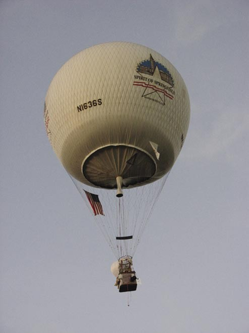
Figure 11-2. “Spirit of Springfield,” a netted gas ballon.
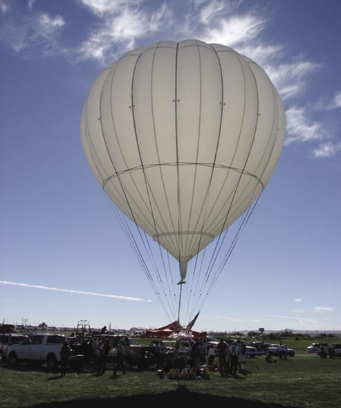
Figure 11-3. Quick fill design gas balloon.
Helium is expensive but is more commonly used in the United States while hydrogen is more common in Europe. Helium provides slightly less lift than hydrogen but is the more stable gas. (See subsection titled Flying in Inversions on page 11-7 for a discussion of stability.) Balloon systems must not be prone to generating static electricity if they are to be used with hydrogen.
There are at least six factors to consider when choosing a lifting gas. These are:
- Compatibility with the balloon system being used
- Cost
- Lifting capacity
- Availability
- Locale of flight
- Inherent gas stability
Normally, the gas selection process starts with the type of balloon. Hydrogen can be used if the balloon system is hydrogen compatible, hydrogen is available, and local ordinances allow its use. If one of these conditions is not satisfied, as is often the case in the United States, then helium is the likely choice. If a very short training or pleasure flight of several hours is planned, the more economical alternative of ammonia or methane (natural gas) may be considered.
When inflating or landing with hydrogen or methane, care must be taken to ensure that no flame or material with the potential to generate sparks is present in the launch locale. Lighted cigarettes, cigars, nylon clothing, cell phones, and other electronic devices are examples of forbidden items. Only essential personnel should be allowed in the launch and landing areas. For long, competitive flights, the increased stability of helium is a factor in its favor.
Components of the Gas Balloon
Gas balloon systems can be broken into four parts:
- Envelope to contain the lifting gas
- Gondola for carrying pilots and equipment
- Support system to connect the envelope to the gondola
- Other equipment
Envelope
The maneuvering valve [Figure 11-4] is at the apex of the envelope. It allows for the controlled release of a small amount of gas to initiate a descent. It is usually spring actuated and controlled via a line that runs from the valve down through the envelope into the gondola. On some balloons, a gas tight parachute top may be used instead of a valve. The envelope is also equipped with either a rip panel or deflation port for rapid, total deflation during high wind landings. More information on proper use of the valve and deflation ports is provided in the section The Practice of Gas Ballooning, page 11-8.
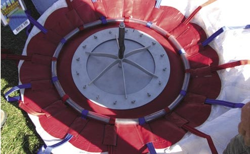
Figure 11-4. Maneuvering valve on quick fill gas ballon.
Gondola
The gas balloon’s gondola [Figure 11-5] is typically somewhat larger than ones used for sport hot air ballooning, with four by five feet being a typical size. A foldable cot or sleeping pad normally runs along the long side of the gondola and a “kick-out” panel in the side wall at one end of the cot may be used to provide additional legroom for sleeping.
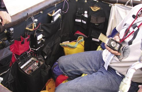
Figure 11-5. Typical gondola layout.
A trail rope is slung on the outside gondola along with much of the remaining support equipment. The trail rope is typically about 150 feet of natural fiber rope, one inch in diameter and weighs about 40 pounds. Its use is described in the landing paragraph.
Support Cabling
The connection between envelope and gondola may be made of rope, flat tape, or steel cable. The total strength of the cabling should have a breaking strength of at least five times the maximum gross load that is suspended on the cables. This must include sand ballast, as well as the weight of the gondola, the occupants, and all supplies and equipment. For hydrogen systems, the cabling must be electrically conductive. For ammonia systems, the cables should be long enough to separate the occupants of the gondola from gas fumes coming out of the appendix.
The bottom end of the cabling is gathered at a load ring which acts as the interface between the envelope and the gondola cables. The load ring also serves as the system’s strong point for attachment of inflation harnesses or trail ropes.
Equipment
Equipment carried varies with the purpose of the flight. A minimum equipment list should include an altimeter/ variometer, compass, global positioning system (GPS), aircraft position lights, several flashlights (for night flights), oxygen (for high altitude flights), aircraft radio, and aircraft sectional maps for navigation and communication. [Figure 11-6] Other items which may be included for safety and occupant comfort may include: a first aid kit, adequate food, water, warm clothing, and toilet facilities for both the planned flight and for the postflight period before the recovery crew arrives.
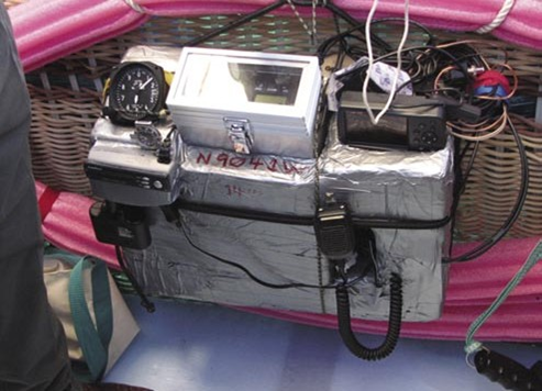
Figure 11-6. Instruments and radios are sometimes carried in a pod such as this.
Theory of Gas Ballooning
Complete books have been written on the theory of gas ballooning and a full discussion of the topic is not possible here. At the very least, three topics must be understood by the competent gas pilot: physics, weather aspects, and the significance of different lifting gases.
Physics of Gas Ballooning
Four main factors are instrumental in determining lift:
- Type of lifting gas used (e.g., helium, hydrogen, or anhydrous ammonia)
- Amount of lifting gas in the envelope (usually equal to the envelope’s total capacity)
- Outside air temperature
- Ambient barometric pressure (which is directly related to altitude and local weather conditions).
Lift at Sea Level
The generation of buoyancy (commonly referred to as “lift”) in a gas balloon is somewhat different from that of a hot air balloon. The basic principle is the same, but for different reasons.
One cubic meter of air weighs 2.702 pounds at sea level under International Standard Atmosphere (ISA) conditions (29.92 inches of mercury (“Hg) and 59 degrees Fahrenheit (°F) at sea level). At the same time, and also under ISA conditions, a cubic meter of helium weighs 0.3729 pounds. The difference between these two numbers, 2.329 pounds, is the gross lift of a gas balloon with a volume of one cubic meter. To determine the gross lift under ISA conditions, it then becomes a simple multiplication of 2.329 pounds times the volume of the envelope. For the standard 1,000 cubic meter gas balloon, the gross lift is 2,329 pounds.
The above calculation is valid for helium. If, however, hydrogen is used as the lifting gas, the factor is 0.189 pounds per cubic meter; anhydrous ammonia’s weight is 1.583 pounds per cubic meter. As compared to helium, hydrogen has 8 percent more gross lift per cubic meter, while ammonia has approximately 50 percent less lift than helium under ISA conditions.
Lift at Altitude
As a balloon ascends, it is generally true that temperature, atmospheric pressure, and gross lift all decrease. Gross lift decreases as pressure decreases, but increases as temperature decreases. Thus, as a gas balloon rises in the atmosphere, the decreasing pressure and temperature oppose each other. The decreasing temperature increases lift while the decreasing pressure decreases lift. Atmospheric pressure changes are more significant than temperature changes. Thus, net lift decreases as altitude increases in a standard atmosphere.
When calculating the effect of changing pressure and temperature, it is necessary to multiply the sea level lift by the ratio of pressures and temperatures. For a nonstandard ambient pressure, multiply the lift at the ISA level either by
29.92 “Hg or 1,013.25 millibars (mb).
Temperatures at altitude must also be calculated and compensated for. The factor for temperature is a ratio of absolute temperatures expressed in either degrees Kelvin or Rankine. To get temperature in degrees Rankine, simply add 459 to the normal Fahrenheit temperature. For a new temperature, multiply the lift calculated at the ISA by the factor: (59 °F+ 459)/(new temperature + 459). When using temperature in degrees Centigrade (°C), add 273 to convert to absolute temperature (i.e., Kelvin). This is: (15 °C + 273)/(new temperature + 273). Various lift factors at differing altitudes, comparing helium and hydrogen, are illustrated in Appendix F.
Pressure Ceiling
The pressure ceiling is the altitude at which the lifting gas inside the envelope would expand to just completely fill the envelope, assuming the balloon rose to that altitude. Rising above the pressure ceiling causes lifting gas to be expelled from the appendix and establishes a new, higher pressure ceiling. Exceeding the current pressure ceiling causes loss of lifting gas, reduces gross lift, and typically causes the balloon to eventually begin to descend. Ballast must be expended to maintain the new higher altitude. However, maneuvers that result in altitude changes below the pressure ceiling, do not result in loss of lifting gas or gross lift. Very little ballast is required to ascend while below the pressure ceiling. For these reasons, the gas pilot should always be aware of what the approximate current pressure ceiling is and should consider the consequences of penetrating that ceiling.
The following approximations generally apply to a balloon below 18,000 mean seal level (MSL).
- For a 1,000 cubic meter balloon at its pressure ceiling, an ambient pressure decrease of 1 “Hg causes a decrease in gross lift of about 80 pounds.
- For a 1,000 cubic meter balloon at its pressure ceiling, an ambient and gas temperature decrease of 3.3 ºF causes a lift increase of about 16 pounds.
- For a 1,000 cubic meter balloon at its pressure ceiling, a discharge of about 64 pounds of ballast results in approximately a 1,000 foot increase in altitude.
Additional Factors That Affect Lift
- A balloon flying below its pressure ceiling (i.e., a flaccid balloon) responds differently from one flying at its pressure ceiling.
- When the lifting gas inside the balloon is warmer (i.e., super heating) than the ambient air, additional lift is generated. The reverse happens when the lifting gas is colder than the ambient air.
- Nonstandard atmospheric conditions, such as inversions, affect a balloon’s stability.
- The atmospheric humidity has a small effect on lift with more humidity resulting in slightly less lift.
- The purity of the lifting gas directly affects lift. Most commercially produced gas is assumed to be greater than 99 percent pure, but purity can be reduced as a result of improper filling technique.
For further discussion of gas balloon calculations, the book A Short Course on the Theory and Operation of the Free Balloon, by C. H. Roth, Goodyear Tire and Rubber Company, is recommended reading. This manual provides a good overview of the physics and operation of gas ballooning as of 1917. It is long out of print, but photocopies are readily available.
Weather Considerations for Gas Ballooning
When studying weather for gas ballooning, one must look for trends both further into the future and higher above the ground. The best weather for any flight is determined by the flight’s objectives. A flight to set a duration record (maximum time aloft) benefits from light winds and clear skies while a distance competition requires high winds aloft with lighter winds in the landing zone. A competitor in a long competition is likely to encounter several different weather patterns during flight simply due to the length of the flight. Examples of these include precipitation, snow, icing, thunderstorms, lightning, high winds, mountain winds, unstable air, or convective currents.
This discussion again focuses on the most common type of competitive flight, a Gordon Bennett type, with the objective to maximize great circle distance covered. Since winning distances can be well over a thousand miles at altitudes of up to 18,000 feet MSL with times aloft possibly exceeding seventy hours, a much larger area of the weather map must be studied than for a typical hot air flight.
Meteorological Differences From Hot Air Ballooning
In contrast to hot air flights, landing conditions are most likely to be different from those at launch and several weather patterns may be encountered during the flight. Freezing levels and the moisture content of the air should be checked to predict the possibility of icing. Any icing that occurs has multiple negative impacts on the flight. It adds weight to the balloon and can interfere with the functioning of the valve by preventing it from either opening properly or from sealing tightly after activation. The weight of the ice should initiate a natural descent to a lower altitude and warmer temperatures. If this does not happen naturally, the pilot may initiate a descent by valving. Be aware that the melting ice at lower altitudes lightens the system and additional valving is necessary to prevent a second ascend back above the freezing level. Falling ice shards have also been blamed for equipment damage on occasional flights. A second strategy against icing is to seek drier air above the saturated air but the higher altitude is unlikely to provide the warmer temperatures needed to melt the accumulated ice.
Encountering thunderstorm activity is much more common in gas versus hot air flights. This is especially dangerous when flying an explosive gas such as hydrogen. Isolated thunderstorms can develop due to solar heating of moist air in the afternoon over the great plains of the United States with very little warning. Prediction and avoidance are the best tools against thunderstorms. Real time contact between the pilots and a ground-based meteorologist with access to forecasting tools to predict the formation of thunderstorms can help to avoid these storms. During the different stages of a thunderstorm, rapid accelerations due to inflows or outflows, as well as rapid ascents or descents, are very likely. The presence of any of these effects, in conjunction with any thunder or lightning are indications that an immediate landing is prudent.
Meteorological Flight Planning
Flight planning for a gas balloon flight starts several days prior to the planned flight. The gas balloon pilot examines numerous meteorological tools, looking at frontal movement to get the big picture, wind speed and direction forecasts at several altitudes, and future times to predict a flight path. Then, they will study forecast precipitation probabilities and freezing levels over the flight period. Modern trajectory predictors, such as the HYSPLIT (www.arl.noaa.gov/ ready.html) program, maintained by National Oceanic and Atmospheric Administration (NOAA) can be a great help. However, the HYSPLIT model gives no forecast for precipitation along the route, so the possibility of rain, snow, or icing must be assessed using other weather models. Often, ideal weather is found just after a frontal passage, after any moisture has cleared but while the air mass is still moving with the departing front. For serious competitions, a professional meteorologist is an invaluable team member and is consulted before and during the flight. A good starting point for weather investigations is NOAA’s aviation weather web site www.aviationweather. gov.
Flying in Inversions
Proper utilization of atmospheric temperature inversions during gas balloon flights can result in increased flight stability and ballast conservation. Figure 11-7 shows a simplified atmospheric temperature lapse chart when no inversion is present. Figure 11-8 is similar but with an inversion present. In both charts, altitude increases up the vertical scale and temperature increases going to the right on the horizontal scale. Figure 11-7 shows temperature decreasing consistently with altitude, while Figure 11-8 has an inversion zone (inside red circle) from 2,000 to 4,000 feet.
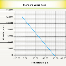
Figure 11-7. Standard temperature lapse chart.
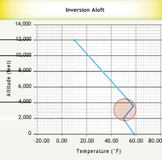
Figure 11-8. Atmosphere exhibiting an inversion.
in which the temperature increases with increasing altitude. A gas balloon flying in this inversion has the advantage of increased stability as compared to the altitudes above or below the inversion which exhibit normal lapse rates.
To explain this, it is important to understand the term “stability” with respect to a gas balloon. Stability can be imagined as an invisible hand that gently pulls the balloon down whenever it starts to rise or alternately pushes the balloon back up as it starts to fall. A balloon flying in stable weather tends to fly level with very little intervention from the pilot. However, stability is a weak condition and can be overcome by many factors, such as gain or loss of solar heating, orographic winds, and ballasting or valving.
To understand why an inversion creates stable flying conditions, think of a gas balloon flying at 3,000 feet in the middle of the inversion. If, for some reason, the balloon starts to ascend, two things happen. First, the balloon enters warmer ambient air. Second, the lifting gas inside the balloon expands and cools adiabatically as it reaches the slightly lower pressure atmosphere of the higher altitude. Both of these effects cause the balloon to lose lift and to descend. It is helpful to remember that, as a hot air balloon either cools or enters hotter air, the temperature differential between outside and inside air decreases and lift is lost. The same principle applies here, as applied to gas balloons. Subsequently, if the gas balloon descends from its starting point, it encounters cooler outside ambient air and its interior gas compresses and warms adiabatically, therefore gaining and ascending back to its original altitude. Remember, in an inversion, either motion (ascending or descending) tends to cause an opposing force to passively initiate a return to the original altitude.
With proper planning, the gas balloon pilot can take advantage of this scenario. Weather theory teaches that inversions often set up at night either right at the surface (sometimes referred to as “surface inversion”) or at some altitude above the ground (generally referred to as an “inversion aloft”) as shown in Figure 11-8. Visible signs of an inversion may be pollution trapped below the inversion causing reduced visibility and dirty looking air. Invisible signs of an inversion may be significantly more stable flying conditions in the inversion area. If a slow, steady initial ascent is initiated (best done by launching with a flaccid balloon), the balloon may find an inversion with no help from the pilot by leveling off as it enters the inversion zone. More likely the pilot has to hunt for the inversion; inversion levels can be determined from the use of the Skew-T charts as previously discussed in Chapter 4, Weather Theory and Reports.
As an example, during flight at night very near the ground, a pilot may feel he or she is continually ballasting to fly level. If a pilot suspects an inversion aloft may exist above, he or she can initiate a slow ascent. If the envelope is flaccid and the ambient air at this altitude is not inverted, then the balloon tends to continue rising until it either encounters an inversion or becomes full as it reaches its pressure ceiling. If the balloon levels out while it is still flaccid, this may indicate that it has entered an inversion zone. If the balloon continues to fly level passively, it is flying in an inversion.
The Practice of Gas Ballooning
Gas Balloon Regulations
For a pilot with a hot air rating, certification to fly gas balloons requires the removal of the “with airborne heater” limitation on his or her certificate. For a private pilot gas rating, aeronautical experience requirements in Title 14 of the Code of Federal Regulations (14 CFR) section 61.109(h)
- require “…at least two flights of at least 2 hours each that consists of
- At least one training flight with an authorized instructor within 60 days prior to application for the rating on the areas of operation for a gas balloon;
- At least one flight performing the duties of pilot in command in a gas balloon with an authorized instructor; and
- At least one flight involving a controlled ascent to 3,000 feet above the launch site. ”
The regulation for removal of the airborne heater restriction from an existing hot air pilot’s certificate (14 CFR Section
61.115 Balloon ratings: Limitations) states:
- The limitation may be removed when the person obtains the required aeronautical experience in a gas balloon and receives a logbook endorsement from an authorized instructor who attests to the person’s accomplishment of the required aeronautical experience and ability to satisfactorily operate a gas balloon.
NOTE: Only a logbook entry is required to complete the process (no check ride), since the gas authorization is a removal of a restriction from an existing rating rather than an issuance of a new rating.
The regulations for the aeronautical experience for a commercial rating are virtually identical according to 14 CFR section 61.129(h)(4)(i) except that the student must act as pilot in command on both flights and the controlled ascent must be to “…5,000 feet above the launch site.”
Additional areas of specific interest to gas balloon pilots are the regulation for currency for night flight according to 14 CFR section 61.57(b)(1):
“…no person may act as pilot in command of an aircraft carrying passengers during the period beginning 1 hour after sunset and ending 1 hour before sunrise unless within the preceding 90 days that person has made at least three takeoffs and three landings to a full stop during the period beginning 1 hour after sunset and ending 1 hour before sunrise.”
NOTE: This is similar to the currency for day flight and only applies to flights with passengers. It does not prohibit night flight when only pilots are on board.
Also of interest are the sections on aircraft lights (14 CFR section 91.209) for night flight; the use of supplemental oxygen (14 CFR section 91.211), and the use of transponders (14 CFR section 91.215).
Flight Planning
During the planning stage of the flight, the objectives of the flight should be established. Possibilities include: training, pleasure, competition, record setting, new equipment checkout, or possibly scientific investigation. Then, the expected flight parameters should be developed. These include the number of pilots and passengers, balloon parameters (type, size, and lifting gas to be used), launch time and location, expected duration, required weather, maximum altitude, and predicted landing zone. If a fixed date has been selected for the flight, an initial meteorological assessment should be made approximately three days out and subsequent weather developments are used to make a “go/no-go” decision. If the flight date is flexible over an extended time window, continual monitoring of the weather is required until proper conditions develop.
After this, an equipment list can be developed and a system weight and ballast calculation should be performed. Permission to use the desired launch site must be confirmed and the availability of adequate gas supply and launch and chase crew must be assured. A concise schedule should be sent to all crew members, defining when decisions are made and how these decisions are communicated to the crew.
Finally, all inflation and flight equipment must be assembled and checked out for proper functioning. The chase vehicle selected should be able cover the expected distance and bring all participants back home.
Layout and Inflation
When the day comes, all equipment is transported to the launch site. A site “walk-around” is performed to remove debris and trash and to check for obstructions to inflation or takeoff. Layout and assembly differ by balloon type, but should proceed according to the balloon’s flight manual. For quick fill balloons, layout should be downwind, similar to hot air balloons. A crew briefing should be performed and a crew chief should be designated. Safety must be emphasized; new crew members must be given specific instructions and be assigned to a more experienced crew member for guidance. Gas balloon launches still tend to draw a crowd and some form of crowd control may be required. [Figure 11-9].
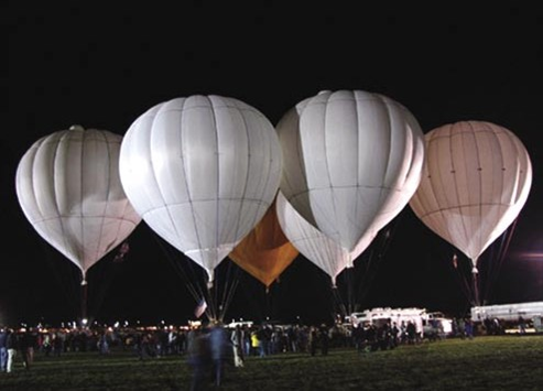
Figure 11-9. America’s Challenge launch at Fiesta Park, Albuquerque, New Mexico.
A launch restraint should be secured and additional inflation ballast (weighing several hundred pounds more than the pilots and supplies that eventually are on board) should be added to the gondola.
The start of gas flow is a critical point in the inflation. A slow initial flow allows a last minute check of cable routings and crew positions. Surface weather conditions determine flow rate after the initial checkout. For quick fill systems, a partially filled envelope is much more subject to twisting in wind gusts. A flaccid envelope tends to present a concave (spoon-shaped) surface to the wind, producing a higher drag factor and placing more stress on the entire system. Once the envelope’s shape has filled out to a convex (beach ball) shape, it is more able to stand by shedding wind gusts around it. Quick fill systems are much more subject to this effect than are netted balloons.
As described in the section on balloon systems, a netted balloon envelope is laid out flat on the ground and its shape during inflation resembles a sphere rising out of the ground. It always presents a convex (shedding) shape to the wind. A separate step is required after inflation to install the basket and attach it to the load lines coming down from the net.
A good rule of thumb is to take no more time than is necessary to complete the fill. This is especially true in windy conditions.
Launch
With the use of a checklist, confirm that all required equipment items and pilots are on board. A launch master is usually assigned to direct removal of excess inflation ballast until the system is neutrally buoyant. Desired ascent rate determines how much additional ballast is removed to attain the proper amount of positive buoyancy. The launch master should be an experienced gas balloonist and direct crew to allow the balloon to rise several feet off the ground several times to test the buoyancy before instructing the crew to bring it back to the ground one last time before final release. If the ascent rate is too slow, additional ballast are removed until the proper rate is achieved. After a final check for airspace clearance above, the “Hands off!” command is given and the balloon is allowed to fly free. [Figure 11-10]
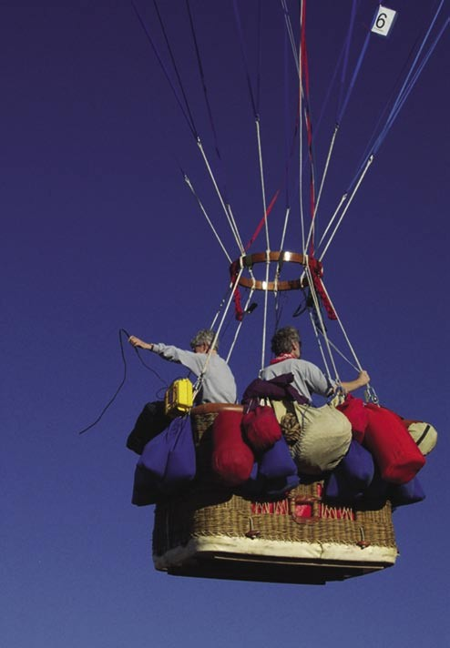
Figure 11-10. A gas balloon, shortly after the weigh off procedure, ascends into the sky.
Inflight Procedures
All other things being equal, a gas balloon’s natural tendency is to find its equilibrium altitude and to fly level at that altitude. By contrast, a hot air balloon’s natural tendency to descend must be counteracted with periodic infusions of heat. In a gas balloon, pilot action is only required to initiate or arrest an ascent or descent or to counter atmospheric or other disturbances. A gas balloon may fly for an hour or longer with no intervention by the pilot. Pilot initiated altitude changes with gas balloons tend to occur at a slower rate over a longer time period as compared to hot air ballooning.
Ascents are initiated by jettisoning ballast (usually sand or water) while descents result from releasing lifting gas from a valve at the top of the envelope.
Significant midflight altitude changes are often undertaken as part of a long-term strategic plan rather than for short term tactical reasons. The consequences of any maneuver should be considered carefully before being undertaken. It is often stated that ballast is the fuel of a gas balloon and well before all ballast has been expended, the aircraft must be safely back on the ground. Use of large amounts of ballast to execute a major ascent invariably shortens the potential duration of a flight.
For example, in a distance competition, an ascent from the surface to 12,000 feet MSL may be executed to enter more favorable winds. This may take 1 hour to accomplish but that altitude may then be maintained for the next 8 hours if weather conditions are stable.
Two additional concepts that must be understood to pilot gas balloons are solar heating and lifting gas purity.
Solar Heating
Solar heating (also called super-heating) occurs when the heat of the sun is trapped inside the balloon’s envelope and causes the temperature of the lifting gas to exceed the outside air temperature. As the heated lifting gas expands, one of two things will happen. If the envelope is flaccid, the less dense gas occupies a larger fraction of the envelope’s volume and displaces more air and the system’s gross lift temporarily increases. This causes the balloon to rise towards its pressure ceiling and it also temporarily causes the pressure ceiling to drop. When the envelope becomes full (i.e., reaches its pressure ceiling), gas is expelled and a new ceiling is established.
If the flight is continued through sunset, loss of solar heating results in a cooling of the lifting gas and a resultant loss of gross lift. Ballast must then be used to maintain buoyancy.
Purity of Lifting Gas
A final topic of interest is the effect of mixing air with the lifting gas. It may seem that since air is heavier than the lifting gas, the air would have a tendency to pool at the bottom of the envelope and be expelled through the appendix as the balloon rises into less dense air. However, this is not what happens. The forces of molecular attractions cause the air and lifting gas to become permanently mixed and a generally less pure mixture occurs. When this happens, some of the benefits of operating under the pressure ceiling are lost and every up/down maneuver causes the loss of lifting gas along with the expelled air.
For this reason, care should be taken to close the appendix when descending rapidly to avoid allowing air to force its way up into the envelope through the open appendix. Maintaining a high level of purity of the gas inside the envelope can extend flight duration. Care must be taken to open the appendix during rapid or prolonged ascents which bring the balloon close to its pressure ceiling. Ascent above pressure ceiling with a closed appendix increases internal pressure on the envelope’s fabric and, in an extreme case, could cause the envelope to rupture.
Landing, Retrieval and Packup
The landing phase is the single most critical portion of the entire flight. The pilots may be fatigued from the long flight. They may be in unfamiliar geography and weather conditions. There may be time pressure to land in daylight if sunset is approaching. A landing after dark, under a full moon and in open territory may be performed rather routinely, but a daylight landing is still much preferred. A night time landing in dense woods under a new moon or with reduced visibility can be very stressful. Five minutes on oxygen prior to landing may help to relieve some fatigue and clear the senses.
The landing decision varies with each flight and should be discussed jointly among all the pilots. Landings should be initiated while there is still adequate ballast available to abort at least one approach, if necessary. The actual amount of ballast required varies with pilot experience, weather conditions, terrain and descent rate. For a 1,000 cubic meter balloon in relatively easy landing conditions and under a shallow descent, 50 pounds may suffice. Under more adverse conditions, 250 pounds or more may be advisable. Additional considerations for landing may include duration of flight, fatigue level of the pilots, accomplishment of the flight objectives, current and forecast weather, terrain, and time of day.
When the decision is made to land, all possible equipment should be securely stowed. Occupants should don helmets and any other protective gear. All antennas, solar panels, and other items hanging below the basket should be retrieved and stowed. Adequate ballast should be brought inside the basket where it is readily available to abort or round-out a landing.
The trail rope should be rigged and readied for deployment. The trail rope serves three purposes. First, it slows the descent rate. A fully deployed trail rope weighing about 40 pounds on a 1,000 cubic meter balloon normally arrests a descent of approximately 340 feet per minute (fpm) at 150 feet above ground level (AGL) to a descent rate of 0 fpm at ground contact. The descent from 150 feet will take about 45 seconds. These numbers are only approximations and local conditions at landing certainly cause these to vary somewhat. Secondly, the trail rope orients the balloon so the attachment point of the rope is on the upwind (or trailing) side of the basket. This may be important depending on the arrangement of the basket and/or deflation ports. Finally, as more of the rope contacts the ground, friction slows the horizontal speed of the balloon. The trail rope should be connected to the load ring with a quick release mechanism to allow release should the trail rope become permanently entangled on the ground.
If the gondola has rotated during flight, placing the trail rope on the gondola’s downwind side, it does not deploy correctly unless the pilot guides it around to the upwind side of the gondola. Otherwise the rope deploys under the gondola and tends to pull the leading edge of the gondola down and may completely invert it. This is colloquially called “dog-housing” and puts the occupants in the uncomfortable position of being dragged along the ground trapped inside the basket. Unlike modern hot air balloons, most gas balloon systems do not have rigid uprights, so dog-housing is a real concern in a high wind landing; the best antidote is to keep as much weight as possible (including the occupants) on the upwind (trailing) side of the basket.
The trail rope also acts to stop any ascent since a rising balloon becomes heavier as more of the rope is lifted off the ground. This is why it is sometimes called “retrievable” or “reusable” ballast. For this reason, the trail rope should never be deployed until landing is completely certain. Aborting a landing with a deployed trail rope requires ballasting the weight of the trail rope (approximately forty pounds) in addition to the ballast normally required to achieve the desired ascent rate.
The anti-sail line should be pulled tight and secured to the load ring or other strong point. The purpose of this line is to hold the bottom of the envelope down taut to minimize drag in a high wind landing. If the envelope is allowed to ride free, it rides up and bows in the wind, forming a scoop that catches much more wind and increases the length of the drag along the ground.
At this point, the descent is initiated and one or more potential landing sites should be identified. If the descent continues as expected and an adequate landing site is attainable, the descent rate should be tailored toward that site. A last check should be made for powerlines and other obstructions on the path to the landing site. The area downwind of the site should also be checked in case landing runs long. Only then, at a height above ground equal to the length of the trail rope (usually about 150 feet), and only if there are no intervening obstacles between the balloon and the landing site, will the trail rope be deployed. [Figure 11-11]
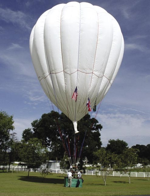
Figure 11-11. A successful gas balloon landing.
As with a hot air balloon, if a fast layer has been encountered during the descent, it may be advisable to level off at an altitude below the fast layer to burn off some momentum. However, if this jeopardizes hitting the only likely landing site, a high wind landing is the better option.
The final phase of the landing is ground contact, and just as in piloting a hot air balloon, a decision must be made to perform either a rip-out or standup landing. Contrary to hot air ballooning, in gas, rip-out landings are the norm. Up to the final moment, ascent rate is controlled by actuating the valve (or parachute) to release small amounts of lifting gas. As in hot air ballooning, both pilots should be positioned for landing. Typically at about five feet AGL, the deflation port line (usually red) is pulled to open the port and release a large quantity of gas immediately. Some systems may have multiple deflation ports. Once the deflation port is activated, the flight is terminated with a rapid descent, so it is important to be close to the ground before activation. The height of activation can occasionally be as high as thirty to fifty feet in for emergency reasons, but a very hard landing is sure to ensue.
On the newer German (Wörner) balloons with sealing parachute tops, it is possible to reseat the parachute after a deep activation of several seconds, but gas equivalent to many bags of ballast has been lost. Shorter, shallower vents are used on these systems for maneuvering, but deflation is achieved with a deep constant pull on the parachute line.
Once the balloon has come to a stop and is no longer buoyant, the pilots exit and attempt to contact the chase. Any medical concerns should be dealt with immediately. Landowners should be located, if possible, and an inventory of the contents of the gondola should be done to check to see if anything bounced out during the landing. If darkness is near and no houses are in sight, flashlights, a compass, and GPS should be located immediately to ensure that bearings are not lost in the dark. On a long flight, it may be several hours until the chase crew arrives, but when they do, pack-up proceeds in reverse of assembly.
The America’s Challenge Race, 2006
The 2006 America’s Challenge gas balloon competition is considered by many in the gas balloon community to be one of the most exciting and controversial flights in recent years. It is presented here as an illustration of the skills and decision-making processes necessary for a successful gas balloon flight.
In July 2006, two gas balloon pilots from Georgia, Andy Cayton and Danni Suskin, were to participate in the Gordon Bennett challenge competition in Belgium. Upon preparation for launch, it was discovered that the balloon to be used had some mechanical problems that kept the Cayton-Suskin team from flying. Cayton came back to the United States with every intention of winning the America’s Challenge in the hope of having the opportunity to pursue a victory in the following year’s Gordon Bennett. As Suskin was unable to participate in the event, Cayton selected Kevin Knapp of North Carolina as his co-pilot for the America’s Challenge.
Launch was originally scheduled for the evening of October 7, 2006. Don Day, a meteorologist who worked with Cayton on numerous world record hot air flights as well as other gas flights, was located at the launch field in Albuquerque, New Mexico. In conference with Cayton and Knapp, Day determined that the weather would be a significant factor in the launch and in any subsequent flight track across the United States. The initial track for the planned launch date would have put the team on a northeasterly track towards Canada; but, low freezing levels and thunderstorms east of the Sandia Mountains forced race officials to delay the planned launch. The next launch window, Tuesday, October 10, showed a potential track east, paralleling Interstate 40.
During the 3-day weather delay, Cayton had reason to reevaluate some strategic issues regarding the flight. One concern was the fact that both he and Knapp were fairly large men; he felt that this might place them at some disadvantage over teams with smaller pilots. Smaller pilots are able to carry more ballast, and thus can extend their flight time. Also, while disappointed with the no-fly situation at the Gordon Bennett, he realized that this might provide an advantage, as he would not be attempting a second duration flight while still fatigued from the Gordon Bennett. Cayton believed that these two issues balanced out, and continued with Knapp to prepare for the launch.
Tuesday, October 10, arrived clear and cold; the cold front and low-pressure system that had delayed the initial launch had passed through the Albuquerque area and was now ahead of them. A massive cold front would push through Canada into the central United States and move to the Gulf of Mexico during the second day of flight. The plan was to stay between the two systems to remain competitive and safe. With crew chief Ken Draughn and help from competitors Peter Cuneo and Bert Padelt, the inflation went smoothly. [Figure 11-12]
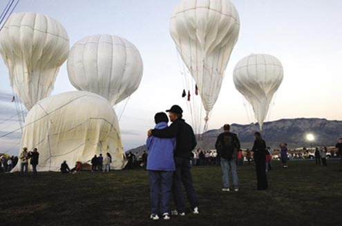
Figure 11-12. Inflation of the America’s Challenge balloons, Albuquerque, NM, October 2006.
As launch position had been previously drawn by lot, the Cayton-Knapp team was the fifth balloon to launch. Early on the evening of the 10th, Cayton handed two bags of ballast to the balloonmeister, Stefan Handl, and they were in the air. The race was on! Knapp remembers many “good luck” calls from the crowd; the chase crew mounted their vehicle and departed the launch field not knowing they would have a role in one of the most controversial events in years
Cayton-Knapp tracked more easterly than the balloons that had previously launched and stayed well north of highway I-40 as they crossed the Sandia Mountains. Their altitude was well above 10,000 feet the first night and averaged 30 miles per hour (mph) with the temperature in the low 30’s. Cayton and Knapp spent most of the night colder than expected and shivering to keep warm. They established radio contact with Lubbock, Texas Approach at 0630 Wednesday morning and shortly after experienced the magic of a sunrise from the air. Most of Wednesday was spent flying over Texas, averaging 36 mph. Another team, that of Phil McNutt and Brian Critelli, flew 90 degrees directly below them passing to the north just before they reached the Dallas/Fort Worth metroplex. [Figure 11-13] Cayton-Knapp could see other balloons in the distance, but it was unusual to see another team’s balloon so close in flight. Dallas Approach directed them to fly over the Class B airspace above 11,000 feet; at that altitude, they started tracking a more southerly direction.
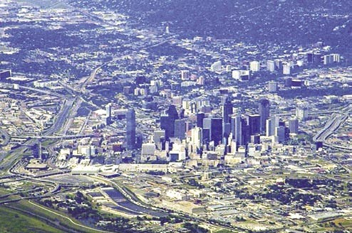
Figure 11-13. Dallas, Texas, from 11,000 feet, as seen from the Cayton-Knapp balloon in flight.
Wednesday evening found the team over northern Louisiana. Most of the night was spent above 2,500 feet flying less than 12 mph. The strategy was to stay behind the weather system ahead and to position themselves for Thursday’s flight. Cayton and Knapp fell behind several teams during the night, but that served to let them know they were where they needed to be.
Thursday morning’s weather forecast was not favorable; winds on the surface, as well as at 3,000, 6,000, and 9,000 feet were all going out into the Gulf with no options but to land. Several teams saw this and landed. Meteorologist Day and Cayton had a long discussion via satellite phone, and confirmed the winds above 12,000 would hook out into the Gulf and bring them back to dry land near Panama City, Florida. All the available meteorological information told them it would work. If the team wished to stay competitive, they had to go high and out over the water.
They began their ascent around 10:00 AM and went out over the water just east of New Orleans. It was relatively slow going but Cayton and Knapp finally made it back to land as planned and began a slow descent around 16:30. Equipment was secured in anticipation of a possible landing near the Apalachicola National Forest in the Florida panhandle. After confirming their position in the race, and with no place to land, the decision was made to continue the flight through the night. The weather prognosis was good, the winds would be relatively calm during the night and remaining ballast was good, so they calculated the needed distance and time to win the race. [Figure 11-14]
Early on Thursday morning, it appeared that the team’s patience had paid off. By 0430, they were moving east about 6 mph and were just over Cross City, Florida. At sunrise, they were 13 miles further east, and just north of Old Town and Fanning Springs. Surface winds were calm and there was a thin layer of ground fog. As the sun came up, the balloon experienced solar heating and ascended to just over 7,000 feet. The flight continued in an easterly direction at 15 mph and by 08:00 the team came to the realization that they were in a perfect position to take over the lead.

Figure 11-14. Panama City Beach, Florida, as seen from the Cayton-Knapp balloon, 25 miles out over the Gulf of Mexico.
As the Cayton-Knapp team crossed Interstate 75, just south of Gainesville, Florida, they received word that the German team of Eimers/Winker [Figure 11-15, AC-13] was on the ground, and near Cayton’s home in Savannah, Georgia. Cayton and Knapp elected to continue flying until they had a cushion of 10 miles before beginning their descent.
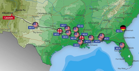
Figure 11-15. Tracks of the 2006 America‘s Challenge competitors.
With surface winds of approximately 3 mph and knowing the race was won, the team elected to land in Citra, Florida. Their chase crew was waiting for them in the yard of a cooperative landowner. After a 60 hour, 20 minute flight covering 1,478 miles, Andy Cayton and Kevin Knapp had beaten the odds to capture the 2006 America’s Challenge Cup.
Chapter Summary
This chapter provides a short description of the unique aspects of gas ballooning in comparison to hot air ballooning. For more information, a local gas pilot and the Gas Division of the Balloon Federation of America (www.bfa.net) are good resources.


