Although powered parachutes come in an array of shapes and sizes, the basic design features are fundamentally the same. All powered parachutes consist of an airframe (referred to as a cart) a propeller powered by an engine, and a ram-air inflated wing. [Figure 3-1]
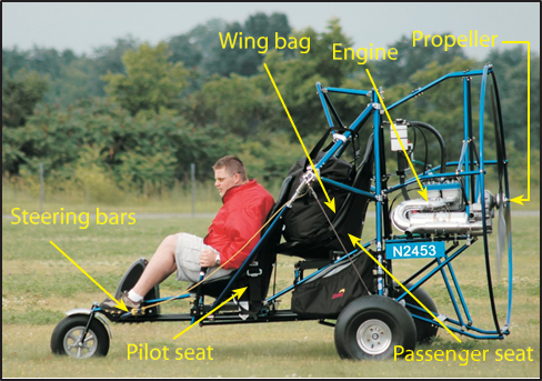
Figure 3-1. A typical powered parachute cart.
The Airframe
Most powered parachute airframes are manufactured with aircraft-grade hardware. A few PPC manufacturers are building fiber-composite carts. The airframe’s tubular construction means light weight and ease of replacement if tubes are bent. The airframe includes one or two seats, flight controls, and an instrument panel. The airframe also incorporates the engine, the fuel tank, the propeller and points of attachment for the wing and steering lines.
Although side-by-side configurations exist, in most powered parachutes the pilot and passenger are seated in a tandem (fore and aft) configuration. Dual flight controls are required for training. Not all PPCs have full dual controls; depending on the configuration of the cart and added controls (that are optional from different airframe manufacturers) the flight instructor can adequately control the aircraft during training from the rear seat during takeoff, flight, and landing procedures with dual throttle controls. While in the rear seat, the flight instructor can have positive control of the aircraft at all times by physically pulling on the steering lines and using a dual-control throttle. Like airplanes, not all powered parachutes are adequately configured to conduct flight training. The flight instructor with a powered parachute endorse- ment should determine his or her ability to control each individual PPC from the back seat with the dual controls for training purposes. [Figure 3-2]
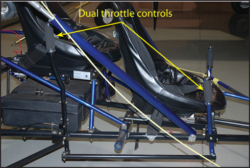
Figure 3-2. Powered parachutes used for training must be equipped with dual controls.
The pilot flies from the front seat in order to reach the steering bars, throttle control, ground steering control, and magneto switches, and to keep the CG in balance; you cannot fly alone from the back seat for this reason.
The cart by itself is not very aerodynamic because it does not need to be; it flies at slower airspeeds. However, without the wing attached and inflated to limit speed, the pilot needs to be careful to avoid high speeds, such as when taxiing to and from the hangar for canopy layout. The wheels, their bearings, and the cart suspension were not designed to handle high speeds. Some manufacturers use an adjustable front seat to allow for the varied length of the pilot’s legs to comfortably reach the steering bars.
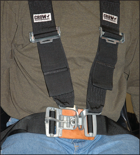
Figure 3-3. The harness should be fastened snug but not tight.
Powered parachutes can be outfitted with a variety of seat- belts, including a four-point harness system that securely fastens each occupant into their seat. [Figure 3-3]
Most powered parachutes have three wheels, or a tri-cycle gear configuration, although some have four. Ground steering is typically a steering bar connected to the nosewheel that moves left and right. Some powered parachutes have a tiller device for ground steering. There are a number of ground steering designs that vary between manufacturer, make, and model.
Brakes are an optional piece of equipment on the powered parachute, as the square foot area of the parachute itself provides aerodynamic braking. Pilots should use smooth and controlled operation of the throttle on the ground to maintain safe and controllable ground speeds, particularly when taxiing with the chute inflated. Students should practice throttle control to learn how far the PPC takes to come to a full stop when the power is reduced to idle. However, for runway incursion prevention and general safety, brakes are advised and highly recommended so you can stop when you need to. Never use your feet as a form of braking, as physical injury is probable.
Center of Gravity Adjustments
Each manufacturer has specific procedures in the Pilot’s Operating Handbook (POH) to adjust the CG of the cart, so that the cart is hanging at the proper nose high/nose low position— including the weight position in the cart and the fore/aft position of the wing attachment points.
As discussed in Chapter 2, the attachment points for the wing (parachute) must be adjusted for variations in pilot weight, which affect the center of gravity (CG) location of the cart.
There are typically two types of wing attachment systems: center of gravity adjustment tubes, or a bracket with a number of fore and aft attachment points. Each of these systems performs the same task. Either system adjusts the wing attachment points based on the cart CG. This is primarily based on the weight of the occupant in the front seat, usually the pilot. The rear seat occupant’s weight does not typically come into consideration when determining the CG position of the PPC, as the rear seat is usually positioned very near the cart CG. To maintain the best overall performance, the aircraft needs to fly with a slight nose-up attitude, as specified in the aircraft POH.
Use the POH to determine the proper adjustment for the particular aircraft because there are many configurations and designs that vary by manufacturer, make, and model.
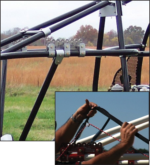
Figure 3-4. Multiple attachment points for the wing as a means to adjust the wing hang point.
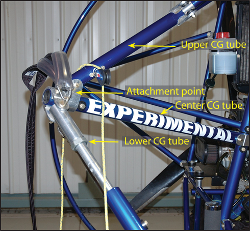
Figure 3-5. PPC CG adjustment example.
Multiple Attachment Points Bracket
The attachment point bracket on the cart is one method to select the fore and aft wing attachment position for proper CG adjustments. [Figure 3-4] Always refer to the POH for weight and balance information specific to the powered parachute you are flying.
Center of Gravity Adjuster Tubes
The term “CG tubes” sometimes refers to the three tubes that meet at the point of rigging for the wing (upper CG tube, lower CG tube and center CG tube). [Figure 3-5] Sometimes the term “CG tube” refers only to the tube that is adjustable, and the other tubes that meet at the rigging points are called outrigger arms.
Instrument Panel
The instrument panel is in front of the pilot and provides engine and flight information. The pilot is responsible for maintaining collision avoidance with a proper and continuous scan surrounding the powered parachute, as well as monitoring the information available from the instrument panel. The pilot must process the outside cues along with the instrumentation throughout the flight for a sound decision-making process.
The ignition switches are usually located on the instrument panel and have two positions: ON, which allows power to make contact with the spark plugs,
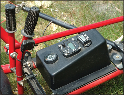
Figure 3-6. Some instrument panels will have just a few digital or analog gauges for EGT and RPM.
or OFF, which is a closed switch to GROUND and removes the power source from the spark plugs. Typically, PPC engines have two spark plugs per cylinder, two switches, and two completely separate ignition systems. Some single-place PPCs with smaller engines have only a single spark plug per cylinder, one ignition switch, and a single ignition system.
The FAA defines the required minimum instrumentation for PPCs; engine manufacturers may recommend certain instruments be installed on the aircraft to monitor the performance of their particular engine. For example, on a liquid-cooled engine, the manufacturer may recommend instrumentation to monitor engine gas temperatures (EGT), water temperatures, and RPM. On an air-cooled engine, the manufacturer’s recommendation may be EGT, cylinder head temperature (CHT), and RPM. Additional instruments can be added as desired by the individual aircraft owner.
Some PPCs may only have a few analog gauges. [Figure 3-6] Some makes and models may be equipped with an engine information system (EIS). [Figure 3-7] The EIS is a flight computer and screen that receives input signals from sending units connect- ed to engine and flight probes or sensors. The computers are pre-programmed for different makes and models of engines. Engine information may include RPM, EGT, CHT, water temperature, fuel quantity, an hour meter and a voltmeter. Flight instruments may include an altimeter, vertical speed indicator and a GPS.
This engine and flight information is viewed on the LCD screen and has function keys, allowing the pilot to move between display screens that contain the computer’s input. When the display button is pressed, each individual screen will clearly identify the information being displayed.
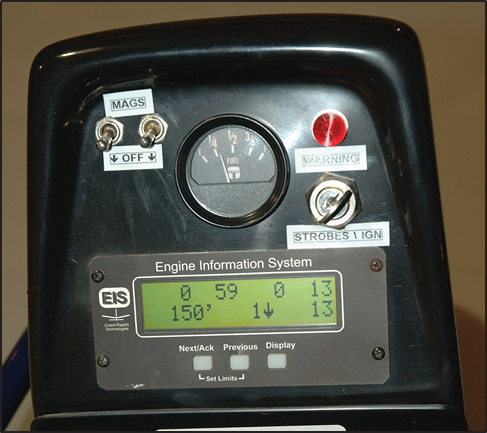
Figure 3-7. Typical engine information system.
The information systems are also capable of alerting the pilot when any engine or flight parameters are exceeded, usually via a warning light mounted on the instrument panel. Although the EIS is a valuable tool, the ability to interpret the information is equally important.
For the interpretation of any engine and flight instrument, you need to completely understand the engine limitations, parameters, and the messages the instrument provides you. Sensing the proper operation of the aircraft and engine is a key factor to the safe operation of any aircraft. Being able to interpret engine sounds and unusual vibrations is essential for any pilot.
As with any aircraft or instrument operation, see the POH for each individual make and model operating instructions.
Additional Equipment
A GPS can sometimes be used to determine ground speed while flying. A GPS is also a useful tool to enhance navigation for cross-country flying. Review Chapter 14 of the Pilot’s Handbook of Aeronautical Knowledge for information on the calculations associated with determining wind speed, ground speed, fuel consumption, and time en route. Communication and navigation radios, transponders, GPS, and LORAN receivers are not required to fly a powered parachute in Class G airspace. You must have the required equipment on board to operate in Class B, C, D or E airspace.
Equipment requirements can be found in the regulations. Powered parachutes must meet these requirements. Even though many powered parachutes have strobe lighting to aid in the visual sighting of the aircraft, additional positional lighting is required for night operations. See Chapter 12 for more information.
Electrical System
Powered parachutes are typically equipped with a 12-volt direct-current electrical system. A basic powered parachute electrical system consists of a magneto, alternator or generator, battery, master/battery switch, voltage regulator, and associated electrical wiring.
Electrical energy stored in a battery provides a source of electrical power for starting the engine and a limited supply of electrical power for use in the event the alternator or generator fails.
The electrical system is turned on or off with a master switch. Turning the master switch to the ON position provides electrical energy to all the electrical equipment circuits with the exception of the ignition system. Equipment that commonly uses the electrical system for its source of energy includes:
- Position lights.
- Anticollision lights.
- Instrument lights.
- Radio equipment.
- Electronic instrumentation.
- Electric fuel pump.
- Starting motor.
Fuses or circuit breakers are used in the electrical system to protect the circuits and equipment from electrical overload. Spare fuses of the proper amperage limit should be carried in the powered parachute to replace defective or blown fuses. Circuit breakers have the same function as a fuse but can be manually reset, rather than replaced if an overload condition occurs in the electrical system. Placards at the fuse or circuit breaker panel identify the circuit by name and show the amperage limit. An ammeter is used to monitor the performance of the electrical system. The ammeter shows if the alternator/generator is producing an adequate supply of electrical power. It also indicates whether or not the battery is receiving an electrical charge.
A voltage meter also provides electrical information as to the battery voltage, an additional status of your electrical system.
A voltage regulator changes the variable output of the magneto or generator to the 12-volt DC level for the battery and the electric system. The voltage output is typically higher than the battery voltage. For example, a 12-volt battery would be fed from the magneto/gen- erator/alternator system through the voltage regulator which produces approximately 13 to 14 volts. This higher voltage keeps the battery charged.
The Steering Bars
The steering bars are located just aft of the nosewheel and mounted on each side of the aircraft; they move forward and aft when the pilot applies foot pressure. [Figure 3-8] The steering lines from the trailing edge of the wing are attached to the outer ends of the steering bars. (Some manufacturers have developed a steering pedal system on their airframes, although the steering lines function in the same manner.) The main steering lines divide into various smaller lines, which attach to multiple points on the trailing edge of the wing. Pushing on either one of the steering bars causes the steering lines to pull down the corresponding surface of the trailing edge on the wing, creating drag. This in turn slows that side of the wing and banks the PPC into a turn.
Pushing both steering bars simultaneously causes the steering lines to pull down equally on the trailing edge, which causes two things to happen: it decreases the powered parachute’s forward speed by increasing the drag and it changes the shape of the wing,
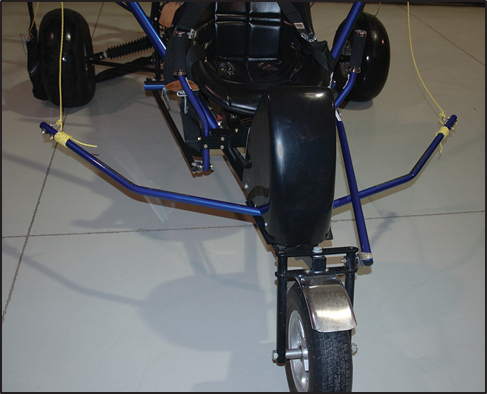
Figure 3-8. Steering bars are located just aft of the nosewheel and mounted on each side of the aircraft.
increasing angle of attack which increases lift. This procedure, called “flaring” or “braking the wing” allows the pilot to touch down at a slower rate of speed and descent, thus creating a smoother landing, which results in less wear and tear on the aircraft as a whole. [Figure 3-9]
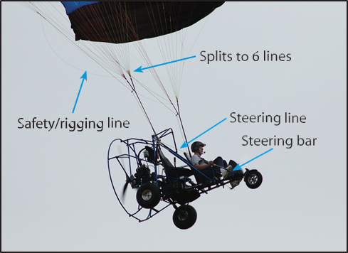
Figure 3-9. Steering lines are divided into two sections; a single heavy line is attached to the steering bars.
Wings and Components
The powered parachute wing is unique, as compared to a fabric wing on an airplane, in that when it is not inflated it loses its ability to produce lift. When a powered parachute wing is inflated or pressurized, it becomes semi-rigid and is capable of producing lift and supporting a load. Rather than being bolted to the fuselage like an airplane, the parachute wing is attached to the cart by lines and cables which are known as risers.
The wings are manufactured by attaching an upper and lower section of skin to ribs. [Figure 3-10] The ribs of the wing determine the airfoil shape. [Fig- ure 3-11] The shape of a powered parachute wing will change slightly when faced with different gross weights, air pressures, and environmental conditions such as moisture, air temperature and wind.
Different wing manufacturers use different fabric treatments to render the fabric airtight, so the air that enters the wing cannot escape through the fabric sur- face. The top surface of the wing is generally treated to help protect it from ultraviolet light and the elements. Keeping the powered parachute wing out of direct sunlight will increase its useful life.
If the fabric degrades and air is allowed to escape through the pores of the cloth, the overall flight performance of the wing is greatly reduced. If your powered parachute wing should become too porous, more groundspeed may be needed to pressurize the wing, takeoff distance may increase, more RPM may be required to hold altitude, and fuel consumption may increase.
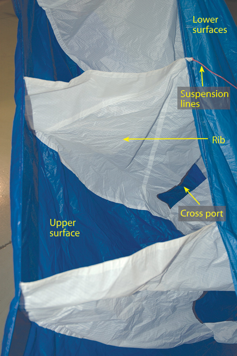
Figure 3-10. Canopy cross-section.
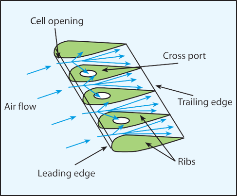
Figure 3-11. Airflow into the wing.
At first sight, the suspension lines on the powered parachute wing might appear like an unorganized wad of strings. On the contrary, each line has a distinct purpose and each line has distinct properties. The suspension lines are sometimes designated A through D and differ between manufacturers; check your POH to know the line labels for your PPC. [Figure 3-12] The front suspension lines are located at the leading edge and the steering lines connect to the trailing edge.
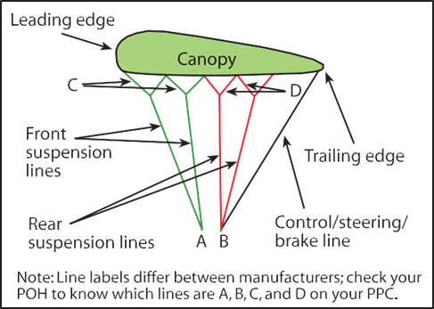
Figure 3-12. Front and rear suspension lines.
The suspension lines come together at a point where they connect with the riser. (The risers are the connection between the suspension lines and the cart.) Many manufacturers color-code the wing suspension lines to assist the pilot in their preflight inspection and lay-out of the wing prior to inflation. [Figure 3-12]
Suspension lines must be constructed of very strong materials, yet remain very small in profile to reduce parasite drag. The most commonly used materials are polyaramid and polyethylene, which are both carbon-based.Kevlar® is a common polyaramid used for suspension lines. Its properties render it extremely strong, as well as resistant to stretching or shrinking, and it is not susceptible to temperature changes. However, one critical drawback of polyaramids is that they tend to kink or knot when looped around. When polyaramids are used to construct suspension lines, they are encased in the skin of a terylene product, like Dacron®, or a product with similar properties. Polyethylene materials, such as Spectra®, Dyneema® or Technora®, are very strong as well as more flexible than polyaramids, which makes them more durable under hard use. However, polyethylene materials are more likely to stretch or shrink, and they are more susceptible to temperature changes. If your wing is equipped with polyethylene suspension lines, it is imperative you do not store your equipment in a place that might experience extreme temperatures. The POH or owner manual provided by the chute manufacturer will specify limits for temperature and storage.
Every line on the powered parachute wing is precisely measured and fitted to a specific location. Therefore, it is imperative to inspect the wing during preflight, in addition to having the wing and its lines inspected periodically by qualified technicians. The technician will conduct strength tests as well as look for wear and compromised attachment points; refer to your wing manufacturer’s specifications for inspection parameters. Under no circumstances should powered parachute suspension lines be spliced or tied if severed! Each line’s length and strength is specifically calibrated. If you tie a knot in the line you will change the specifically-engineered flight characteristics of the wing, rendering it unairworthy.
Risers
Also known as “V lines,” the risers are the intermediate link between the suspension lines and the airframe or the attachment point of the wing to the airframe.
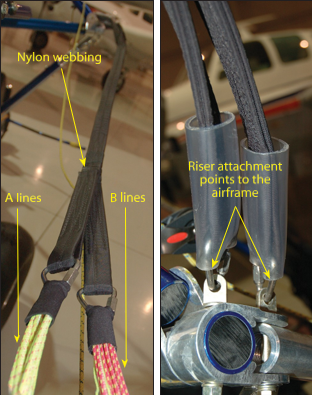
Figure 3-13. The risers are constructed of nylon webbing that takes on the appearance of two straps incorporating a main cable and a safety cable as one unit.
The risers are generally constructed of webbing, which takes on the appearance of two straps that incorporate a main cable and a safety cable as one unit. [Figure 3-13] Some of the older designs of wings may have braided wire cables serving as their risers. The risers are connected to the suspension lines and to the aircraft with various connections such as with D-rings and eyebolts.
During flight, as discussed in Chapter 2, propeller-driven aircraft are affected by the rotation of engine components and the propeller. This is commonly referred to as the “left turning tendency,” which includes torque and sometimes P factor. There are several design features that have been incorporated into airplanes to counteract the left-turning tendency from a clockwise turning propeller. Powered parachute designers can counteract the turning effect by changing the length of the riser cables on one side of the airframe. By decreasing the length of the right riser cable, the wing is given a slight right turn, just enough to cancel the effects of torque at cruise thrust settings. This design feature of the powered parachute wing risers makes it imperative not to mistakenly attach the different length riser cables on the wrong side of the airframe. Remember: the left main and the left safety cables, from the pilot’s seat, are longer than the right main and the right safety cables. Mixing the right and the left cables will result in a pronounced left turn; especially during takeoff when the engine is at full throttle, which could jeopardize the safety of all concerned.
Engine installations with a counterclockwise rotating propeller require opposite adjustments. It is important to know which direction the propeller turns for your PPC to accurately counter turning tendencies.
Alternately, the wing could have the same length risers, and the cart could have a higher attachment point for the left riser. This is why each wing is designed for each cart and should not be interchanged: the wing and the cart is a complete system.
The Fuel Tank
The powered parachute is usually equipped with fuel tanks ranging in capacity from 5 to 20 gallons. As with any aircraft, knowing how much fuel your fuel tank holds is crucial to flight operations. The light-sport aircraft-powered parachute has no limitations as to the size of the fuel tank, unlike its ultralight vehicle predecessor. Most PPC powerplants require auto fuel mid-grade or higher to be burned (see the powerplant operating handbook for specific engine specifications).
Generally, the fuel tank is located close to the center of gravity, so fuel burn does not affect the balance of the aircraft. Some fuel tanks are clear for visual inspection of the amount of fuel onboard while others are dark. Dark tanks or hidden tanks generally have a sight tube to assist the pilot in determining the actual amount of fuel. [Figure 3-14] Some powered parachute manufacturers offer optional fuel level probes and instrument panel analog gauges or incorporate this information into the EIS. As fuel is used by the engine, air needs to enter the tank and take its place; otherwise, a vacuum will form inside the fuel tank preventing the fuel pump from drawing fuel. This is usually accomplished with a fuel venting system. This can be a vent in the fuel cap or some other means that vents elsewhere, providing the ability for the fuel tank to breathe. Any vent system must be free of debris or it will cause fuel starvation in flight. This is especially true when a small hole is in the fuel cap that can be easily plugged. Check the fuel venting system during each preflight inspection.
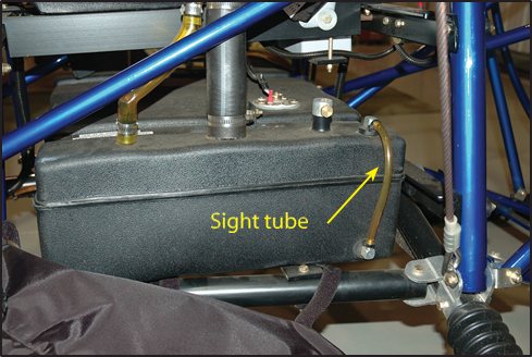
Figure 3-14. Fuel tank with sight tube.
The fuel shut-off valve can be located anywhere in the fuel line. It is important to make sure the fuel valve is open and stays open for normal operation. Most designs have a fuel tank sump drain valve to remove water and solid contaminants. Each design is different and the PPC POH will specify how to conduct this check.
Throttle System
The throttle is the pilot’s hand control to regulate the power provided by the engine. The configuration of the throttle control varies from one cart manufacturer to another. Refer to the POH of each individual PPC for function reference. [Figure 3-15].
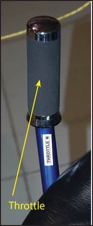
Figure 3-15. Powered parachute throttle.
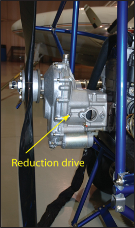
Figure 3-16. Reduction drives reduce the propeller RPM from the engine RPM by about half.
The Powerplant
The typical powered parachute engine can be two- or four-stroke, liquid- or air-cooled, 50 to 100 horsepower- er. Some engines have electric starters and some have pull starters. Most PPC engines have reduction drives that, when attached, reduce the propeller RPM to half to one-quarter of the engine RPM. [Figure 3-16] The engines are as varied as the powered parachutes they power. Modern technology has allowed the powered parachute engine to become lighter, more efficient, and, most importantly, dependable. Chapter 4 covers the powerplant in more detail.
The Propeller
Propellers are “power converters” that change the engine horsepower into “thrust.” Thrust is the force that propels the aircraft through the air by pushing the powered parachute forward. Aerodynamically speaking, a propeller is a rotating airfoil and the same principles that apply to the wing will apply to the propeller. [Figure 3-17] Engine power is transferred to the propeller through a rotating crankshaft that turns the propeller through the air, producing thrust in the same way as wings produce lift. The shape of the blade creates thrust vectors because it is cambered like the air-foil of a wing. Consequently, as the air flows past the propeller, the pressure on one side is less than that on the other. As in a wing, this produces a reaction force in the direction of the lower pressure. In the case of the propeller, which is mounted in a vertical plane, the
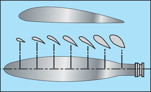
Figure 3-17. Airfoil sections of a propeller blade.
area of decreased pressure is in front of the propeller, and the force (thrust) is in a forward direction. Aerodynamically, the thrust is the result of the propeller shape and the angle of attack of the blade.
The typical powered parachute has a ground-adjustable propeller. The adjustment of the propeller should only be conducted to meet the engine manufacturer’s maximum recommended RPM target. Pilots who are not familiar with adjusting the propeller and how it will affect the PPC performance should consult with a knowledgeable source prior to making any propeller adjustments.
The engine mount is designed by individual manufacturers for each cart configuration. The majority of the total aircraft weight is determined by the engine and mounting configuration. When trailering the PPC over bumpy terrain or over long trips, the bouncing of the cart in the trailer can put extreme stress on this mounting system. In addition, repeated hard landings of the cart can also stress the welds of the engine mount. Consistently detailed inspections of the engine mount should be an important part of every preflight and post-flight inspection.
Just like an airplane propeller, the powered parachute propeller turns at such great speeds that it becomes invisible when in motion. The dangers of a turning propeller require every pilot to maintain the highest level of safety and respect for the consequences of body parts, pets, and debris coming in contact with a rotating propeller. Always treat the propeller as if the ignition were on. Debris on the takeoff/landing field is a danger to the propeller as well as to the people who may be in the prop-wash area behind the propeller. Stones, small pieces of metal, and sticks can become dangerous projectiles if kicked into the propeller during takeoff and landing. Just as with any airframe or wing component of a powered parachute, if the propeller becomes damaged, nicked or dinged, the aircraft’s performance can be greatly affected.
Some pilots elect to use tape or rock deflector guards to protect the leading edge from rock/debris damage. Regardless, taking proper care of the PPC propeller is as critical as proper engine and wing care.
Axle and Wheel Assembly
The rear and front wheels of the powered parachute are an assembly and consist of a tire, a rim, and an inner and outer set of wheel bearings. The wheel is secured on a spindle and held in place by a nut and a cotter pin. Each spindle is typically mounted on a suspension system which provides elasticity and at the same time is very strong. [Figure 3-18] The suspension system varies by manufacturer from one cart to another; refer to the POH for exact configuration and components. Some powered parachute tires are heavily treaded while others are smooth; pilot preference and the terrain type are determining factors in the choice of tire profiles. [Figure 3-19] Tire sealant or thorn guards can be used to minimize flat tires.
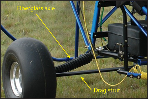
Figure 3-18. Suspension system.
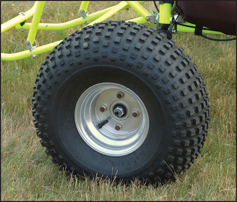
Figure 3-19. Some powered parachute tires are heavily treaded while others are smooth.


