Introduction
This chapter discusses general planning and conduct of instrument approaches by pilots operating under Title 14 of the Code of Federal Regulations (14 CFR) Parts 91,121, 125, and 135. The operations specifications (OpSpecs), standard operating procedures (SOPs), and any other FAA- approved documents for each commercial operator are the final authorities for individual authorizations and limitations as they relate to instrument approaches. While coverage of the various authorizations and approach limitations for all operators is beyond the scope of this chapter, an attempt is made to give examples from generic manuals where it is appropriate.
Approach Planning
Depending on speed of the aircraft, availability of weather information, and the complexity of the approach procedure or special terrain avoidance procedures for the airport of intended landing, the in-flight planning phase of an instrument approach can begin as far as 100-200 NM from the destination. Some of the approach planning should be accomplished during preflight. In general, there are five steps that most operators incorporate into their flight standards manuals for the in-flight planning phase of an instrument approach:
- Gathering weather information, field conditions, and Notices to Airmen (NOTAMs) for the airport of intended landing.
- Calculation of performance data, approach speeds, and thrust/power settings.
- Flight deck navigation/communication and automation setup.
- Instrument approach procedure (IAP) review and, for flight crews, IAP briefing.
- Operational review and, for flight crews, operational briefing.
Although often modified to suit each individual operator, these five steps form the basic framework for the in-flight planning phase of an instrument approach. The extent of detail that a given operator includes in their SOPs varies from one operator to another; some may designate which pilot performs each of the above actions, the sequence, and the manner in which each action is performed. Others may leave much of the detail up to individual flight crews and only designate which tasks should be performed prior to commencing an approach. Flight crews of all levels, from single-pilot to multi-crewmember Part 91 operators, can benefit from the experience of commercial operators in developing techniques to fly standard instrument approach procedures (SIAPs).
Determining the suitability of a specific IAP can be a very complex task, since there are many factors that can limit the usability of a particular approach. There are several questions that pilots need to answer during preflight planning and prior to commencing an approach. Is the approach procedure authorized for the company, if Part 91, subpart K, 121, 125, or 135? Is the weather appropriate for the approach? Is the aircraft currently at a weight that will allow it the necessary performance for the approach and landing or go around/ missed approach? Is the aircraft properly equipped for the approach? Is the flight crew qualified and current for the approach? Many of these types of issues must be considered during preflight planning and within the framework of each specific air carrier’s OpSpecs, or Part 91.
Weather Considerations
Weather conditions at the field of intended landing dictate whether flight crews need to plan for an instrument approach and, in many cases, determine which approaches can be used, or if an approach can even be attempted. The gathering of weather information should be one of the first steps taken during the approach-planning phase. Although there are many possible types of weather information, the primary concerns for approach decision-making are windspeed, wind direction, ceiling, visibility, altimeter setting, temperature, and field conditions. It is also a good idea to check NOTAMs at this time, in case there were any changes since preflight planning.
Windspeed and direction are factors because they often limit the type of approach that can be flown at a specific location. This typically is not a factor at airports with multiple precision approaches, but at airports with only a few or one approach procedure, the wrong combination of wind and visibility can make all instrument approaches at an airport unavailable. Pilots must be prepared to execute other available approaches, not just the one that they may have planned for. As an example, consider the available approaches at the Chippewa Valley Regional Airport (KEAU) in Eau Claire, Wisconsin. [Figure 4-1] In the event that the visibility is reported as less than one mile, the only useable approaches for Category C aircraft is the Instrument Landing System (ILS) and Lateral navigation (LNAV)/vertical navigation (VNAV) to Runway 22. This leaves very few options for flight crews if the wind does not favor Runway 22; and, in cases where the wind restricts a landing on that runway altogether, even a circling approach cannot be flown because of the visibility.
Weather Sources
Most of the weather information that flight crews receive is issued to them prior to the start of each flight segment, but the weather used for in-flight planning and execution of an instrument approach is normally obtained en route via government sources, company frequency, or Aircraft Communications Addressing and Reporting System (ACARS).
Air carriers and operators certificated under the provisions of Part 119 (Certification: Air Carriers and Commercial Operators) are required to use the aeronautical weather information systems defined in the OpSpecs issued to that certificate holder by the FAA. These systems may use basic FAA/National Weather Service (NWS) weather services, contractor or operator-proprietary weather services, and/
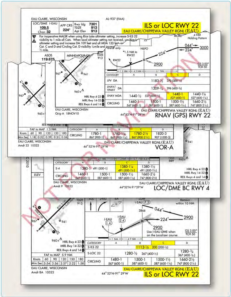
Figure 4-1. Chippewa Regional Airport (KEAU), Eau Claire, Wisconsin.
or Enhanced Weather Information System (EWINS) when approved in the OpSpecs. As an integral part of EWINS approval, the procedures for collecting, producing, and disseminating aeronautical weather information, as well as the crewmember and dispatcher training to support the use of system weather products, must be accepted or approved.
Operators not certificated under the provisions of 14 CFR Part 119 are encouraged to use FAA/NWS products through the Flight Service Stations (FSS). FSS provide pilot weather briefings, en route weather, receive and process instrument flight rule (IFR) and visual flight rule (VFR) flight plans, relay air traffic control (ATC) clearances, and issue NOTAMs. They also provide assistance to lost aircraft and aircraft in emergency situations and conduct VFR search and rescue services.
Direct User Access Terminal System (DUATS), funded by the FAA, allows any pilot to access weather information and file a flight plan via computer. Two contract vendors currently provide information services within the DUATS system, and can be accessed via the Internet at www.duats.com or www.1800wxbrief.com. The current vendors of DUATS II service and the associated phone numbers are listed in Chapter 7 of the Aeronautical Information Manual (AIM).
Flight Information Service—Broadcast (FIS-B) provides certain aviation weather and other aeronautical information to aircraft equipped with an appropriate flight deck display. Reception of FIS-B services can be expected within a ground station coverage volume when line-of-sight geometry is maintained between the aircraft and ground station. National Airspace System (NAS) wide service availability was targeted for 2013 and is currently available within certain regions. FIS-B provides the following textual and graphical aviation weather and aeronautical products free-of-charge. A detailed description of these products can be found in the AIM.
- Aviation Digital Data Services (ADDS) provides the aviation community with text, digital and graphical forecasts, analyses, and observations of aviation related weather variables. ADDS is a joint effort of National Oceanic and Atmospheric Administration’s (NOAA) Earth System Research Laboratory, National Center for Atmospheric Research (NCAR) Research Applications Laboratory (RAL), and the Aviation Weather Center (AWC).
Hazardous In-flight Weather Advisory Service (HIWAS) is a national program for broadcasting hazardous weather information continuously over selected navigation aids (NAVAIDs). The broadcasts include advisories such as Airman’s Meteorological Information (AIRMETs), Significant Meteorological Information (SIGMETs), convective SIGMETs, and urgent pilot weather reports (PIREPs/UUA). These broadcasts are only a summary of the information, and pilots should contact an FSS for detailed information.
- Telephone Information Briefing Service ( TIBS) is a service prepared and disseminated by Flight Service. It provides continuous telephone recordings of meteorological and aeronautical information. Specifically, TIBS provides area and route briefings, as well as airspace procedures and special announcements, if applicable. It is designed to be a preliminary briefing tool and is not intended to replace a standard briefing from a flight service specialist. The TIBS service is available 24 hours a day and is updated when conditions change, but it can only be accessed by a touch tone phone. The phone numbers for the TIBS service are listed in the Chart Supplement, formerly the Airport/Facility Directory (A/FD). TIBS should also contain, but is not limited to: surface observations, terminal aerodrome forecast (TAFs), and winds/temperatures aloft forecasts.
The suite of available aviation weather product types is expanding with the development of new sensor systems, algorithms, and forecast models. The FAA and NWS, supported by the NCAR and the NOAA Forecast Systems Laboratory (FSL), develop and implement new aviation weather product types through a comprehensive process known as the Aviation Weather Technology Transfer process. This process ensures that user needs and technical and operational readiness requirements are met as experimental product types mature to operational application.
The development of enhanced communications capabilities, most notably the internet, has allowed pilots access to an increasing range of weather service providers and proprietary products. It is not the intent of the FAA to limit operator use of this weather information. However, pilots and operators should be aware that weather services provided by entities other than the FAA, NWS, or their contractors (such as the DUATS and flight information services data link (FISDL) providers) may not meet FAA/ NWS quality control standards.
Broadcast Weather
The most common method used by flight crews to obtain specific in-flight weather information is to use a source that broadcasts weather for the specific airport. Information about ceilings, visibility, wind, temperature, barometric pressure, and field conditions can be obtained from most types of broadcast weather services. Broadcast weather can be transmitted to the aircraft in radio voice format or digital format, if it is available, via an ACARS system.
Automated Terminal Information Service (ATIS)
Automatic terminal information service (ATIS) is the continuous broadcast of recorded non-control information in selected high activity terminal areas. Its purpose is to improve controller effectiveness and to relieve frequency congestion by automating the repetitive transmission of essential but routine information. The information is continuously broadcast over a discrete very high frequency (VHF) radio frequency or the voice portion of a local NAVAID. ATIS transmissions on a discrete VHF radio frequency are engineered to be receivable to a maximum of 60 NM from the ATIS site and a maximum altitude of 25,000 feet above ground level (AGL). At most locations, ATIS signals may be received on the surface of the airport, but local conditions may limit the maximum ATIS reception distance and/or altitude. Pilots are urged to cooperate in the ATIS program as it relieves frequency congestion on approach control, ground control, and local control frequencies. The CS indicates airports for which ATIS is provided.
ATIS information includes the time of the latest weather sequence, ceiling, visibility, obstructions to visibility, temperature, dew point (if available), wind direction (magnetic), velocity, altimeter, other pertinent remarks, instrument approach and runway in use. The ceiling/sky condition, visibility, and obstructions to vision may be omitted from the ATIS broadcast if the ceiling is above 5,000 feet and the visibility is more than five miles. The departure runway will only be given if different from the landing runway except at locations having a separate ATIS for departure. The broadcast may include the appropriate frequency and instructions for VFR arrivals to make initial contact with approach control. Pilots of aircraft arriving or departing the terminal area can receive the continuous ATIS broadcast at times when flight deck duties are least pressing and listen to as many repeats as desired. ATIS broadcast will be updated upon the receipt of any official hourly and special weather. A new recording will also be made when there is a change in other pertinent data, such as runway change and instrument approach in use.
Automated Weather Observing Programs
Automated weather reporting systems are increasingly being installed at airports. These systems consist of various sensors, a processor, a computer-generated voice subsystem, and a transmitter to broadcast local, minute• by-minute weather data directly to the pilot.
Automated Weather Observing System
The automated weather observing system (AWOS) observations include the prefix “AUTO” to indicate that the data are derived from an automated system. Some AWOS locations are augmented by certified observers who provide weather and obstruction to vision information in the remarks of the report when the reported visibility is less than seven miles. These sites, along with the hours of augmentation, are published in the CS. Augmentation is identified in the observation as “OBSERVER WEATHER.” The AWOS wind speed, direction and gusts, temperature, dew point, and altimeter setting are exactly the same as for manual observations. The AWOS also reports density altitude when it exceeds the field elevation by more than 1,000 feet. The reported visibility is derived from a sensor near the touchdown of the primary instrument runway. The visibility sensor output is converted to a visibility value using a 10-minute harmonic average. The reported sky condition/ ceiling is derived from the ceilometer located next to the visibility sensor. The AWOS algorithm integrates the last 30 minutes of ceilometer data to derive cloud layers and heights. This output may also differ from the observer sky condition in that the AWOS is totally dependent upon the cloud advection over the sensor site.
Automated Surface Observing System (ASOS)/ Automated Weather Sensor System (AWSS)
The automated surface observing system (ASOS)/ automated weather sensor system (AWSS) is the primary surface weather observing system of the United States. The program to install and operate these systems throughout the United States is a joint effort of the NWS, the FAA, and the Department of Defense (DOD). AWSS is a follow-on program that provides identical data as ASOS. ASOS/AWSS is designed to support aviation operations and weather forecast activities. The ASOS/ AWSS provides continuous minute-by-minute observations and performs the basic observing functions necessary to generate a aviation routine weather report (METAR) and other aviation weather information. The information may be transmitted over a discrete VHF radio frequency or the voice portion of a local NAVAID. ASOS/AWSS transmissions on a discrete VHF radio frequency are engineered to be receivable to a maximum of 25 NM from the ASOS/AWSS site and a maximum altitude of 10,000 feet AGL. At many locations, ASOS/AWSS signals may be received on the surface of the airport, but local conditions may limit the maximum reception distance and/or altitude. While the automated system and the human may differ in their methods of data collection and interpretation, both produce an observation quite similar in form and content. For the objective elements, such as pressure, ambient temperature, dew point temperature, wind, and precipitation accumulation, both the automated system and the observer use a fixed location and time-averaging technique. The quantitative differences between the observer and the automated observation of these elements are negligible. For the subjective elements; however, observers use a fixed time (spatial averaging technique) to describe the visual elements (sky condition, visibility, and present weather, etc.), while the automated systems use a fixed location and time averaging technique. Although this is a fundamental change, the manual and automated techniques yield remarkably similar results within the limits of their respective capabilities.
The use of the aforementioned visibility reports and weather services are not limited for Part 91 operators. Part 121 and 135 operators are bound by their individual OpSpecs documents and are required to use weather reports that come from the NWS or other approved sources. While all OpSpecs are individually tailored, most operators are required to use ATIS information, runway visual range (RVR) reports, and selected reports from automated weather stations. All reports coming from an AWOS-3 station are usable for Part 121 and 135 operators. Each type of automated station has different levels of approval as outlined in individual OpSpecs. Ceiling and visibility reports given by the tower with the departure information are always considered official weather, and RVR reports are typically the controlling visibility reference. Refer to Chapter 1, Departures, of this manual, as well as the AIM section 7-1-12 for further description of automated weather systems.
Center Weather Advisories (CWA)
Center weather advisories (CWAs) are unscheduled inflight, flow control, air traffic, and aircrew advisories. By nature of its short lead time, the CWA is not a flight planning product. It is generally a nowcast for conditions beginning in the next two hours. CWAs will be issued:
- As a supplement to an existing SIGMET, convective SIGMET, or AIRMET.
- When an in-flight advisory has not been issued but observed or expected weather conditions meet SIGMET/AIRMET criteria based on current pilot reports and reinforced by other sources of information about existing meteorological conditions.
- When observed or developing weather conditions do not meet SIGMET, convective SIGMET, or AIRMET criteria (e.g., in terms of intensity or area coverage), but current pilot reports or other weather information sources indicate that existing or anticipated meteorological phenomena will adversely affect the safe and efficient flow of air traffic within the ARTCC area of responsibility.
Weather Regulatory Requirements
There are many practical reasons for reviewing weather information prior to initiating an instrument approach. Pilots must familiarize themselves with the condition of individual airports and runways so that they may make informed decisions regarding fuel management, diversions, and alternate planning. Because this information is critical, 14 CFR requires pilots to comply with specific weather minimums for planning and execution of instrument flights and approaches..
Weather Requirements and Part 91 Operators
According to 14 CFR Part 91, § 91.103, the pilot in command (PIC) must become familiar with all available information concerning a flight prior to departure. Included in this directive is the fundamental basis for pilots to review NOTAMs and pertinent weather reports and forecasts for the intended route of flight. This review should include current weather reports and terminal forecasts for all intended points of landing and alternate airports. In addition, a thorough review of an airport’s current weather conditions should always be conducted prior to initiating an instrument approach. Pilots should also consider weather information as a planning tool for fuel management.
For flight planning purposes, weather information must be reviewed in order to determine the necessity and suitability of alternate airports. For Part 91 operations, the 600-2 and 800-2 rule applies to airports with precision and non- precision approaches, respectively. Approaches with vertical guidance (APV) are non-precision approaches because they do not meet the International Civil Aviation Organization (ICAO) Annex 10 standards for a precision approach. (See Final Approach Segment section later in this chapter for more information regarding APV approaches.) Exceptions to the 600-2 and 800-2 alternate minimums are listed in the front of the Aeronautical Information Services in the Terminal Procedures Publication (TPP) and are indicated by a symbol on the approach charts for the airport. This does not preclude flight crews from initiating instrument approaches at alternate airports when the weather conditions are below these minimums. The 600• 2 and 800-2 rules, or any exceptions, only apply to flight planning purposes, while published landing minimums apply to the actual approach at the alternate.
Weather Requirements and Part 135 Operators
Unlike Part 91 operators, Part 135 operators may not depart for a destination unless the forecast weather there will allow an instrument approach and landing. According to 14 CFR Part 135, § 135.219, flight crews and dispatchers may only designate an airport as a destination if the latest weather reports or forecasts, or any combination of them, indicate that the weather conditions will be at or above IFR landing minimums at the estimated time of arrival (ETA). This ensures that Part 135 flight crews consider weather forecasts when determining the suitability of destinations. Departures for airports can be made when the forecast weather shows the airport will be at or above IFR minimums at the ETA, even if current conditions indicate the airport to be below minimums. Conversely, 14 CFR Part 135, § 135.219 prevents departures when the first airport of intended landing is currently above IFR landing minimums, but the forecast weather is below those minimums at the ETA.
Another very important difference between Part 91 and Part 135 operations is the Part 135 requirement for airports of intended landing to meet specific weather criteria once the flight has been initiated. For Part 135, not only is the weather required to be forecast at or above instrument flight rules (IFR) landing minimums for planning a departure, but it also must be above minimums for initiation of an instrument approach and, once the approach is initiated, to begin the final approach segment of an approach. 14 CFR Part 135, § 135.225 states that pilots may not begin an instrument approach unless the latest weather report indicates that the weather conditions are at or above the authorized IFR landing minimums for that procedure. 14 CFR Part 135, § 135.225 provides relief from this rule if the aircraft has already passed the final approach fix (FAF) when the weather report is received. It should be noted that the controlling factor for determining whether or not the aircraft can proceed is reported visibility. RVR, if available, is the controlling visibility report for determining that the requirements of this section are met. The runway visibility value (RVV), reported in statute miles (SM), takes precedent over prevailing visibility. There is no required timeframe for receiving current weather prior to initiating the approach.
Weather Requirements and Part 121 Operators
Like Part 135 operators, flight crews and dispatchers operating under Part 121 must ensure that the appropriate weather reports or forecasts, or any combination thereof, indicate that the weather will be at or above the authorized minimums at the ETA at the airport to which the flight is dispatched (14 CFR Part 121, § 121.613). This regulation attempts to ensure that flight crews will always be able to execute an instrument approach at the destination airport. Of course, weather forecasts are occasionally inaccurate; therefore, a thorough review of current weather is required prior to conducting an approach. Like Part 135 operators, Part 121 operators are restricted from proceeding past the FAF of an instrument approach unless the appropriate IFR landing minimums exist for the procedure. In addition, descent below the minimum descent altitude (MDA), decision altitude (DA), or decision height (DH) is governed, with one exception, by the same rules that apply to Part 91 operators. The exception is that during Part 121 and 135 operations, the airplane is also required to land within the touchdown zone (TDZ). Refer to the section titled Minimum Descent Altitude, Decision Altitude, and Decision Height later in this chapter for more information regarding MDA, DA, and DH.
Aircraft Performance Considerations
All operators are required to comply with specific airplane performance limitations that govern approach and landing. Many of these requirements must be considered prior to the origination of flight. The primary goal of these performance considerations is to ensure that the aircraft can remain clear of obstructions throughout the approach, landing, and go- around phase of flight, as well as land within the distance required by the FAA. Although the majority of in-depth performance planning for an instrument flight is normally done prior to the aircraft’s departure, a general review of performance considerations is usually conducted prior to commencing an instrument approach.
Aircraft Performance Operating Limitations Generally speaking, air carriers must have in place an approved method of complying with Subpart I of 14 CFR Parts 121 and 135 (Airplane Performance Operating Limitations), thereby proving the airplane’s performance capability for every flight that it intends to make. Flight crews must have an approved method of complying with the approach and landing performance criteria in the applicable regulations prior to departing for their intended destination. The primary source of information for performance calculations for all operators, including Part 91, is the approved Aircraft Flight Manual (AFM) or Pilot’s Operating Handbook (POH) for the make and model of aircraft that is being operated. It is required to contain the manufacturer determined performance capabilities of the aircraft at each weight, altitude, and ambient temperature that are within the airplane’s listed limitations. Typically, the AFM for a large turbine powered aircraft should contain information that allows flight crews to determine that the aircraft will be capable of performing the following actions, considering the landing weight and other pertinent environmental factor:
- Land within the distance required by the regulations.
- Climb from the missed approach point (MAP) and maintain a specified climb gradient with one engine inoperative.
- Perform a go-around from the final stage of landing and maintain a specified climb gradient with all engines operating and the aircraft in the landing configuration.
Many airplanes have more than one allowable flap configuration for normal landing. Often, a reduced flap setting for landing allows the airplane to operate at a higher landing weight into a field that has restrictive obstacles in the missed approach or rejected landing climb path. On these occasions, the full-flap landing speed may not allow the airplane enough energy to successfully complete a go-around and avoid any high terrain and/or obstacles that might exist on the climb out. Therefore, all-engine and engine-out missed approaches, as well as rejected landings, must be taken into consideration in compliance with the regulations.
Aircraft Approach Categories
Aircraft approach category means a grouping of aircraft based on a reference landing speed (VREF), if specified, or if VREF is not specified, 1.3 VSO at the maximum certified landing weight. VREF, VSO, and the maximum certified landing weight are those values as established for the aircraft by the certification authority of the country of registry. A pilot must use the minima corresponding to the category determined during certification or higher. Helicopters may use Category A minima. If it is necessary to operate at a speed in excess of the upper limit of the speed range for an aircraft’s category, the minimums for the higher category must be used. For example, an airplane that fits into Category B, but is circling to land at a speed of 145 knots, must use the approach Category D minimums. As an additional example, a Category A aircraft that is operating at 130 knots on a straight-in approach must use the approach Category C minimums. See the following category limits noting that the airspeeds depicted are indicated airspeeds (IAS):
- Category A: Speed less than 91 knots.
- Category B: Speed 91 knots or more but less than 121 knots.
- Category C: Speed 121 knots or more but less than 141 knots.
- Category D: Speed 141 knots or more but less than 166 knots.
- Category E: Speed 166 knots or more.
Note: Helicopter pilots may use the Category A line of minimums provided the helicopter is operated at Category A airspeeds.
An airplane is certified in only one approach category, and although a faster approach may require higher category minimums to be used, an airplane cannot be flown to the minimums of a slower approach category. The certified approach category is permanent and independent of the changing conditions of day-to-day operations. From a TERPS viewpoint, the importance of a pilot not operating an aircraft at a category line of minimums lower than the aircraft is certified for is primarily the margin of protection provided for containment of the aircraft within the procedure design for a slower aircraft. This includes height loss at the decision altitude, missed approach climb surface, and turn containment in the missed approach at the higher category speeds.
Pilots are responsible for determining if a higher approach category applies. If a faster approach speed is used that places the aircraft in a higher approach category, the minimums for the appropriate higher category must be used. Emergency returns at weights in excess of maximum certificated landing weight, approaches made with inoperative flaps, and approaches made in icing conditions for some airplanes are examples of situations that can necessitate the use of higher approach category minima.
Circling approaches are one of the most challenging flight maneuvers conducted in the NAS, especially for pilots of CAT C and CAT D turbine-powered, transport category airplanes. These maneuvers are conducted at low altitude, day and night, and often with precipitation present affecting visibility, depth perception, and the ability to adequately assess the descent profile to the landing runway. Most often, circling approaches are conducted to runways without the benefit of electronic navigation aids to support the descent from the Circling Minimums Decision Altitude (CMDA) to the runway.
Circling approaches conducted at faster-than-normal, straight-in approach speeds also require a pilot to consider the larger circling approach area, since published circling minimums provide obstacle clearance only within the appropriate area of protection and is based on the approach category speed. [Figure 4-2] The circling approach area is the obstacle clearance area for aircraft maneuvering to land on a runway that does not meet the criteria for a straight- in approach. The size of the circling area varies with the approach category of the aircraft, as shown in Figure 4-2.
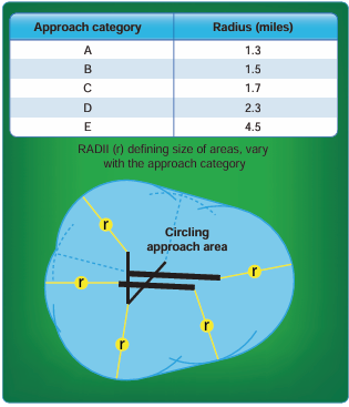
Figure 4-2. Construction of circling approach area.
A minimum of 300 feet of obstacle clearance is provided in the circling segment. Pilots should remain at or above the circling altitude until the aircraft is continuously in a position from which a descent to a landing on the intended runway can be made at a normal rate of descent and using normal maneuvers. Since an approach category can make a difference in the approach and weather minimums and, in some cases, prohibit flight crews from initiating an approach, the approach speed should be calculated and the effects on the approach determined and briefed in the preflight planning phase, as well as reviewed prior to commencing an approach.
Prior to FAA Order 8260.3 Change 21, pilots were often faced with the challenge of descending using a stabilized approach concept if the CMDA height above airport (HAA) exceeded 1,200 feet. Once the HAA approached 1,200 feet, pilots were often forced to increase their rates of descent in order to arrive at the appropriate “in-slot” position. “In-slot” being defined as at a minimum, a CAT C or CAT D turbine-powered airplane should be wings level on a three degree – 318 ft/NM descent path not less than 1 NM from the touchdown point (1,000 feet beyond runway threshold). This was due to the small size of the circling protected airspace that the aircrews must remain within to ensure obstacle clearance.
The FAA Order 8260.3 Change 21 to the circling protected airspace afforded much greater obstacle protection. However, it also afforded the pilot the opportunity to use the extra protected airspace to mitigate the need to conduct a high descent rate, unstabilized approach that was often necessary as a result of the previous criteria for the Circling Approach Radius (CAR). For example, under FAA Order 8260.3 Change 21, a sea level airport with a 1,500 ft HAA will have CAT C CAR of 2.86 NM, a 1.16 NM (68.5%) increase over pre-Change 21 CAR for CAT C. This extra protected airspace can be used by the pilot to maneuver the aircraft instead of being forced to use high descent rates which are often necessary for high HAA circling approaches.
Most commercial operators dictate standard procedures for conducting instrument approaches in their FAA-approved manuals. These standards designate company callouts, flight profiles, configurations, and other specific duties for each flight deck crewmember during the conduct of an instrument approach.
Instrument Approach Charts
Beginning in February 2000, the FAA began issuing the current format for instrument approach charts. This chart was developed by the Department of Transportation (DOT), Volpe National Transportation Systems Center and is commonly referred to as the Pilot Briefing Information format. The FAA chart format is presented in a logical order, facilitating pilot briefing of the procedures. [Figure 4-3]
Approach Chart Naming Conventions
Individual FAA charts are identified on both the top and bottom of the page by their procedure name (based on the NAVAIDs required for the final approach), runway served, and airport location. The identifier for the airport is also listed immediately after the airport name. [Figure 4-4]
There are several types of approach procedures that may cause some confusion for flight crews unfamiliar with the naming conventions. Although specific information about each type of approach is covered later in this chapter, listed below are a few procedure names that can cause confusion.
Straight-In Procedures
When two or more straight-in approaches with the same type of guidance exist for a runway, a letter suffix is added to the title of the approach so that it can be more easily identified. These approach charts start with the letter Z and continue in reverse alphabetical order. For example, consider the (RNAV) (GPS) Z RWY 13C and RNAV (RNP) Y RWY 13C approaches at Chicago Midway International Airport. [Figure 4-5] Although these two approaches can be flown with a global positioning system (GPS) to the
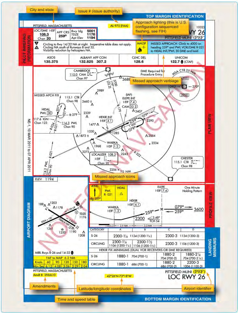
Figure 4-3. Instrument approach chart.
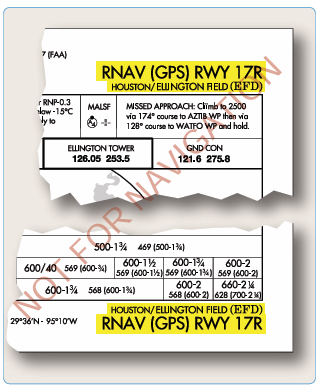
Figure 4-4. Procedure identification.
same runway, they are significantly different (e.g., one is a Required Navigation Performance (RNP) Authorization Required (AR) formally known as SPECIAL AIRCRAFT & AIRCREW AUTHORIZATION REQUIRED (SAAAR);” one has
circling minimums and the other does not; the minimums are different; and the missed approaches are not the same). The approach procedure labeled Z has lower landing minimums than Y (some older charts may not reflect this).
In this example, the LNAV MDA for the RNAV (GPS) Z RWY 13C has the lowest minimums of either approach due to the differences in the final approach required obstacle clearance (ROC) evaluation. This convention also eliminates any confusion with approach procedures labeled A and B, where only circling minimums are published. The designation of two area navigation (RNAV) procedures to the same runway can occur when it is desirable to accommodate panel mounted GPS receivers and flight management systems (FMSs), both with and without vertical navigation (VNAV). It is also important to note that only one of each type of approach for a runway, including ILS, VHF omnidirectional range (VOR), and non-directional beacon (NDB) can be coded into a database.
Circling-Only Procedures
Approaches that do not have straight-in landing minimums are identified by the type of approach followed by a letter. Examples in Figure 4-6 show four procedure titles at the same airport that have only circling minimums.
As can be seen from the example, the first approach of this type created at the airport is labeled with the letter A, and the lettering continues in alphabetical order. Typically, circling only approaches are designed for one of the following reasons:
- The final approach course alignment with the runway centerline exceeds 30°.
- The descent gradient is greater than 400 ft/NM from the FAF to the threshold crossing height (TCH). When this maximum gradient is exceeded, the circling only approach procedure may be designed to meet the gradient criteria limits. This does not preclude a straight-in landing if a normal descent and landing can be made in accordance with the applicable CFRs.
- A runway is not clearly defined on the airfield.
Communications
The communication strip provided near the top of FAA approach charts gives flight crews the frequencies that they can expect to be assigned during the approach. The frequencies are listed in the logical order of use from arrival to touchdown. Having this information immediately available during the approach reduces the chances of a loss of contact between ATC and flight crews during this critical phase of flight.
It is important for flight crews to understand their responsibilities with regard to communications in the various approach environments. There are numerous differences in communication responsibilities when operating into and out of airports without ATC towers as compared to airports with control towers. Today’s pilots face an increasing range of ATC environments and conflicting traffic dangers, making approach briefing and preplanning more critical. Individual company operating manuals and SOPs dictate the duties for each crewmember.
FAA AC 120-71, Standard Operating Procedures for Flight Deck Crewmembers, contains the following concerning ATC communications: SOPs should state who (Pilot Flying (PF), Pilot Monitoring (PM), Flight Engineer (FE/SO)) handles the radios for each phase of flight, as follows:
- PF makes input to aircraft/autopilot and/or verbally states clearances while PM confirms input is what he or she read back to ATC.
- Any confusion in the flight deck is immediately cleared up by requesting ATC confirmation.
- If any crewmember is off the flight deck, all ATC instructions are briefed upon his or her return. Or,
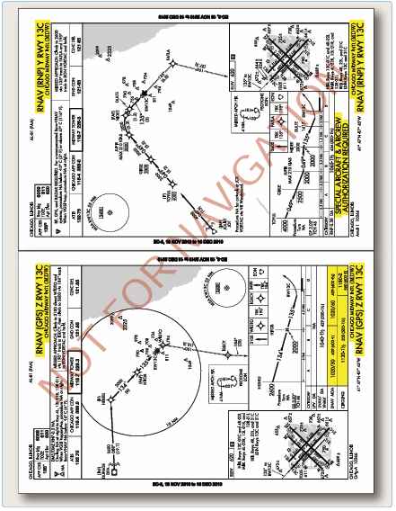
Figure 4-5. Multiple approaches.
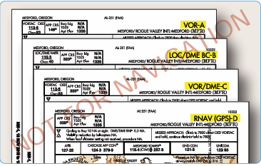
igure 4-6. Procedures with circling landing minima.
if any crewmember is off the flight deck, all ATC instructions are written down until his or her return and then passed to that crewmember upon return. Similarly, if a crewmember is off ATC frequency when making a precision approach (PA) announcement or when talking on company frequency, all ATC instructions are briefed upon his or her return.
- Company policy should address use of speakers, headsets, boom microphone, and/or hand-held microphone.
- SOPs should state the altitude awareness company policy on confirming assigned altitude.
Example: The PM acknowledges ATC altitude clearance. If the aircraft is on the autopilot, then the PF makes input into the autopilot/altitude alerter. PF points to the input while stating the assigned altitude as he or she understands it. The PM then points to the input stating aloud what he or she understands the ATC clearance to be confirming that the input and clearance match. If the aircraft is being hand- flown, then the PM makes the input into the altitude alerter/ autopilot, then points to the input and states clearance. PF then points to the alerter stating aloud what he or she understands the ATC clearance to be confirming that the alerter and clearance match.
Example: If there is no altitude alerter in the aircraft, then both pilots write down the clearance, confirm that they have the same altitude, and then cross off the previously assigned altitude.
Approach Control
Approach control is responsible for controlling all instrument flights operating within its area of responsibility. Approach control may serve one or more airports. Control is exercised primarily through direct pilot and controller communication and airport surveillance radar (ASR). Prior to arriving at the initial approach fix (IAF), instructions will be received from the air route traffic control center (ARTCC) to contact approach control on a specified frequency. Where radar is approved for approach control service, it is used not only for radar approaches, but also for vectors in conjunction with published non-radar approaches using conventional NAVAIDs or RNAV/GPS.
When radar handoffs are initiated between the ARTCC and approach control, or between two approach control facilities, aircraft are cleared (with vertical separation) to an outer fix most appropriate to the route being flown and, if required, given holding instructions. Or, aircraft are cleared to the airport or to a fix so located that the handoff is completed prior to the time the aircraft reaches the fix. When radar handoffs are used, successive arriving flights may be handed off to approach control with radar separation in lieu of vertical separation.
After release to approach control, aircraft are vectored to the final approach course. ATC occasionally vectors the aircraft across the final approach course for spacing requirements. The pilot is not expected to turn inbound on the final approach course unless an approach clearance has been issued. This clearance is normally issued with the final vector for interception of the final approach course, and the vector enables the pilot to establish the aircraft on the final approach course prior to reaching the FAF.
Air Route Traffic Control Center (ARTCC)
ARTCCs are approved for and may provide approach control services to specific airports. The radar systems used by these centers do not provide the same precision as an ASR or precision approach radar (PAR) used by approach control facilities and control towers, and the update rate is not as fast. Therefore, pilots may be requested to report established on the final approach course. Whether aircraft are vectored to the appropriate final approach course or provide their own navigation on published routes to it, radar service is automatically terminated when the landing is completed; or when instructed to change to advisory frequency at airports without an operating ATC tower, whichever occurs first. When arriving on an IFR flight plan at an airport with an operating control tower, the flight plan is closed automatically upon landing.
The extent of services provided by approach control varies greatly from location to location. The majority of Part 121 operations in the NAS use airports that have radar service and approach control facilities to assist in the safe arrival and departure of large numbers of aircraft. Many airports do not have approach control facilities. It is important for pilots to understand the differences between approaches with and without an approach control facility. For example,
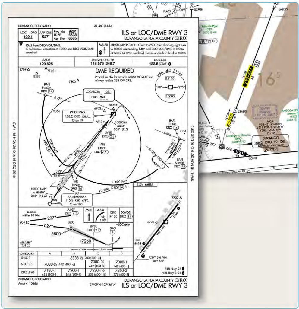
Figure 4-7. Durango approach and low altitude en route excerpt.
consider the Durango, Colorado, ILS DME RWY 2 and low altitude en route chart excerpt shown in Figure 4-7.
High or Lack of Minimum Vectoring Altitudes (MVAs)
Considering the fact that most modern commercial and corporate aircraft are capable of direct, point-to-point flight, it is increasingly important for pilots to understand the limitations of ARTCC capabilities with regard to minimum altitudes. There are many airports that are below the coverage area of Center radar, and; therefore, off-route transitions into the approach environment may require that the aircraft be flown at a higher altitude than would be required for an on-route transition. In the Durango example, an airplane approaching from the northeast on a direct route to the Durango VOR may be restricted to a minimum IFR altitude (MIA) of 17,000 feet MSL due to unavailability of Center radar coverage in that area at lower altitudes. An arrival on V95 from the northeast would be able to descend to a minimum en route altitude (MEA) of 12,000 feet, allowing a shallower transition to the approach environment. An off-route arrival may necessitate a descent into holding in order to avoid an unstable approach to Durango.
Lack of Approach Control Terrain Advisories
Flight crews must understand that terrain clearance cannot be assured by ATC when aircraft are operating at altitudes that are not served by Center or approach radar. Recent National Transportation Safety Board (NTSB) investigations have identified several accidents that involved controlled flight into terrain (CFIT) by IFR rated and VFR pilots operating under visual flight conditions at night in remote areas. In many of these cases, the pilots were in contact with ATC at the time of the accident and receiving radar service. The pilots and controllers involved all appear to have been unaware that the aircraft were in danger. Increased altitude awareness and better preflight planning would likely have prevented all of these accidents. How can pilots avoid becoming involved in a CFIT accident?
CFIT accidents are best avoided through proper preflight planning.
- Terrain familiarization is critical to safe visual operations at night. Use sectional charts or other topographic references to ensure that your altitude safely clears terrain and obstructions all along your route.
- In remote areas, especially in overcast or moonless conditions, be aware that darkness may render visual avoidance of high terrain nearly impossible and that the absence of ground lights may result in loss of horizon reference.
- When planning a nighttime VFR flight, follow IFR practices, such as climbing on a known safe course, until well above surrounding terrain. Choose a cruising altitude that provides terrain separation similar to IFR flights (2,000 feet AGL in mountainous areas and 1,000 feet above the ground in other areas.)When receiving radar services, do not depend on ATC to warn you of terrain hazards. Although controllers try to warn pilots if they notice a hazardous situation, they may not always be able to recognize that a particular VFR aircraft is dangerously close to terrain.
- When issued a heading along with an instruction to “maintain VFR,” be aware that the heading may not provide adequate terrain clearance. If you have any doubt about your ability to visually avoid terrain and obstacles, advise ATC immediately and take action to reach a safe altitude if necessary.
- ATC radar software can provide limited prediction and warning of terrain hazards, but the warning system is configured to protect IFR flights and is normally suppressed for VFR aircraft. Controllers can activate the warning system for VFR flights upon pilot request, but it may produce numerous false alarms for aircraft operating below the MIA, especially in en route center airspace.
- If you fly at night, especially in remote or unlit areas, consider whether a GPS-based terrain awareness unit would improve your safety of flight.
- Lack of approach control traffic advisories—if radar service is not available for the approach, the ability of ATC to give flight crews accurate traffic advisories is greatly diminished. In some cases, the common traffic advisory frequency (CTAF) may be the only tool available to enhance an IFR flight’s awareness of traffic at the destination airport. Additionally, ATC will not clear an IFR flight for an approach until the preceding aircraft on the approach has cancelled IFR, either on the ground, or airborne once in visual meteorological conditions (VMC).
Airports With an ATC Tower
Control towers are responsible for the safe, orderly, and expeditious flow of all traffic that is landing, taking off, operating on and in the vicinity of an airport and, when the responsibility has been delegated, towers also provide for the separation of IFR aircraft in terminal areas. Aircraft that are departing IFR are integrated into the departure sequence by the tower. Prior to takeoff, the tower controller coordinates with departure control to assure adequate aircraft spacing.
Airports Without A Control Tower
From a communications standpoint, executing an instrument approach to an airport that is not served by an ATC tower requires more attention and care than making a visual approach to that airport. Pilots are expected to self-announce their arrival into the vicinity of the airport no later than 10 NM from the field. Depending on the weather, as well as the amount and type of conflicting traffic that exists in the area, an approach to an airport without an operating ATC tower increases the difficulty of the transition to visual flight.
In many cases, a flight arriving via an instrument approach needs to mix in with VFR traffic operating in the vicinity of the field. For this reason, many companies require that flight crews make contact with the arrival airport CTAF or company operations personnel via a secondary radio over 25 NM from the field in order to receive traffic advisories. In addition, pilots should attempt to listen to the CTAF well in advance of their arrival in order to determine the VFR traffic situation.
Since separation cannot be provided by ATC between IFR and VFR traffic when operating in areas where there is no radar coverage, pilots are expected to make radio announcements on the CTAF. These announcements allow other aircraft operating in the vicinity to plan their departures and arrivals with a minimum of conflicts. In addition, it is very important for crews to maintain a listening watch on the CTAF to increase their awareness of the current traffic situation. Flights inbound on an instrument approach to a field without a control tower should make several self-announced radio calls during the approach:
- Initial call within 4-10 minutes of the aircraft’s arrival at the IAF. This call should give the aircraft’s location as well as the crew’s approach intentions.
- Departing the IAF, stating the approach that is being initiated.
- Procedure turn (or equivalent) inbound.
- FAF inbound, stating intended landing runway and maneuvering direction if circling.
- Short final, giving traffic on the surface notification of imminent landing.
When operating on an IFR flight plan at an airport without a functioning control tower, pilots must initiate cancellation of the IFR flight plan with ATC or an AFSS. Remote communications outlets (RCOs) or ground communications outlets (GCOs), if available, can be used to contact an ARTCC or an AFSS after landing. If a frequency is not available on
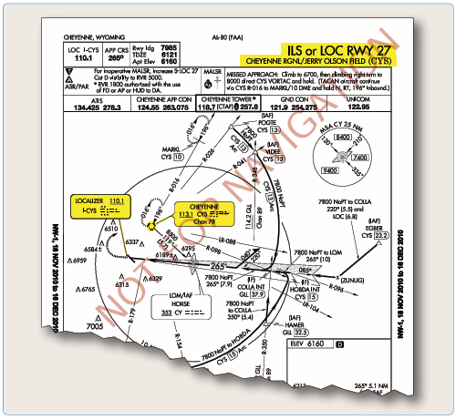
igure 4-8. Cheyenne Regional (KCYS), Cheyenne, Wyoming, ILS or LOC RWY 27.
the ground, the pilot has the option to cancel IFR while in flight if VFR conditions can be maintained while in contact with ARTCC, as long as those conditions can be maintained until landing. Additionally, pilots can relay a message through another aircraft or contact flight service via telephone.
Primary NAVAID
Most conventional approach procedures are built around a primary final approach NAVAID; others, such as RNAV (GPS) approaches, are not. If a primary NAVAID exists for an approach, it should be included in the IAP briefing, set into the appropriate backup or active navigation radio, and positively identified at some point prior to being used for course guidance. Adequate thought should be given to the appropriate transition point for changing from FMS or other en route navigation over to the conventional navigation to be used on the approach. Specific company standards and procedures normally dictate when this changeover occurs; some carriers are authorized to use FMS course guidance throughout the approach, provided that an indication of the conventional navigation guidance is available and displayed. Many carriers, or specific carrier fleets, are required to change over from RNAV to conventional navigation prior to the FAF of an instrument approach.
Depending on the complexity of the approach procedure, pilots may have to brief the transition from an initial NAVAID to the primary and missed approach NAVAIDs. Figure 4-8 shows the Cheyenne, Wyoming, ILS Runway 27 approach procedure, which requires additional consideration during an IAP briefing.
If the 15 DME arc of the CYS VOR is to be used as the transition to this ILS approach procedure, caution must be paid to the transition from en route navigation to the initial NAVAID and then to the primary NAVAID for the ILS approach. Planning when the transition to each of these NAVAIDs occurs may prevent the use of the incorrect NAVAID for course guidance during approaches where high pilot workloads already exist.
Equipment Requirements
The navigation equipment that is required to join and fly an IAP is indicated by the title of the procedure and notes on the chart. Straight-in IAPs are identified by the navigation system by providing the final approach guidance and the runway with which the approach is aligned (for example, VOR RWY 13). Circling-only approaches are identified by the navigation system by providing final approach guidance and a letter (for example, VOR A). More than one navigation system separated by a slant indicates that more than one type of equipment must be used to execute the final approach (for example, VOR/DME RWY 31). More than one navigation system separated by the word“or”indicates either type of equipment can be used to execute the final approach (for example, VOR or GPS RWY 15).
In some cases, other types of navigation systems, including radar, are required to execute other portions of the approach or to navigate to the IAF (for example, an NDB procedure turn to an ILS, or an NDB in the missed approach, or radar required to join the procedure or identify a fix). When ATC radar or other equipment is required for procedure entry from the en route environment, a note is charted in the plan view of the approach procedure chart (for example, RADAR REQUIRED or AUTOMATIC DIRECTION
FINDER (ADF) REQUIRED). When radar or other equipment is required on portions of the procedure outside the final approach segment, including the missed approach, a note is charted in the notes box of the pilot briefing portion of the approach chart (for example, RADAR REQUIRED or DISTANCE MEASURING EQUIPMENT (DME) REQUIRED).
Notes are not charted when VOR is required outside the final approach segment. Pilots should ensure that the aircraft is equipped with the required NAVAIDs to execute the approach, including the missed approach. Refer to the AIM paragraph 5-4-5 for additional options with regards to equipment requirements for IAPs.
RNAV systems may be used as a Substitute Means of Navigation when a very high frequency (VHF) Omni- directional Range (VOR), Distance Measuring Equipment (DME), Tactical Air Navigation ( TACAN), VOR/TACAN (VORTAC), VOR/DME, non-directional radio beacon (NDB), or compass locator facility including locator outer marker and locator middle marker is out-of-service, i.e., the Navigation Aid (NAVAID) information is not available; an aircraft is not equipped with an automatic direction finder (ADF) or DME; or the installed ADF or DME on an aircraft is not operational. For example, if equipped with a suitable RNAV system, a pilot may hold over an out-of-service NDB. Refer to Advisory Circular 90-108, Use of Suitable RNAV System on Conventional Routes and Procedures, dated March 3, 2011 for additional guidance on the proper times and procedures for substituting a RNAV system for means of navigation.
Courses
Traditional Courses
An aircraft that has been cleared to a holding fix and subsequently “cleared…approach,” normally does not receive new routing. Even though clearance for the approach may have been issued prior to the aircraft reaching the holding fix, ATC would expect the pilot to proceed via the holding fix that was the last assigned route, and the feeder route associated with that fix, if a feeder route is published on the approach chart, to the IAF to commence the approach. When cleared for the approach, the published off-airway (feeder) routes that lead from the en route structure to the IAF are part of the approach clearance.
If a feeder route to an IAF begins at a fix located along the route of flight prior to reaching the holding fix, and clearance for an approach is issued, a pilot should commence the approach via the published feeder route. For example, the aircraft would not be expected to overfly the feeder route and return to it. The pilot is expected to commence the approach in a similar manner at the IAF, if the IAF for the procedure is located along the route of flight to the holding fix.
If a route of flight directly to the IAF is desired, it should be so stated by the controller with phraseology to include the words “direct,” “proceed direct,” or a similar phrase that the pilot can interpret without question. When a pilot is uncertain of the clearance, ATC should be queried immediately as to what route of flight is preferred.
The name of an instrument approach, as published, is used to identify the approach, even if a component of the approach aid is inoperative or unreliable. The controller will use the name of the approach as published, but must advise the aircraft at the time an approach clearance is issued that the inoperative or unreliable approach aid component is unusable. (Example: “Cleared ILS RWY 4, glideslope unusable.”)
Area Navigation Courses
RNAV (GPS) approach procedures introduce their own tracking issues because they are flown using an onboard navigation database. They may be flown as coupled approaches or flown manually. In either case, navigation system coding is based on procedure design, including waypoint (WP) sequencing for an approach and missed approach. The procedure design indicates whether the WP is a fly-over (FO) or fly-by (FB), and provides appropriate guidance for each. A FB WP requires the use of turn anticipation to avoid overshooting the next flight segment. A FO WP precludes any turn until the WP is over flown and is followed by either an intercept maneuver of the next flight segment or direct flight to the next WP.
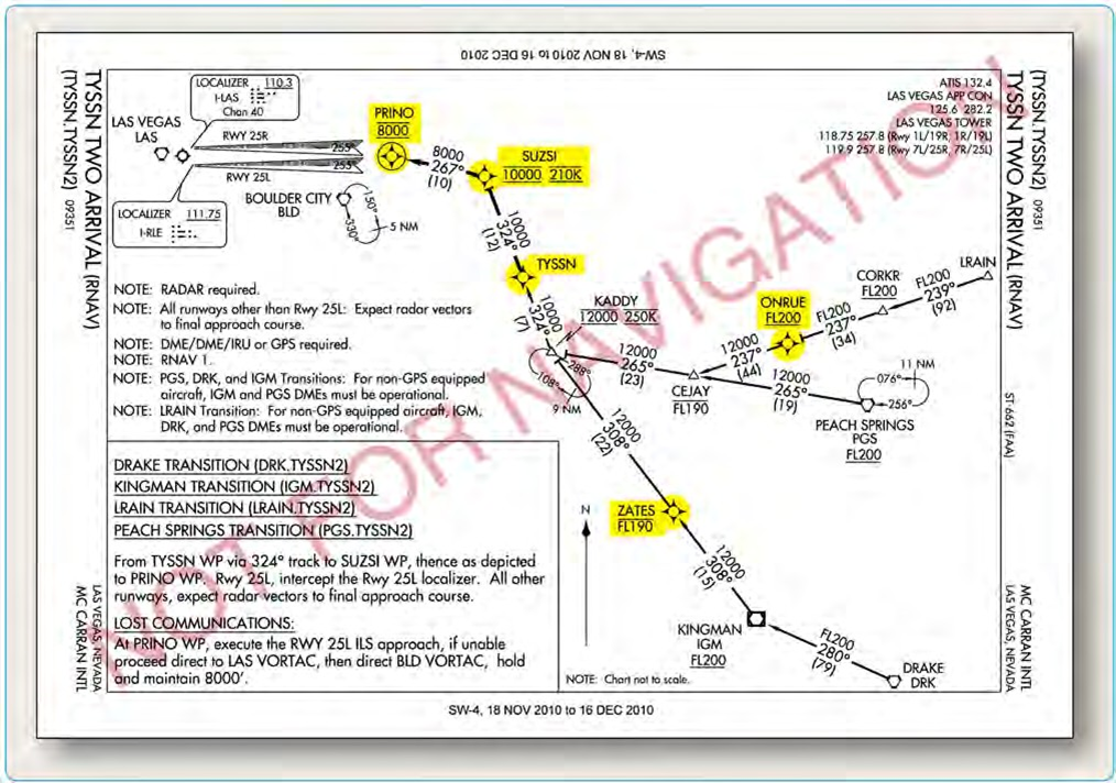
Figure 4-9. Fly-by and fly-over waypoints.
Approach waypoints, except for the missed approach waypoint (MAWP) and the missed approach holding waypoint (MAHWP), are normally FB WPs. Notice that in the plan view in Figure 4-9, there are four FB WPs, but only the circled WP symbol at PRINO is a FO WP. If flying manually to a selected RNAV WP, pilots should anticipate the turn at a FB WP to ensure a smooth transition and avoid overshooting the next flight segment. Alternatively, for a FO WP, no turn is accomplished until the aircraft passes the WP.
There are circumstances when a WP may be coded into the database as both a FB WP and a FO WP, depending on how the WPs are sequenced during the approach procedure. For example, a WP that serves as an IAF may be coded as a FB WP for the approach and as a FO WP when it also serves as the MAWP for the missed approach procedure (MAP). This is just one reason why instrument approaches should be loaded in their entirety from the FMS and not manually built or modified.
Altitudes
Prescribed altitudes may be depicted in four different configurations: minimum, maximum, recommended, and mandatory. The U.S. Government distributes approach charts produced by the FAA. Altitudes are depicted on these charts in the profile view with an underscore or overscore, or both to identify them as minimum, maximum, or mandatory, respectively.
- Minimumaltitudesaredepictedwiththealtitudevalue underscored. Aircraft are required to maintain altitude at or above the depicted value (e.g., 3000).
- Maximumaltitudesaredepictedwiththealtitudevalue overscored. Aircraft are required to maintain altitude at or below the depicted value (e.g., 4800).
- Mandatoryaltitudesaredepictedwiththealtitudevalue both underscored and overscored. Aircraft are required to maintain altitude at the depicted value (e.g., 5500).
- Recommended altitudes are depicted without an underscore or overscore.
Note: Pilots are cautioned to adhere to altitudes as prescribed because, in certain instances, they may be used as the basis for vertical separation of aircraft by ATC. If a depicted altitude is specified in the ATC clearance, that altitude becomes mandatory as defined above.
Minimum Safe/Sector Altitude
Minimum Safe Altitudes are published for emergency use on IAP charts. MSAs provide 1,000 feet of clearance over all obstacles but do not necessarily assure acceptable navigation signal coverage. The MSA depiction on the plan view of an approach chart contains the identifier of the center point of the MSA, the applicable radius of the MSA, a depiction of the sector(s), and the minimum altitudes above mean sea level which provide obstacle clearance. For conventional navigation systems, the MSA is normally based on the primary omnidirectional facility on which the IAP is predicated, but may be based on the airport reference point (ARP) if no suitable facility is available. For RNAV approaches, the MSA is based on an RNAV waypoint. MSAs normally have a 25 NM radius; however, for conventional navigation systems, this radius may be expanded to 30 NM if necessary to encompass the airport landing surfaces.
Depicted on the Plan View of approach charts, a single sector altitude is normally established. However when it is necessary to obtain obstacle clearance, an MSA area may be further divided with up to four sectors.
Final Approach Fix Altitude
Another important altitude that should be briefed during an IAP briefing is the FAF altitude, designated by the cross on a non-precision approach, and the lightning bolt symbol designating the glideslope/glidepath intercept altitude on a precision approach. Adherence and cross-check of this altitude can have a direct effect on the success and safety of an approach.
Proper airspeed, altitude, and configuration, when crossing the FAF of a non-precision approach, are extremely important no matter what type of aircraft is being flown. The stabilized approach concept, implemented by the FAA within the SOPs of each air carrier, suggests that crossing the FAF at the published altitude is often a critical component of a successful non-precision approach, especially in a large turbojet aircraft.
The glideslope intercept altitude of a precision approach should also be included in the IAP briefing. Awareness of this altitude when intercepting the glideslope can ensure the flight crew that a “false glideslope” or other erroneous indication is not inadvertently followed. Many air carriers include a standard callout when the aircraft passes over the FAF of the non-precision approach underlying the ILS. The PM states the name of the fix and the charted glideslope altitude, thus allowing both pilots to cross-check their respective altimeters and verify the correct indications.
Minimum Descent Altitude (MDA), Decision Altitude (DA), And Decision Height (DH)
MDA—the lowest altitude, expressed in feet MSL, to which descent is authorized on final approach or during circle-to• land maneuvering in execution of a standard instrument approach procedure (SIAP) where no electronic glideslope is provided.
DA—a specified altitude in the precision approach at which a missed approach must be initiated if the required visual reference to continue the approach has not been established.
DH—with respect to the operation of aircraft, means the height at which a decision must be made during an ILS, MLS, or PAR IAP to either continue the approach or to execute a missed approach.
CAT II and III approach DHs are referenced to AGL and measured with a radio altimeter.
The height above touchdown (HAT) for a CAT I precision approach is normally 200 feet above touchdown zone elevation (TDZE). When a HAT of 250 feet or higher is published, it may be the result of the signal-in-space coverage, or there may be penetrations of either the final or missed approach obstacle clearance surfaces (OCSs). If there are OCS penetrations, the pilot has no indication on the approach chart where the obstacles are located. It is important for pilots to brief the MDA, DA, or DH so that there is no ambiguity as to what minimums are being used. These altitudes can be restricted by many factors. Approach category, inoperative equipment in the aircraft or on the ground, crew qualifications, and company authorizations are all examples of issues that may limit or change the height of a published MDA, DA, or DH.
For many air carriers, OpSpecs may be the limiting factor for some types of approaches. NDB and circling approaches are two common examples where the OpSpecs minimum listed altitudes may be more restrictive than the published minimums. Many Part 121 and 135 operators are restricted from conducting circling approaches below 1,000 feet MDA and 3 SM visibility by Part C of their OpSpecs, and many have specific visibility criteria listed for NDB approaches that exceed visibilities published for the approach (commonly 2 SM). In these cases, flight crews must determine which is the more restrictive of the two and comply with those minimums.
In some cases, flight crew qualifications can be the limiting factor for the MDA, DA, or DH for an instrument approach. There are many CAT II and III approach procedures authorized at airports throughout the United States, but RNP AR restricts their use to pilots who have received specific training, and aircraft that are equipped and authorized to conduct those approaches. Other rules pertaining to flight crew qualifications can also determine the lowest usable MDA, DA, or DH for a specific approach. 14 CFR Part 121, § 121.652, 14 CFR Part 125, § 125.379, and 14 CFR Part 135, § 135.225 require that some PICs, with limited experience in the aircraft they are operating, increase the approach minimums and visibility by 100 feet and one-half mile respectively. Rules for these “high• minimums” pilots are usually derived from a combination of federal regulations and the company’s OpSpecs. There are many factors that can determine the actual minimums that can be used for a specific approach. All of them must be considered by pilots during the preflight and approach planning phases, discussed, and briefed appropriately.
Pilots are cautioned to fully understand and abide by the guidelines set forth in 14 CFR § 91.175(c) regarding proper identification of the runway and runway environment when electing to continue any approach beyond the published DA/DH or MDA.
It is imperative to recognize that any delay in making a decision to execute the Missed Approach Procedure at the DA/DH or MDA/Missed Approach Point will put the aircrew at risk of impacting any obstructions that may be penetrating the visual obstacle clearance surface The visual segment of an IAP begins at DA or MDA and continues to the runway. There are two means of operating in the visual segment, one is by using natural vision under 14 CFR Part 91, § 91.175 (c) and the other is by using an Enhanced Flight Vision System under 14 CFR Part 91, § 91.176.
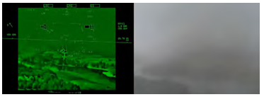
Figure 4-10A. View during an approach with EFVS (left) and without EFVS (right). (Images courtesy of NASA Langley Research Center)
Enhanced Flight Vision Systems (EFVS) and Instrument Approaches [Figure 4-10A]
An Enhanced Flight Vision System (EFVS) is an installed aircraft system which uses a head up display (HUD), or an equivalent display that is a head up presentation, to combine aircraft flight information and flight symbology, navigation guidance, and a real-time image of the external scene to the pilot on a single display. Imaging sensors, which may be based on forward-looking infrared (FLIR), millimeter wave radiometry, millimeter wave radar, low-level light intensification, or other real-time imaging technologies, produce a real-time image of the outside scene. Combining the flight information, navigation guidance, and sensor imagery on a HUD or equivalent display allows the pilot to continue looking forward along the flightpath throughout the entire approach, landing, and rollout.
Sections 91.175(c) and 91.176 specify two means of operating visually below DA/DH or MDA in the visual segment of an IAP. One means is by using natural vision under § 91.175(c), and the other is by using enhanced vision provided by an EFVS under § 91.176. When the runway environment cannot be visually acquired using natural vision, a pilot may use an EFVS to continue descending below DA/DH or MDA under §
91.176. An EFVS operation is an operation in which visibility conditions require an EFVS to be used in lieu of natural vision to perform an approach or landing, determine enhanced flight visibility, identify required visual references, or conduct a rollout. There are two types of EFVS operations – EFVS operations to touchdown and rollout and EFVS operations to 100 feet above the touchdown zone elevation (TDZE). An EFVS operation to touchdown and rollout is an operation in which a pilot uses the enhanced vision imagery provided by an EFVS in lieu of natural vision to descend below DA or DH to touchdown and rollout [Figure 4-10B]. These operations may be conducted on standard instrument approach procedures (SIAPs) or special instrument approach procedures (IAPs) that have a DA or DH (e.g., Precision or APV approach).
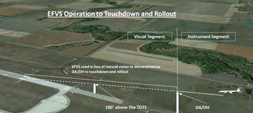
Figure 4-10B. EFVS Operation to Touchdown and Rollout.
An EFVS operation to 100 feet above the TDZE is an operation in which the pilot uses the EFVS in lieu of natural vision to descend below DA/DH or MDA down to 100 feet above the TDZE [Figure 4-10C]. To descend below 100 feet above the TDZE, however, natural vision must be used. EFVS operations to 100 feet above the TDZE may be conducted on SIAPs or special IAPs that have a DA/DH or MDA. While the regulations do not prohibit EFVS from being used during any phase of flight for situational awareness, EFVS displays are not designed, installed, certified, or intended as a sufficient visual system to conduct circling maneuvers. EFVS may only be used during a circle-to-land maneuver provided the visual references required throughout the circling maneuver are distinctly visible to the pilot using natural vision throughout the circling maneuver. Therefore, an EFVS cannot be used to satisfy the requirement that an identifiable part of the airport be distinctly visible to the pilot during a circling maneuver at or above MDA or while descending below MDA from a circling maneuver.
The visual information provided by an EFVS serves as independent verification of the position information provided by the aircraft’s displays and systems. An EFVS also enables a pilot to assess the enhanced flight visibility and identify required visual references, helps a pilot align the aircraft with the runway, and provides position, roll, rate of closure, and distance remaining information. Sections 91.176(a) and 91.176(b) permit a pilot to use an EFVS to identify the required visual references and to determine that the enhanced flight visibility provided by the EFVS is not less than the visibility prescribed in the IAP to be flown. Both the visual reference and enhanced flight visibility requirements of the regulations must be met before the pilot can descend below DA/DH during an EFVS operation to touchdown and rollout or below DA/DH or MDA during an EFVS operation to 100 feet above the TDZE. The aircraft also must continuously be in a position from which a descent to landing can be made on the intended runway at a normal rate of descent using normal maneuvers. For EFVS operations to touchdown, § 91.176(a)(2)(vi) requires that the descent rate must allow touchdown to occur within the touchdown zone of the runway of intended landing for all operations. Section 91.176(b)(2)(v), operations conducted to 100 feet above the TDZE, requires the descent rate to allow touchdown to occur within the touchdown zone of the runway of intended landing for operations conducted under 14 CFR Parts 121 and 135.
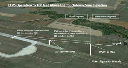
Figure 4-10C. EFVS Operations to 100 Feet Above the TDZE.
It is important to understand that using an EFVS does not result in obtaining lower minima with respect to the visibility or the DA/DH or MDA specified in the IAP. For example, a pilot who is using an EFVS on a Category I ILS approach that specifies a DA of 200 feet and a required visibility of RVR 2400 feet must comply with a 200-foot DA and an enhanced flight visibility of 2400 feet, even though the pilot may not have 2400 feet of flight visibility using natural vision or a reported visibility of RVR 2400 feet. The decision altitude is specified by the IAP the pilot is flying, and it does not change whether EFVS is used or not. Accordingly, the visibility specified in the IAP does not change. The difference is whether the pilot assesses the RVR 2400 feet visibility prescribed by the IAP using natural vision or whether he or she assesses it using an EFVS. An EFVS simply provides another means of operating in the visual segment of an IAP. That is, it gives the pilot another means to see the required visual references when they might not be visible using natural vision, and it gives the pilot a means to see forward along the flightpath the distance required by the enhanced flight visibility – when he or she might not be able to do so using natural vision.
During an EFVS operation, a pilot must initiate a go-around at or below DA/DH or MDA whenever the requirements of § 91.176 are not met. The published missed approach procedure provides obstacle clearance only when the missed approach is initiated from or above the DA/DH, or at the MAP. It assumes a climb rate of 200 fT/NM unless a higher climb gradient is identified on the procedure. If a pilot initiates a go-around at a point below DA/DH or after the MAP, obstacle clearance is not necessarily provided by following the published missed approach procedure. Prior planning is recommended and should include contingencies between the published MAP and touchdown with reference to obstacle clearance, aircraft performance, and alternate escape plans. Additionally, pilots should be especially knowledgeable of the approach conditions and approach course alignment when considering whether to rely on EFVS during an instrument approach with an offset final approach course. Depending upon the combination of crosswind correction, approach course offset, and the lateral field of view provided by a particular EFVS, the required visual references may or may not be within the pilot’s view looking through the EFVS upon reaching the MAP. AC 90-106 (current version) contains additional information about visual segment obstacle clearance, missed approach obstacle clearance, and considerations associated with offset approaches.
Operators that have a specific approval from the FAA to conduct special IAPs should evaluate those instrument procedures to determine their compatibility with EFVS operations. Special IAPs are frequently dependent on the ability of the operator to meet certain requirements that may include aircraft performance, equipage, airport facility equipment, crew training, or other requirements. These procedures also may have nonstandard features such as nonstandard final approach course alignment, nonstandard descent gradients, or other features that may or may not be compatible with the conduct of EFVS operations.
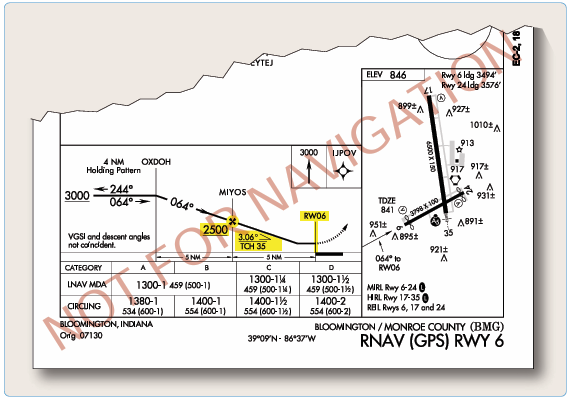
Figure 4-11A. VNAV information
Under § 91.176(a), operators who have been issued OpSpec C073, MSpec MC073, or LOA C073, may conduct EFVS operations to touchdown and rollout on certain vertical navigation (VNAV) IAPs that use an MDA as a DA/DH in accordance with C073. Additionally, §§ 91.176 and 91.189 permit an authorized EFVS operation to be conducted during an authorized Category II or Category III operation.
Currently, EFVS operations in rotorcraft can be conducted only on IAPs that are flown to a runway. Instrument approach criteria, procedures, and appropriate visual references have not yet been developed for straight-in landing operations below DA/DH or MDA under IFR to heliports or platforms. EFVS cannot be used in lieu of natural vision to descend below published minimums on copter approaches to a point-in-space (PinS) followed by a “proceed visual flight rules (VFR)” visual segment, or on approaches designed to a specific landing site using a “proceed visually” visual segment.
Vertical Navigation
One of the advantages of some GPS and multi-sensor FMS RNAV avionics is the advisory VNAV capability. Traditionally, the only way to get vertical path information during an approach was to use a ground-based precision NAVAID. Modern RNAV avionics can display an electronic vertical path that provides a constant-rate descent to minimums.
Since these systems are advisory and not primary guidance, the pilot must continuously ensure the aircraft remains at or above any published altitude constraint, including step• down fix altitudes, using the primary barometric altimeter. The pilots, aircraft, and operator must be approved to use advisory VNAV inside the FAF on an instrument approach.
VNAV information appears on selected conventional nonprecision, GPS, and RNAV approaches (see “Types of Approaches” later in this chapter). It normally consists of two fixes (the FAF and the landing runway threshold), a FAF crossing altitude, a vertical descent angle (VDA), and may provide a visual descent point (VDP) [Figure 4-11A].
The VDA provides the pilot with advisory information not previously available on nonprecision approaches. It provides a means for the pilot to establish a stabilized descent from the FAF or step-down fix to the MDA. Stabilized descent is a key factor in the reduction of controlled flight into terrain (CFIT) incidents. However, pilots should be aware that the published angle is for information only − it is strictly advisory in nature. There is no implicit additional obstacle protection below the MDA. Pilots must still respect any published stepdown fixes and the published MDA unless the visual cues stated 14 CFR
§ 91.175 are present, and they can visually acquire and avoid both lit and unlit obstacles once below the MDA. The presence of a VDA does not guarantee obstacle protection in the visual segment and does not change any of the requirements for flying a nonprecision approach.
Pilots may use the published angle and estimated/actual groundspeed to find a target rate of descent from the rate of descent table published in the back of the U.S. Terminal Procedures Publication. This rate of descent can be flown with the Vertical Velocity Indicator (VVI) in order to use the VDA as an aid to flying a stabilized descent. No special equipment is required.
In rare cases, the LNAV minima may have a lower HAT than minima with a glide path, due to the location of the obstacles and the nonprecision MAP. This should serve as a clear indication to the pilot that obstacles exist below the MDA, which must be seen in order to ensure adequate clearance. In those cases, the glide path may be treated as a VDA and used to descend to the LNAV MDA, as long as all of the rules for a nonprecision approach are applied at the MDA. When there are obstacles in the visual area that could cause an aircraft to destabilize the approach between the MDA and touchdown, the IAP will not show a vertical descent angle in the profile view. The charts currently include the following statement: “Descent Angle NA” or “Descent Angle NA-Obstacles” [Figure 4-11B ].
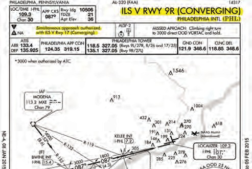
Figure 4-11B. Descent Angle N/A..
Figure 4-12. RNAV GPS approach minima.
Like flying any other IAP, the pilot must see and avoid any obstacles in the visual segment during transition to landing. A constant-rate descent has many safety advantages over non-precision approaches that require multiple level-offs at stepdown fixes or manually calculating rates of descent. A stabilized approach can be maintained from the FAF to the landing when a constant-rate descent is used. Additionally, the use of an electronic vertical path produced by onboard avionics can serve to reduce CFIT, and minimize the effects of visual illusions on approach and landing. Some countries even mandate the use of continuous descent final approaches (CDFAs) on non-precision approaches.
Wide Area Augmentation System
The Wide Area Augmentation System (WAAS) offers an opportunity for airports to gain ILS like approach capability without the purchase or installation of any ground-based navigation equipment at the airport.
Today, WAAS is already being used at more than 900 runways across the United States to achieve minimums as low as 200 feet height above HAT/one-half mile visibility.
Benefits Of WAAS In The Airport Environment
WAAS is a navigation service using a combination of GPS satellites and the WAAS geostationary satellites to improve the navigational service provided by GPS. WAAS achieved initial operating capability (IOC) in 2003. The system is owned and operated by the FAA and provided free of direct user charges to users across the United States and most of Canada and Mexico.
WAAS improves the navigational system accuracy for en route, terminal, and approach operations over all the continental United States and significant portions of Alaska, Canada, and Mexico. This new navigational technology supports vertically-guided instrument approaches to all qualifying runways in the United States. Vertically-guided approaches reduce pilot workload and provide safety benefits compared to non-precision approaches. The WAAS enabled vertically guided approach procedures are called LPV, which stands for “localizer performance with vertical guidance,”and provide ILS equivalent approach minimums as low as 200 feet at qualifying airports. Actual minimums are based on an airport’s current infrastructure, as well as an evaluation of any existing obstructions. The FAA plans to publish 300 WAAS approach procedures per year to provide service to all qualifying instrument runways within the NAS.
Advantages Of WAAS Enabled LPV Approaches
The advantages of WAAS enabled LPV approaches include:
- No consideration needs to be given to the placement of navigation facility, maintenance of clear zones
- LPV procedures have no requirement for ground- based transmitters at the airport.
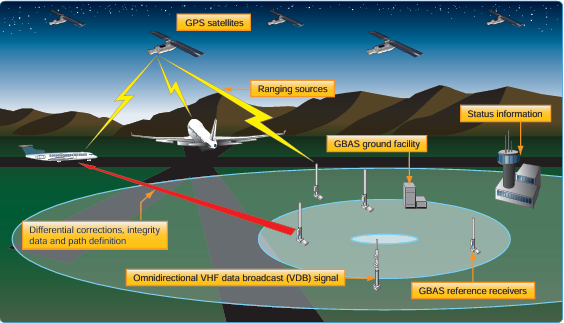
Figure 4-13. GBAS architecture.
around the facility, or access to the facility for maintenance.
- LPV approaches eliminate the need for critical area limitations associated with an ILS.
- From a pilot’s viewpoint, an LPV approach looks and flies like an ILS, but the WAAS approach is more stable than that of an ILS.
- WAAS equipped users can fly RNAV and basic required navigation performance (RNP) procedures, as well as LPV procedures, and the avionics costs are relatively inexpensive considering the total navigation solution provided.
RNAV (GPS) approach charts normally have four lines of approach minimums: LPV, LNAV/VNAV, LNAV, and Circling. Figure 4-12 shows how these minimums might be presented on an approach chart, with the exception of Ground Based Augmentation System (GBAS) Landing System (GLS). This enables as many GPS equipped aircraft to use the procedure as possible and provides operational flexibility if WAAS becomes unavailable. Some aircraft may only be equipped with GPS receivers so they can fly to the LNAV MDA. Some aircraft equipped with GPS and FMS (with approach-certified barometric vertical navigation, or Baro-VNAV) can fly to the LNAV/VNAV MDA. Flying a WAAS LPV approach requires an aircraft with WAAS-LPV avionics. If for some reason the WAAS service becomes unavailable, all GPS or WAAS equipped aircraft can revert to the LNAV MDA and land safely using GPS only, which is available nearly 100 percent of the time. Some locations will have an LP line of minima on an RNAV (GPS) approach chart; but the use of LP is being phased out. At locations with obstacle penetrations in the missed approach segment, there might be two lines of minima for the same type of navigation- one line with higher approach minima without a specified climb gradient and another line with lower approach minima with a specified climb gradient in the event of missed approach.
LPV identifies WAAS approach with vertical guidance (APV) approach minimums with electronic lateral and vertical guidance capability. LPV is used for approaches constructed with WAAS criteria where the value for the vertical alarm limit is more than 12 meters and less than 50 meters. WAAS avionics equipment approved for LPV approaches is required for this type of approach. The lateral guidance is equivalent to localizer accuracy, and the protected area is considerably smaller than the protected area for the present LNAV and LNAV/VNAV lateral protection. Aircraft can fly this minima line with a statement in the AFM that the installed equipment supports LPV approaches. In Figure 4-12, notice the WAAS information shown in the top left corner of the pilot briefing information on the chart depicted. Below the term WAAS is the WAAS channel number (CH 56202), and the WAAS approach identifier (W35A), indicating Runway 35L in this case, and then a letter to designate the first in a series of procedures to that runway [Figure 4-12].
LNAV/VNAV identifies APV minimums developed to accommodate an RNAV IAP with vertical guidance, usually provided by approach certified Baro-VNAV, but with vertical and lateral integrity limits larger than a precision approach or LPV. Many RNAV systems that have RNP 0.3 or less approach capability are specifically approved in the AFM. Airplanes that are commonly approved in these types of operations include Boeing 737NG, 767, and 777, as well as the Airbus A300 series. Landing minimums are shown as DAs because the approaches are flown using an electronic glide path. Other RNAV systems require special approval. In some cases, the visibility minimums for LNAV/VNAV might be greater than those for LNAV only. This situation occurs because DA on the LNAV/VNAV vertical descent path is farther away from the runway threshold than the LNAV MDA missed approach point.
Also shown in Figure 4-12, is the LNAV minimums line. This minimum is for lateral navigation only, and the approach minimum altitude is published as a MDA. LNAV provides the same level of service as the present GPS stand alone approaches. LNAV supports the following systems: WAAS, when the navigation solution will not support vertical navigation; and GPS navigation systems which are presently authorized to conduct GPS approaches.
Circling minimums that may be used with any type of approach approved RNAV equipment when publication of straight-in approach minimums is not possible.
Ground-Based Augmentation System (GBAS)
The United States version of the Ground-Based Augmentation System (GBAS) has traditionally been referred to as the Local Area Augmentation System (LAAS). The worldwide community has adopted GBAS as the official term for this type of navigation system. To coincide with international terminology, the FAA is also adopting the term GBAS to be consistent with the international community. GBAS is a ground-based augmentation to GPS that focuses its service on the airport area (approximately a 20–30 mile radius) for precision approach, DPs, and terminal area operations. It broadcasts its correction message via a very high frequency (VHF) radio data link from a ground-based transmitter. GBAS yields the extremely high accuracy, availability, and integrity necessary for Category I, II, and III precision approachesand provides the ability for flexible, curved approach paths. GBAS demonstrated accuracy is less than one meter in both the horizontal and vertical axis. [Figure 4-13]
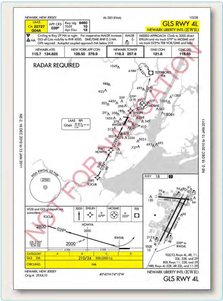
Figure 4-14. GLS approach at Newark, New Jersey.
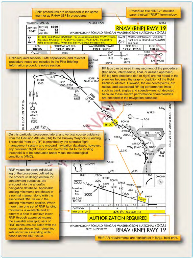
Figure 4-15. RNAV RNP approach procedure with curved flight tracks.
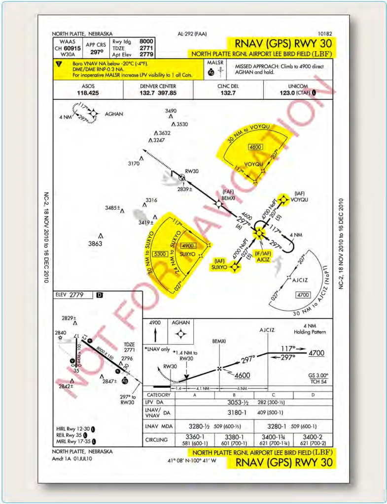
Figure 4-16. North Platte Regional (KLBF), North Platte, Nebraska, RNAV (GPS) RWY 30.
The GBAS augments the GPS to improve aircraft safety during airport approaches and landings. It is expected that the end state configuration will pinpoint the aircraft’s position to within one meter or less with a significant improvement in service flexibility and user operating costs.
GBAS is comprised of ground equipment and avionics. The ground equipment includes four reference receivers, a GBAS ground facility, and a VHF data broadcast transmitter. This ground equipment is complemented by GBAS avionics installed on the aircraft. Signals from GPS satellites are received by the GBAS GPS reference receivers (four receivers for each GBAS) at the GBAS equipped airport. The reference receivers calculate their position using GPS. The GPS reference receivers and GBAS ground facility work together to measure errors in GPS provided position.
The GBAS ground facility produces a GBAS correction message based on the difference between actual and GPS calculated position. Included in this message is suitable integrity parameters and approach path information. This GBAS correction message is then sent to a VHF data broadcast (VDB) transmitter. The VDB broadcasts the GBAS signal throughout the GBAS coverage area to avionics in GBAS equipped aircraft. GBAS provides its service to a local area (approximately a 20–30 mile radius). The signal coverage is designed support the aircraft’s transition from en route airspace into and throughout the terminal area airspace.
The GBAS equipment in the aircraft uses the corrections provided on position, velocity, and time to guide the aircraft safely to the runway. This signal provides ILS look alike guidance as low as 200 feet above touchdown. GBAS will eventually support landings all the way to the runway surface. Figure 4-14 is an example of a GBAS (LAAS) approach into Newark, New Jersey.
Required Navigation Performance (RNP)
The operational advantages of RNP include accuracy, onboard performance monitoring and alerting which provide increased navigation precision and lower minimums than conventional RNAV. RNP DAs can be as low as 250 feet with visibilities as low as 3/4 SM. Besides lower minimums, the benefits of RNP include improved obstacle clearance limits, as well as reduced pilot workload. When RNP capable aircraft fly an accurate, repeatable path, ATC can be confident that these aircraft are at a specific position, thus maximizing safety and increasing capacity.
To attain the benefits of RNP approach procedures, a key component is curved flight tracks. Constant radius turns around a fix are called “radius-to-fix legs (RF legs).” These turns, which are encoded into the navigation database, allow the aircraft to avoid critical areas of terrain or conflicting airspace while preserving positional accuracy by maintaining precise, positive course guidance along the curved track. The introduction of RF legs into the design of terminal RNAV procedures results in improved use of airspace and allows procedures to be developed to and from runways that are otherwise limited to traditional linear flight paths or, in some cases, not served by an IFR procedure at all. Navigation systems with RF capability are a prerequisite to flying a procedure that includes an RF leg. Refer to the notes box of the pilot briefing portion of the approach chart in Figure 4-15.
In the United States, operators who seek to take advantage of RNP approach procedures must meet the special RNP requirements outlined in FAA AC 90-101, Approval Guidance for RNP Procedures with Authorization Required (AR). Currently, most new transport category airplanes receive an airworthiness approval for RNP operations. However, differences can exist in the level of precision that each system is qualified to meet. Each individual operator is responsible for obtaining the necessary approval and authorization to use these instrument flight procedures with navigation databases.
RNAV Approach Authorization
Like any other authorization given to air carriers and Part 91 operators, the authorization to use VNAV on a conventional non-precision approach, RNAV approaches, or LNAV/VNAV approaches is found in that operator’s OpSpecs, AFM, or other FAA-approved documents. There are many different levels of authorizations when it comes to the use of RNAV approach systems. The type of equipment installed in the aircraft, the redundancy of that equipment, its operational status, the level of flight crew training, and the level of the operator’s FAA authorization are all factors that can affect a pilot’s ability to use VNAV information on an approach.
Because most Part 121, 125, 135, and 91 flight departments include RNAV approach information in their pilot training programs, a flight crew considering an approach to North Platte, Nebraska, using the RNAV (GPS) RWY 30 approach shown in Figure 4-16, would already know which minimums they were authorized to use. The company’s OpSpecs, FOM, and the AFM for the pilot’s aircraft would dictate the specific operational conditions and procedures by which this type of approach could be flown. There are several items of note that are specific to this type of approach that should be considered and briefed. One is the terminal arrival area (TAA) that is displayed in the approach planview. TAAs, discussed later in this chapter, depict the boundaries of specific arrival areas, and the MIA for those areas. The TAAs should be included in an IAP briefing in the same manner as any other IFR transition altitude. It is also important to note that the altitudes listed in the TAAs should be referenced in place of the MSAs on the approach chart for use in emergency situations.
In addition to the obvious differences contained in the planview of Figure 4-16, RNAV (GPS) approach procedure example, pilots should be aware of the issues related to Baro-VNAV and RNP . The notes section of the procedure in the example contains restrictions relating to these topics.
RNP values for each individual leg of the procedure, defined by the procedure design criteria for containment purposes, are encoded into the aircraft’s navigation database. Applicable landing minimums are shown in a normal manner along with the associated RNP value in the landing minimums section.
RNP required sensors, FMS capabilities, and relevant procedure notes are included in the Pilot Briefing Information procedure notes section. [Figure 4-15] RNP AR requirements are highlighted in large, bold print. RNP procedures are sequenced in the same manner as RNAV (GPS) procedures. Procedure title “RNAV” includes parenthetical “(RNP)” terminology. RF legs can be used in any segment of the procedure (transition, intermediate, final, or missed approach). RF leg turn directions (left or right) are not noted in the planview because the graphic depiction of the flight tracks is intuitive. Likewise, the arc center points, arc radius, and associated RF leg performance limits, such as bank angles and speeds are not depicted because these aircraft performance characteristics are encoded in the navigation database. RNP values for each individual leg of the procedure, defined by the procedure design criteria for containment purposes, are encoded into the aircraft’s navigation database. Applicable landing minimums are shown in a normal manner along with the associated RNP value in the landing minimums section.
When more than one set of RNP landing minimums is available and an aircrew is able to achieve lower RNP through approved means, the available (multiple) sets of RNP minimums are listed with the lowest set shown first; remaining sets shown in ascending order, based on the RNP value. On this particular procedure, lateral and vertical course guidance from the DA to the Runway Waypoint (LTP) is provided by the aircraft’s FMS and onboard navigation database; however, any continued flight below the DA to the landing threshold is to be conducted under VMC. [Figure 4-15]
Baro-VNAV
Baro-VNAV is an RNAV system function that uses barometric altitude information from the aircraft’s altimeter to compute and present a vertical guidance path to the pilot. The specified vertical path is computed as a geometric path, typically computed between two waypoints or an angle based computation from a single waypoint. Operational approval must also be obtained for Baro− VNAV systems to operate to the LNAV/VNAV minimums. Baro−VNAV may not be authorized on some approaches due to other factors, such as no local altimeter source being available. Baro−VNAV is not authorized on LPV procedures.
For the RNAV (GPS) RWY 30 approach, the note “DME/ DME RNP-0.3 NA” prohibits aircraft that use only DME/ DME sensors for RNAV from conducting the approach. [Figure 4-16]
Because these procedures can be flown with an approach approved RNP system and “RNP” is not sensor specific, it was necessary to add this note to make it clear that those aircraft deriving RNP 0.3 using DME/DME only are not authorized to conduct the procedure.
The least accurate sensor authorized for RNP navigation
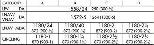
Figure 4-17. Example of LNAV and Circling Minima lower than LNAV/VNAV DA. Harrisburg International RNAV (GPS) Runway 13.

Figure 4-18. Explanation of Minima.
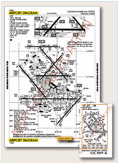
Figure 4-19. Airport sketch and diagram for Chicago O’Hare International.
is DME/DME. The necessary DME NAVAID ground infrastructure may or may not be available at the airport of intended landing. The procedure designer has a computer program for determining the usability of DME based on geometry and coverage. Where FAA flight inspection successfully determines that the coverage and accuracy of DME facilities support RNP, and that the DME signal meets inspection tolerances, although there are none currently published, the note “DME/DME RNP 0.3 Authorized” would be charted. Where DME facility availability is a factor, the note would read,“DME/DME RNP 0.3 Authorized; ABC and XYZ required,”meaning that ABC and XYZ DME facilities are required to assure RNP 0.3.
Hot and Cold Temperature Limitations
A minimum and maximum temperature limitation is published on procedures that authorize Baro−VNAV operation. These temperatures represent the airport temperature above or below which Baro−VNAV is not authorized to LNAV/VNAV minimums unless temperature compensation can be accomplished. As an example, the limitation will read, uncompensated Baro−VNAV NA below −11 °C (12 °F) or above 49 °C (120 °F). [Figure 4-15] This information will be found in the upper left hand box of the pilot briefing. When the temperature is above the high temperature or below the low temperature limit, Baro−VNAV may be used to provide a stabilized descent to the LNAV MDA; however, extra caution should be used in the visual segment to ensure a vertical correction is not required. If the VGSI is aligned with the published glide path, and the aircraft instruments indicate on glide path, an above or below glide path indication on the VGSI may indicate that temperature error is causing deviations to the glide path. These deviations should be considered if the approach is continued below the MDA.
Many systems which apply Baro−VNAV temperature compensation only correct for cold temperature. In this case, the high temperature limitation still applies. Also, temperature compensation may require activation by maintenance personnel during installation in order to be functional, even though the system has the feature. Some systems may have a temperature correction capability, but correct the Baro−altimeter all the time, rather than just on the final, which would create conflicts with other aircraft if the feature were activated. Pilots should be aware of compensation capabilities of the system prior to disregarding the temperature limitations. The information can be seen in the notes section in Figure 4-16.
In response to aviation industry concerns over cold weather altimetry errors, the FAA conducted a risk analysis to determine if current 14 CFR Part 97 instrument approach procedures, in the NAS place aircraft at risk during cold temperature operations. This study applied the coldest recorded temperature at the given airports in the last five years and specifically determined if there was a probability that during these non-standard day operations, anticipated altitude errors in a barometric altimetry system could exceed the Required Obstacle Clearance (ROC) used on procedure segment altitudes. If a probability of the ROC being exceeded went above one percent on a segment of the approach, a temperature restriction was applied to that segment. In addition to the low probability that these procedures will be required, the probability of the ROC being exceeded precisely at an obstacle position is extremely low, providing an even greater safety margin.
Pilots need to make an altitude correction to the published, “at”, “at or above” and“at or below” altitudes on designated segment(s) of IAPs listed at specific airports, on all published procedures and runways, when the reported airport temperature is at or below the published airport cold temperature restriction.
This list may also be found at the bottom of the, “Terminal Procedures Basic Search” page found at: http://www.faa. gov/air_traffic/flight_info/aeronav/digital_products/dtpp/ search/
Pilots without temperature compensating aircraft are responsible to calculate and make a manual cold- temperature altitude correction to the designated segment(s) of the approach using the AIM 7-2-3, ICAO Cold Temperature Error Table.
No extrapolation above the 5000 ft column required. Pilots should use the 5000 feet “height above airport in feet” column for calculating corrections of greater than 5000 feet above reporting station. Pilots will add correction(s) from the table to the segment altitude(s) and fly at the new corrected altitude. PILOTS SHOULD NOT MAKE AN ALTIMETER CHANGE to accomplish an altitude correction.
Pilots with temperature compensating aircraft must ensure the system is on and operating for each segment requiring an altitude correction. Pilots must ensure they are flying at corrected altitude. If the system is not operating, the pilot is responsible to calculate and apply a manual cold weather altitude correction using the AIM 7-2-3 ICAO Cold Temperature Error Table.
Pilots must report cold temperature corrected altitudes to Air Traffic Control (ATC) whenever applying a cold temperature correction on an intermediate segment and/ or a published missed approach final altitude. This should be done on initial radio contact with the ATC issuing approach clearance. ATC requires this information in order to ensure appropriate vertical separation between known traffic. ATC will not beproviding a cold temperature correction to Minimum Vectoring Altitudes (MVA). Pilots must not apply cold temperature compensation to ATC assigned altitudes or when flying on radar vectors in lieu of a published missed approach procedure unless cleared by ATC.
Pilots should query ATC when vectors to an intermediate segment are lower than the requested intermediate segment altitude corrected for temperature. Pilots are encouraged to self-announce corrected altitude when flying into uncontrolled airfields.
The following are examples of appropriate pilot-to-ATC communication when applying cold-temperature altitude corrections:
On initial check-in with ATC providing approach clearance: Hayden, CO (example below).
Intermediate segment: “Require 10600 ft. for cold temperature operations until BEEAR”,
Missed Approach segment: “Require final holding altitude, 10600 ft. on missed approach for cold temperature operations”
Pilots cleared by ATC for an instrument approach procedure;“Cleared the RNAV RWY 28 approach (from any IAF)”. Hayden, CO (example below).
Intermediate Segment:“Level 10600 ft for cold temperature operations inside HIPNA to BEEAR”
Pilots are not required to advise ATC if correcting on the final segment only. Pilots must use the corrected MDA or DA/DH as the minimum for an approach. Pilots must meet the requirements in 14 CFR Part 91.175 in order to operate below the corrected MDA or DA/DH. Pilots must see and avoid obstacles when descending below the MDA.
The temperature restriction at a “Cold Temperature Restricted Airport” is mutually exclusive from the charted temperature restriction published for “uncompensated baro-VNAV systems” on 14 CFR Part 97 RNAV (GPS) and RNAV (RNP) approach charts. The charted temperature restriction for uncompensated baro-VNAV systems is applicable to the final segment LNAV/VNAV minima. The charted temperature restriction must be followed regardless of the cold temperature restricted airport temperature.
Pilots are not required to calculate a cold temperature altitude correction at any airport with a runway length of 2,500 feet or greater that is not included in the airports list found at the URL above. Pilots operating into an airport with a runway length less than 2,500 feet, may make a cold temperature altitude correction in cold temperature conditions.
Cold Temperature Restricted Airports: These airports are listed in the FAA Notices To Airmen Publication (NTAP) found here: https://www.faa.gov/air_traffic/publications/ notices/.
Airports are listed by ICAO code, Airport Name, Temperature Restriction in Celsius/Fahrenheit and affected Segment. One temperature may apply to multiple segments. Italicized airports have two affected segments, each with a different temperature restrictions. The warmest temperature will be indicated on Airport IAPs next to a snowflake symbol, in the United States Terminal Procedure Publication. The ICON will be added to the TPPs incrementally each charting cycle.
LNAV, LNAV/VNAV and Circling Minimums
There are some RNAV procedures with lower non-precision LNAV minimums [Figure 4-17] than vertically-guided LNAV/VNAV minimums. Circling procedures found on the same approach chart may also have lower minimums than the vertically-guided LNAV/VNAV procedure. Each RNAV procedure is evaluated independently and different approach segments have differing required obstacle clearance (ROC) values, obstacle evaluation area (OEA) dimensions and final segment types. Figure 4-18 explains the differences.
Airport/Runway Information
Another important piece of a thorough approach briefing is the discussion of the airport and runway environment. A detailed examination of the runway length (this must include the A/FD section of the CS for the landing distance available), the intended turnoff taxiway, and the route of taxi to the parking area, are all important briefing items. In addition, runway conditions should be discussed. The effect on the aircraft’s performance must be considered if the runway is contaminated.
FAA approach charts include a runway sketch on each approach chart to make important airport information easily accessible to pilots. In addition, at airports that have complex runway/taxiway configurations, a separate full- page airport diagram is published.
The airport diagram also includes the latitude/longitude information required for initial programming of FMS equipment. The included latitude/longitude grid shows the specific location of each parking area on the airport surface for use in initializing FMS. Figure 4-19 shows the airport sketch and diagram for Chicago-O’Hare International Airport (KORD).
Pilots making approaches to airports that have this type of complex runway and taxiway configuration must ensure that they are familiar with the airport diagram prior to initiating an instrument approach. A combination of poor weather, high traffic volume, and high ground controller workload makes the pilot’s job on the ground every bit as critical as the one just performed in the air.
Instrument Approach Procedure (IAP) Briefing
A thorough instrument approach briefing greatly increases the likelihood of a successful instrument approach. Most Part 121, 125, and 135 operators designate specific items to be included in an IAP briefing, as well as the order in which those items are briefed.
Before an IAP briefing can begin, flight crews must decide which procedure is most likely to be flown from the information that is available to them. Most often, when the flight is being conducted into an airport that has ATIS information, the ATIS provides the pilots with the approaches that are in use. If more than one approach is in use, the flight crew may have to make an educated guess as to which approach will be issued to them based on the weather, direction of their arrival into the area, any published airport NOTAMs, and previous contact with the approach control facility. Aircrews can query ATC as to which approach is to be expected from the controller. Pilots may request specific approaches to meet the individual needs of their equipment or regulatory restrictions at any time and ATC will, in most cases, be able to accommodate those requests, providing that workload and traffic permit.
If the flight is operating into an airport without a control tower, the flight crew is occasionally given the choice of any available instrument approach at the field. In these cases, the flight crew must choose an appropriate approach based on the expected weather, aircraft performance, direction of arrival, airport NOTAMs, and previous experience at the airport.
Navigation and Communication Radios
Once the anticipated approach and runway have been selected, each crewmember sets up their side of the flight deck. The pilots use information gathered from ATIS, dispatch (if available), ATC, the specific approach chart for the approach selected, and any other sources that are available. Company regulations dictate how certain things are set up and others are left up to pilot technique. In general, the techniques used at most companies are similar. This section addresses two-pilot operations. During single-pilot IFR flights, the same items must be set up and the pilot should still do an approach briefing to verify that everything is set up correctly.
The number of items that can be set up ahead of time depends on the level of automation of the aircraft and the avionics available. In a conventional flight deck, the only things that can be set up, in general, are the airspeed bugs (based on performance calculations), altimeter bug (to DA, DH, or MDA), go around thrust/power setting, the radio altimeter bug (if installed and needed for the approach), and the navigation/communication radios (if a standby frequency selector is available). The standby side of the PF navigation radio should be set to the primary NAVAID for the approach and the PM navigation radio standby selector should be set to any other NAVAIDs that are required or available, and as dictated by company procedures, to add to the overall situational awareness of the crew. The ADF should also be tuned to an appropriate frequency as required by the approach, or as selected by the crew. Aircrews should, as much as possible, set up the instruments for best success in the event of a vacuum or electrical failure. For example, if the aircraft will only display Nav 1 on battery or emergency power, aircrews should ensure that Nav 1 is configured to the primary NAVAID for the final approach to be flown.
Flight Management System (FMS)
In addition to the items that are available on a conventional flight deck aircraft, glass flight deck aircraft, as well as aircraft with an approved RNAV (GPS) system, usually give the crew the ability to set the final approach course for the approach selected and many other options to increase situational awareness. Crews of FMS equipped aircraft have many options available as far as setting up the flight management computer (FMC), depending on the type of approach and company procedures. The PF usually programs the FMC for the approach and the PM verifies the information. A menu of available approaches is usually available to select from based on the destination airport programmed at the beginning of the flight or a new destination selected while en route.
The amount of information provided for the approach varies from aircraft to aircraft, but the crew can make modifications if something is not pre-programmed into the computer, such as adding a MAP or even building an entire approach for situational awareness purposes only. The PF can also program a VNAV profile for the descent and LNAV for segments that were not programmed during preflight, such as a standard terminal arrival route (STAR) or expected route to the planned approach. Any crossing restrictions for the STAR might need to be programmed as well. The most common crossing restrictions, whether mandatory or“to be expected,”are usually automatically programmed when the STAR is selected, but can be changed by ATC at any time. Other items that need to be set up are dictated by aircraft-specific procedures, such as autopilot, auto- throttles, auto-brakes, pressurization system, fuel system, seat belt signs, anti-icing/ deicing equipment, and igniters.
Autopilot Modes
In general, an autopilot can be used to fly approaches even if the FMC is inoperative (refer to the specific aircraft’s minimum equipment list (MEL) to determine authorization for operating with the FMC inoperative). Whether or not the FMC is available, use of the autopilot should be discussed during the approach briefing, especially regarding the use of the altitude pre-selector and auto-throttles, if equipped. The AFM for the specific aircraft outlines procedures and limitations required for the use of the autopilot during an instrument approach in that aircraft.
There are just as many different autopilot modes to climb or descend the aircraft, as there are terms for these modes. Some examples are level change (LVL CHG), vertical speed (V/S), VNAV, and takeoff/go around (TO/GA). The pilot controls the aircraft through the autopilot by selecting pitch modes and/or roll modes, as well as the associated auto-throttle modes. This panel, sometimes called a mode control panel, is normally accessible to both pilots. Most aircraft with sophisticated auto-flight systems and auto- throttles have the capability to select modes that climb with maximum climb thrust and descend with the throttles at idle (LVL CHG, flight level change (FL CHG), and manage level). They also have the capability to capture, or level off at pre-selected altitudes, as well as track a LOC and glideslope (G/S) or a VOR course. If the aircraft is RNAV- equipped, the autopilot also tracks the RNAV-generated course. Most of these modes are used at some point during an instrument approach using the autopilot. Additionally, these modes can be used to provide flight director (FD) guidance to the pilot while hand-flying the aircraft.
For the purposes of this precision approach example, the
auto-throttles are engaged when the autopilot is engaged and specific airspeed and configuration changes are not discussed. The PF controls airspeed with the speed selector on the mode control panel and calls for flaps and landing gear as needed, which the PM selects. The example in Figure 4-20 begins with the airplane 5 NM northwest of KNUCK at 4,500 feet with the autopilot engaged, and the flight has been cleared to track the Rwy 12 LOC inbound. The current roll mode is LOC with the PF’s NAV radio tuned to the LOC frequency of 109.3; and the current pitch mode is altitude hold (ALT HOLD). Approach control clears the aircraft for the approach. The PF makes no immediate change to the autopilot mode to prevent the aircraft from capturing a false glideslope; but the PM resets the altitude selector to 1,700 feet. The aircraft remains level because the pitch mode remains in ALT HOLD until another pitch mode is selected. Upon reaching KNUCK, the PF selects LVL CHG as the pitch mode. The auto-throttles retard to idle as the airplane begins a descent. Approaching 1,700 feet, the pitch mode automatically changes to altitude acquire (ALT ACQ) then to ALT HOLD as the aircraft levels at 1,700 feet. In addition to slowing the aircraft and calling for configuration changes, the PF selects approach mode (APP). The roll mode continues to track the LOC and the pitch mode remains in ALT HOLD; however, the G/S mode arms. Selecting APP once the aircraft has leveled at the FAF altitude is a suggested technique to ensure that the aircraft captures the glideslope from below and that a false glideslope is not being tracked.
The PF should have the aircraft fully configured for landing before intercepting the glideslope to ensure a stabilized approach. As the aircraft intercepts the glideslope the pitch mode changes to G/S. Once the glideslope is captured by the autopilot, the PM can select the missed approach altitude in the altitude pre-selector, as requested by the PF. The aircraft continues to track the glideslope. The minimum altitude at which the PF is authorized to disconnect the autopilot is aircraft specific. For example, 50 feet below DA, DH, or MDA but not less than 50 feet AGL. The PF can disconnect the autopilot at any time prior to reaching this altitude during a CAT I approach. The initial missed approach is normally hand flown with FD guidance unless both autopilots are engaged for auto-land during a CAT II or III approach.
The differences when flying the underlying non-precision approach begin when the aircraft has leveled off at 1,700 feet. Once ALT HOLD is annunciated, the MDA is selected by the PM as requested by the PF. It is extremely important for both pilots to be absolutely sure that the correct altitude is selected for the MDA so that the aircraft does not inadvertently descend below the MDA. For aircraft that the altitude pre-selector can only select 100 foot increments, the MDA for this approach must be set at 700 feet instead of 660 feet. Vertical speed mode is used from the FAF inbound to allow for more precise control of the descent. If the pilots had not selected the MDA in the altitude pre-selector window, the PF would not be able to input a V/S and the aircraft would remain level. The autopilot mode changes from ALT ACQ to ALT HOLD as the aircraft levels at 700 feet. Once ALT HOLD is annunciated, the PF calls for the missed approach altitude of 5,000 feet to be selected in the altitude pre-selector window. This step is very important because accurate FD guidance is not available to the PF during a missed approach if the MDA is left in the window.
Note: See“Maximum Acceptable Descent Rates”under the heading“Descent Rates and Glide paths for Non-precision Approaches.”
Descents
Stabilized Approach
In IMC, you must continuously evaluate instrument information throughout an approach to properly maneuver the aircraft or monitor autopilot performance and to decide on the proper course of action at the decision point (DA, DH, or MAP). Significant speed and configuration changes during an approach can seriously degrade situational awareness and complicate the decision of the proper action to take at the decision point. The swept wing handling characteristics at low airspeeds and slow engine response of many turbojets further complicate pilot tasks during approach and landing operations. You must begin to form a decision concerning the probable success of an approach before reaching the decision point. Your decision-making process requires you to be able to determine displacements from the course or glideslope/glidepath centerline, to mentally project the aircraft’s three-dimensional flight path by referring to flight instruments, and then apply control inputs as necessary to achieve and maintain the desired approach path. This process is simplified by maintaining a constant approach speed, descent rate, vertical flight path, and configuration during the final stages of an approach. This is referred to as the stabilized approach concept.
A stabilized approach is essential for safe turbojet operations and commercial turbojet operators must establish and use procedures that result in stabilized approaches. A stabilized approach is also strongly recommended for propeller-driven airplanes and helicopters. You should limit configuration changes at low altitudes to those changes that can be easily accommodated without adversely affecting your workload. For turbojets, the aircraft must be in an approved configuration for landing or circling, if appropriate, with the engines spooled up, and on the correct speed and flight path with a descent rate of less than 1,000 fpm before descending below the following minimum stabilized approach heights:
- For all straight-in instrument approaches, to include contact approaches in IFR weather conditions, the approach must be stabilized before descending below 1,000 feet above the airport or TDZE.
- For visual approaches and straight-in instrument approaches in VFR weather conditions, the approach must be stabilized before descending below 500 feet above the airport elevation.
- For the final segment of a circling approach maneuver, the approach must be stabilized 500 feet above the airport elevation or at the MDA, whichever is lower. These conditions must be maintained throughout the approach until touchdown for the approach to be considered a stabilized approach. This also helps you to recognize a wind shear situation should abnormal indications exist during the approach.
Descent Rates and Glidepaths for Nonprecision Approaches
Maximum Acceptable Descent Rates
Operational experience and research have shown that a descent rate of greater than approximately 1,000 fpm is unacceptable during the final stages of an approach (below 1,000 feet AGL). This is due to a human perceptual limitation that is independent of the type of airplane or helicopter. Therefore, the operational practices and techniques must ensure that descent rates greater than 1,000 fpm are not permitted in either the instrument or visual portions of an approach and landing operation.
For short runways, arriving at the MDA at the MAP when the MAP is located at the threshold may require a missed approach for some aircraft. For non-precision approaches, a descent rate should be used that ensures the aircraft reaches the MDA at a distance from the threshold that allows landing in the TDZ. On many IAPs, this distance is annotated by a VDP. If no VDP is annotated, calculate a normal descent point to the TDZ. To determine the required rate of descent, subtract the TDZE from the FAF altitude and divide this by the time inbound. For example, if the FAF altitude is 2,000 feet MSL, the TDZE is 400 feet MSL and the time inbound is two minutes, an 800 fpm rate of descent should be used. To verify the aircraft is on an approximate three degree glidepath, use a calculation of 300 feet to 1 NM. The glidepath height above TDZE is calculated by multiplying the NM distance from the threshold by 300. For example, at 10 NM the aircraft should be 3,000 feet above the TDZE, at 5 NM the aircraft should be 1,500 feet above the TDZE, at 2 NM the aircraft should be 600 feet above the TDZE, and at 1.5 NM the aircraft should be 450 feet above the TDZE until a safe landing can be made. Using the example in the previous text, the aircraft should arrive at the MDA (800feet MSL) approximately 1.3 NM from the threshold and in a position to land within the TDZ. Techniques for deriving a 300-to-1 glide path include using DME, distance advisories provided by radar-equipped control towers, RNAV, GPS, dead reckoning, and pilotage when familiar features on the approach course are visible. The runway threshold should be crossed at a nominal height of 50 feet above the TDZE.
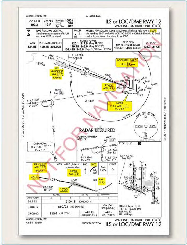
Figure 4-20. Example approaches using autopilot.
Transition to a Visual Approach
The transition from instrument flight to visual flight during an instrument approach can be very challenging, especially during low visibility operations. Aircrews should use caution when transitioning to a visual approach at times of shallow fog. Adequate visibility may not exist to allow flaring of the aircraft. Aircrews must always be prepared to execute a missed approach/go-around. Additionally, single-pilot operations make the transition even more challenging. Approaches with vertical guidance add to the safety of the transition to visual because the approach is already stabilized upon visually acquiring the required references for the runway. 100 to 200 feet prior to reaching the DA, DH, or MDA, most of the PM’s attention should be outside of the aircraft in order to visually acquire at least one visual reference for the runway, as required by the regulations. The PF should stay focused on the instruments until the PM calls out any visual aids that can be seen, or states “runway in sight.” The PF should then begin the transition to visual flight. It is common practice for the PM to call out the V/S during the transition to confirm to the PF that the instruments are being monitored, thus allowing more of the PF’s attention to be focused on the visual portion of the approach and landing. Any deviations from the stabilized approach criteria should also be announced by the PM.
Single-pilot operations can be much more challenging because the pilot must continue to fly by the instruments while attempting to acquire a visual reference for the runway. While it is important for both pilots of a two-pilot aircraft to divide their attention between the instruments and visual references, it is even more critical for the single- pilot operation. The flight visibility must also be at least the visibility minimum stated on the instrument approach chart, or as required by regulations. CAT II and III approaches have specific requirements that may differ from CAT I precision or non-precision approach requirements regarding transition to visual and landing. This information can be found in the operator’s OpSpecs or FOM.
The visibility published on an approach chart is dependent on many variables, including the height above touchdown for straight-in approaches or height above airport elevation for circling approaches. Other factors include the approach light system coverage, and type of approach procedure,
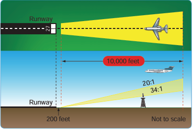
such as precision, non-precision, circling or straight-in. Another factor determining the minimum visibility is the penetration of the 34:1 and 20:1 surfaces. These surfaces are inclined planes that begin 200 feet out from the runway and extend outward to the DA point (for approaches with vertical guidance), the VDP location (for non-precision approaches) and 10,000 feet for an evaluation to a circling runway. If there is a penetration of the 34:1 surface, the published visibility can be no lower than three-fourths SM. If there is penetration of the 20:1 surface, the published visibility can be no lower than 1 SM with a note prohibiting approaches to the affected runway at night (both straight- in and circling). [Figure 4-21 ] Circling may be permitted at night if penetrating obstacles are marked and lighted. If the penetrating obstacles are not marked and lighted, a note is published that night circling is “Not Authorized.” Pilots should be aware of these penetrating obstacles when entering the visual and/or circling segments of an approach and take adequate precautions to avoid them. For RNAV approaches only, the presence of a grey shaded line from the MDA to the runway symbol in the profile view is an indication that the visual segment below the MDA is clear of obstructions on the 34:1 slope. Absence of the gray shaded area indicates the 34:1 OCS is not free of obstructions. [Figure 4-22]
Missed Approach
Many reasons exist for executing a missed approach. The primary reasons, of course, are that the required flight visibility prescribed in the IAP being used does not exist when natural vision is used under 14 CFR Part 91, § 91.175c, the required enhanced flight visibility is less than that prescribed in the IAP when an EFVS is used under 14 CFR Part 91, § 91.176, or the required visual references for the runway cannot be seen upon arrival at the DA, DH, or MAP. In addition, according to 14 CFR Part 91, the aircraft must continuously be in a position from which a descent to a landing on the intended runway can be made at a
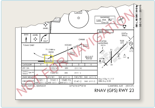
Figure 4-22. RNAV approach Fort Campbell, Kentucky.
normal rate of descent using normal maneuvers, and for operations conducted under Part 121 or 135, unless that descent rate allows touchdown to occur within the TDZ of the runway of intended landing. CAT II and III approaches call for different visibility requirements as prescribed by the FAA Administrator. Prior to initiating an instrument approach procedure, the pilot should assess the actions to be taken in the event of a balked (rejected) landing beyond the missed approach point or below the MDA or DA (H) considering the anticipated weather conditions and available aircraft performance. 14 CFR 91.175(e) authorizes the pilot to fly an appropriate missed approach procedure that ensures obstruction clearance, but it does not necessarily consider separation from other air traffic. The pilot must consider other factors such as the aircraft’s geographical location with respect to the prescribed missed approach point, direction of flight, and/ or the minimum turning altitudes in the prescribed missed approach procedure. The pilot must also consider aircraft performance, visual climb restrictions, charted obstacles, published obstacle departure procedure, takeoff visual climb requirements as expressed by nonstandard takeoff minima, other traffic expected to be in the vicinity, or other factors not specifically expressed by the approach procedures.
A clearance for an instrument approach procedure includes a clearance to fly the published missed approach procedure, unless otherwise instructed by ATC. Once descent below the DA, DH, or MDA is begun, a missed approach must be executed if the required visibility is lost or the runway environment is no longer visible, unless the loss of sight of the runway is a result of normal banking of the aircraft during a circling approach. A MAP is also required upon the execution of a rejected landing for any reason, such as men and equipment or animals on the runway, or if the approach becomes unstabilized and a normal landing cannot be performed. After the MAP in the visual segment of a non-precision approach, there may be hazards when executing a missed approach below the MDA. The published missed approach procedure provides obstacle clearance only when the missed approach is conducted on the missed approach segment from or above the missed approach point, and assumes a climb rate of 200 ft/NM or higher, as published. If the aircraft initiates a missed approach at a point other than the missed approach point, from below MDA or DA (H), or on a circling approach, obstacle clearance is not provided by following the published missed approach procedure, nor is separation assured from other air traffic in the vicinity.
The missed approach climb is normally executed at the MAP. If such a climb is initiated at a higher altitude prior to the MAP, pilots must be aware of any published climb- altitude limitations, which must be accounted for when commencing an early climb. Figure 4-23 gives an example of an altitude restriction that would prevent a climb between the FAF and MAP. In this situation, the Orlando Executive ILS or LOC RWY 7 approach altitude is restricted at the BUVAY 3 DME fix to prevent aircraft from penetrating the overlying protected airspace for approach routes into Orlando International Airport. If a missed approach is initiated before reaching BUVAY, a pilot may be required to continue descent to 1,200 feet before proceeding to the MAP and executing the missed approach climb instructions. In addition to the missed approach notes on the chart, the Pilot Briefing Information icons in the profile view indicate the initial vertical and lateral missed approach guidance.
The missed approach course begins at the MAP and continues until the aircraft has reached the designated fix and a holding pattern has been entered. [Figure 4-24] In these circumstances, ATC normally issues further instructions before the aircraft reaches the final fix of the missed approach course. It is also common for the designated fix to be an IAF so that another approach attempt can be made without having to fly from the holding fix to an IAF.
In the event a balked (rejected) landing occurs at a position other than the published missed approach point, the pilot should contact ATC as soon as possible to obtain an amended clearance. If unable to contact ATC for any reason, the pilot should attempt to re−intercept a published segment of the missed approach and comply with route and altitude instructions. If unable to contact ATC, and in the pilot’s judgment it is no longer appropriate to fly the published missed approach procedure, then consider either maintaining visual conditions (if possible) and reattempt a landing, or a circle−climb over the airport. Should a missed approach become necessary when operating to an airport that is not served by an operating control tower, continuous contact with an air traffic facility may not be possible. In this case, the pilot should execute the appropriate go−around/missed approach procedure without delay and contact ATC when able to do so.
As shown in Figure 4-25 , there are many different ways that the MAP can be depicted, depending on the type of approach. On all approach charts, it is depicted in the profile and plan views by the end of the solid course line and the beginning of the dotted missed approach course line for the top-line/ lowest published minima. For a precision approach, the MAP is the point at which the aircraft reaches the DA or DH while on the glideslope/ glidepath. MAPs on non-precision approaches can be determined in many different ways. If the primary NAVAID is on the airport, and either a VOR or NDB approach is being executed, the MAP is normally the point at which the aircraft passes the NAVAID.
On some non-precision approaches, the MAP is given as a fixed distance with an associated time from the FAF to the MAP based on the groundspeed of the aircraft. A table on the lower right or left hand side of the approach chart shows the distance in NM from the FAF to the MAP and the time it takes at specific groundspeeds, given in 30 knot increments. Pilots must determine the approximate groundspeed and time based on the approach speed and true airspeed of their aircraft and the current winds along the final approach course. A clock or stopwatch should be started at the FAF of an approach requiring this method. Many non-precision approaches designate a specific fix as the MAP. These can be identified by a course (LOC or VOR) and DME, a cross radial from a VOR, or an RNAV (GPS) waypoint. Obstacles or terrain in the missed approach segment may require a steeper climb gradient than the standard 200 ft/NM. If a steeper climb gradient is required, a note is published on the approach chart plan view with the penetration description and examples of the required FPM rate of climb for a given groundspeed (future charting uses climb gradient). An alternative is normally charted that allows using the standard climb gradient. [Figure 4-25] In this example, if the missed approach climb requirements cannot be met for the Burbank ILS RWY 8 chart, the alternative is to use the LOC RWY 8 that is charted separately. The LOC RWY 8, S-8 procedure has a MDA that is 400 feet higher than the ILS RWY 8, S-LOC 8 MDA and meets the standard climb gradient requirement over the terrain. For some approaches a new charting standard is requiring two sets of minimums to be published when a climb gradient greater than 200 ft/NM is required. The first set of minimums is the lower of the two, requiring a climb gradient greater than 200 ft/NM. The second set of minimums is higher, but doesn’t require a climb gradient. Shown in Figure 4-26, Barstow-Daggett (KDAG) RNAV (GPS) RWY 26 is an example where there are two LPV lines of minimums.
Example Approach Briefing
During an instrument approach briefing, the name of the airport and the specific approach procedure should be identified to allow other crewmembers the opportunity to cross-reference the chart being used for the brief. This ensures that pilots intending to conduct an instrument approach have collectively reviewed and verified the information pertinent to the approach. Figure 4-27 gives an example of the items to be briefed and their sequence. Although the following example is based on multi-crew aircraft, the process is also applicable to single- pilot operations. A complete instrument approach and operational briefing example follows.
The approach briefing begins with a general discussion of the ATIS information, weather, terrain, NOTAMs, approaches in use, runway conditions, performance considerations, expected route to the final approach course, and the traffic situation. As the discussion progresses, the items and format of the briefing become more specific. The briefing can also be used as a checklist to ensure that all items have been set up correctly. Most pilots verbally brief the specific MAP so that it is fresh in their minds and there is no confusion as to who is doing what during a missed approach. Also, it is a very good idea to brief the published missed approach even if the tower is most likely to give you alternate instructions in the event of a missed approach. A typical approach briefing might sound like the following example for a flight inbound to the Monroe Regional Airport (KMLU):
ATIS: “Monroe Regional Airport Information Bravo, time 2253 Zulu, wind 360 at 10, visibility 1 mile, mist, ceiling 300
overcast, temperature 4, dew point 3, altimeter 29.73, ILS Runway 4 approach in use, landing and departing Runway 4, advise on initial contact that you have information Bravo.”
PF: “We’re planning an ILS approach to Runway 4 at Monroe Regional Airport, page 270, effective date 22 Sep 11 to 20 Oct 11. Localizer frequency is 109.5, SABAR Locator Outer Marker is 392, Monroe VOR is 117.2, final approach course is 042º. We’ll cross SABAR at 1,483 feet barometric, decision altitude is 278 feet barometric, touchdown zone elevation is 78 feet with an airport elevation of 79 feet. MAP is climb to 2,000 feet, then climbing right turn to 3,000 feet direct Monroe VOR and hold. The MSA is 2,200 feet to the north and along our missed approach course, and 3,100 feet to the south along the final approach course. ADF or DME is required for the approach and the airport has pilot controlled lighting when the tower is closed, which does not apply to this approach. The runway has a medium intensity approach lighting system with runway alignment indicator lights and a precision approach path indicator (PAPI). We need a half- mile visibility so with one mile we should be fine. Runway length is 7,507 feet. I’m planning a flaps 30 approach, auto- brakes 2, left turn on Alpha or Charlie 1 then Alpha, Golf to the ramp. With a left crosswind, the runway should be slightly to the right. I’ll use the autopilot until we break out and, after landing, I’ll slow the aircraft straight ahead until you say you have control and I’ll contact ground once we are clear of the runway. In the case of a missed approach, I’ll press TOGA (Take-off/Go-Around button used on some turbojets), call ‘go-around thrust, flaps 15, positive climb, gear up, set me up,’ climb straight ahead to 2,000 feet then climbing right turn to 3,000 feet toward Monroe or we’ll follow the tower’s instructions. Any questions?”
PM: “I’ll back up the auto-speedbrakes. Other than that, I don’t have any questions.”
Instrument Approach Procedure Segments
An instrument approach may be divided into as many as four approach segments: initial, intermediate, final, and missed approach. Additionally, feeder routes provide a transition from the en route structure to the IAF. FAA Order 8260.3 criteria provides obstacle clearance for each segment of an approach procedure as shown in Figure 4-28.
Feeder Routes
By definition, a feeder route is a route depicted on IAP charts to designate routes for aircraft to proceed from the en route structure to the IAF. [Figure 4-29 ] Feeder routes, also referred to as approach transitions, technically are not considered approach segments but are an integral part of many IAPs. Although an approach procedure may have several feeder routes, pilots normally choose the one closest to the en route arrival point. When the IAF is part of the en route structure, there may be no need to designate additional routes for aircraft to proceed to the IAF.
When a feeder route is designated, the chart provides the course or bearing to be flown, the distance, and the minimum altitude. En route airway obstacle clearance criteria apply to feeder routes, providing 1,000 feet of obstacle clearance (2,000 feet in mountainous areas).
Terminal Routes
In cases where the IAF is part of the en route structure and feeder routes are not required, a transition or terminal route is still needed for aircraft to proceed from the IAF to the intermediate fix (IF). These routes are initial approach segments because they begin at the IAF. Like feeder routes, they are depicted with course, minimum altitude, and distance to the IF. Essentially, these routes accomplish the same thing as feeder routes but they originate at an IAF, whereas feeder routes terminate at an IAF. [Figure 4-30 ]
DME Arcs
DME arcs also provide transitions to the approach course, but DME arcs are actually approach segments while feeder routes, by definition, are not. When established on a DME arc, the aircraft has departed the en route phase and has begun the approach and is maneuvering to enter an intermediate or final segment of the approach. DME arcs may also be used as an intermediate or a final segment, although they are extremely rare as final approach segments.
An arc may join a course at or before the IF. When joining a course at or before the IF, the angle of intersection of the arc and the course is designed so it does not exceed 120°. When the angle exceeds 90°, a radial that provides at least 2 NM of lead will be identified to assist in leading the turn on to the intermediate course. DME arcs are predicated on DME collocated with a facility providing omnidirectional course information, such as a VOR. A DME arc cannot be based on an ILS or LOC DME source because omnidirectional course information is not provided.
The ROC along the arc depends on the approach segment. For an initial approach segment, a ROC of 1,000 feet is required in the primary area, which extends to 4 NM on either side of the arc. For an intermediate segment primary area, the ROC is 500 feet. The initial and intermediate segment secondary areas extend 2 NM from the primary boundary area edge. The ROC starts at the primary area boundary edge at 500 feet and tapers to zero feet at the secondary area outer edge. [Figure 4-31 ]
Course Reversal
Some approach procedures do not permit straight-in approaches unless pilots are being radar vectored. In these situations, pilots are required to complete a procedure turn (PT) or other course reversal, generally within 10 NM of the PT fix, to establish the aircraft inbound on the intermediate or final approach segment.
If Category E airplanes are using the PT or there is a descent gradient problem, the PT distance available can be as much as 15 NM. During a procedure turn, a maximum speed of 200 knots indicated airspeed (KIAS) should be observed from first crossing the course reversal IAF through the procedure turn maneuver to ensure containment within the obstruction clearance area. Unless a holding pattern or teardrop procedure is published, the point where pilots begin the turn and the type and rate of turn are optional. If above the procedure turn minimum altitude, pilots may begin descent as soon as they cross the IAF outbound.
A procedure turn is the maneuver prescribed to perform a course reversal to establish the aircraft inbound on an intermediate or final approach course. The procedure turn or hold-in-lieu-of procedure turn is a required maneuver when it is depicted on the approach chart. However, the procedure turn or the hold-in-lieu-of PT is not permitted when the symbol “No PT” is depicted on the initial segment being flown, when a RADAR VECTOR to the final approach course is provided, or when conducting a timed approach from a holding fix.
The altitude prescribed for the procedure turn is a minimum altitude until the aircraft is established on the inbound course. The maneuver must be completed within the distance specified in the profile view. This distance is usually 10 miles. This may be reduced to five miles where only Category A or helicopter aircraft are operated. This distance may be increased to as much as 15 miles to accommodate high performance aircraft.
The pilot may elect to use the procedure turn or hold-in• lieu-of PT when it is not required by the procedure, but must first receive an amended clearance from ATC. When ATC is radar vectoring to the final approach course, or to the intermediate fix as may occur with RNAV standard instrument approach procedures, ATC may specify in the approach clearance “CLEARED STRAIGHT-IN (type) APPROACH” to ensure that the pilot understands that the procedure turn or hold-in-lieu-of PT is not to be flown. If the pilot is uncertain whether ATC intends for a procedure turn or a straight-in approach to be flown, the pilot will immediately request clarification from ATC.
On U.S. Government charts, a barbed arrow indicates the maneuvering side of the outbound course on which the procedure turn is made. Headings are provided for course reversal using the 45° type procedure turn. However, the point at which the turn may be commenced and the type and rate of turn is left to the discretion of the pilot (limited by the charted remain within XX NM distance). Some of the options are the 45° procedure turn, the racetrack pattern, the teardrop procedure turn, or the 80° procedure turn, or the 80° 260° course reversal. Racetrack entries should be conducted on the maneuvering side where the majority of protected airspace resides. If an entry places the pilot on the non-maneuvering side of the PT, correction to intercept the outbound course ensures remaining within protected airspace.
Some procedure turns are specified by procedural track. These turns must be flown exactly as depicted. These
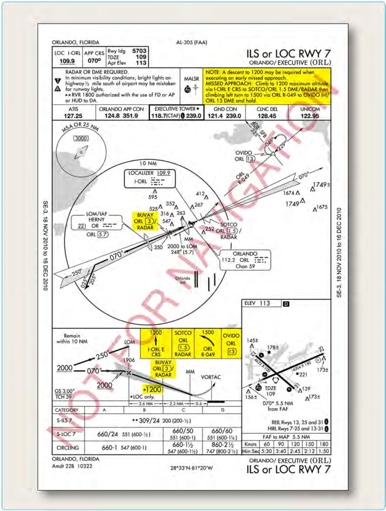
Figure 4-23. Orlando Executive Airport, Orlando, Florida, ILS RWY 7.
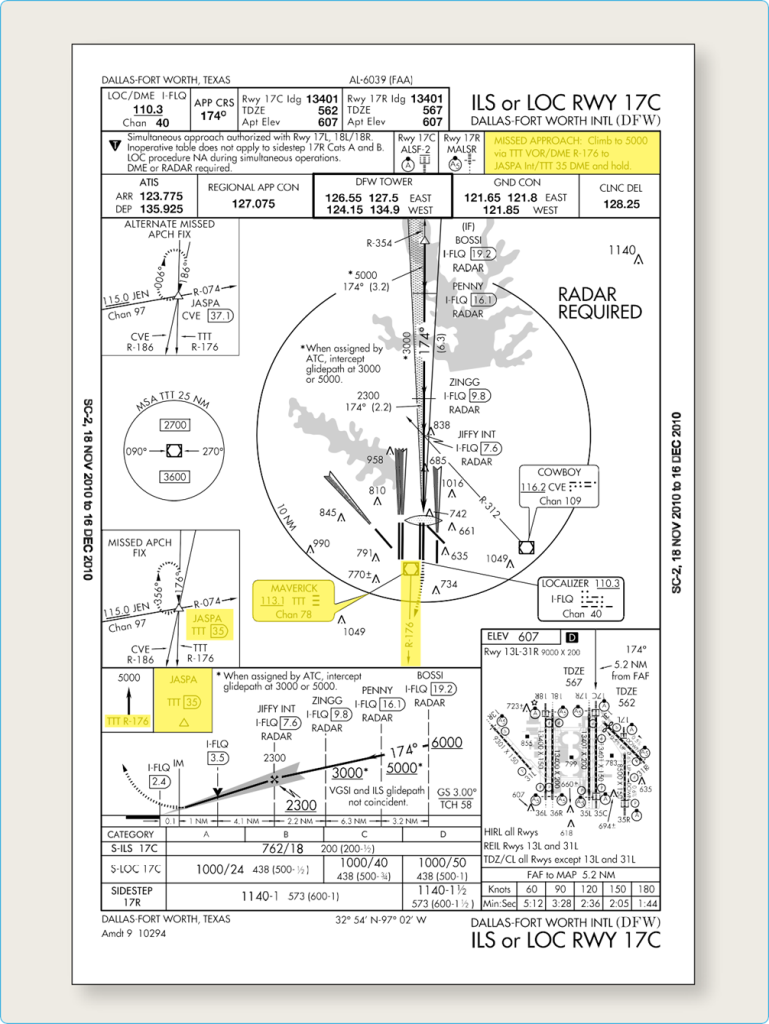
Figure 4-24 Missed approach procedures for Dallas-Fort Worth International (DFW)4
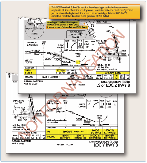
Figure 4-25. Missed approach point depiction and steeper than standard climb gradient requirements.
requirements are necessary to stay within the protected airspace and maintain adequate obstacle clearance. [Figure 4-32] A minimum of 1,000 feet of obstacle clearance is provided in the procedure turn primary area. [Figure 4-33] In the secondary area, 500 feet of obstacle clearance is provided at the inner edge, tapering uniformly to 0 feet at the outer edge.
The primary and secondary areas determine obstacle clearance in both the entry and maneuvering zones. The use of entry and maneuvering zones provides further relief from obstacles. The entry zone is established to control the obstacle clearance prior to proceeding outbound from the procedure turn fix. The maneuvering zone is established to control obstacle clearance after proceeding outbound from the procedure turn fix.
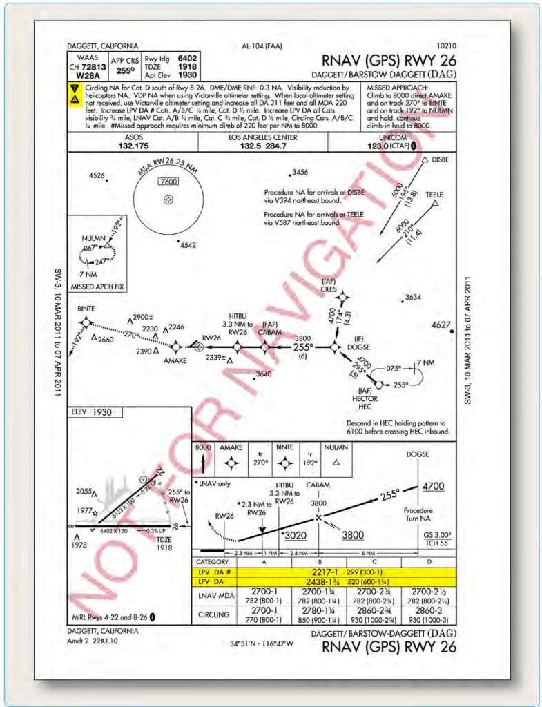
Figure 4-26. Two sets of minimums required when a climb gradient greater than 200 ft/NM is required.
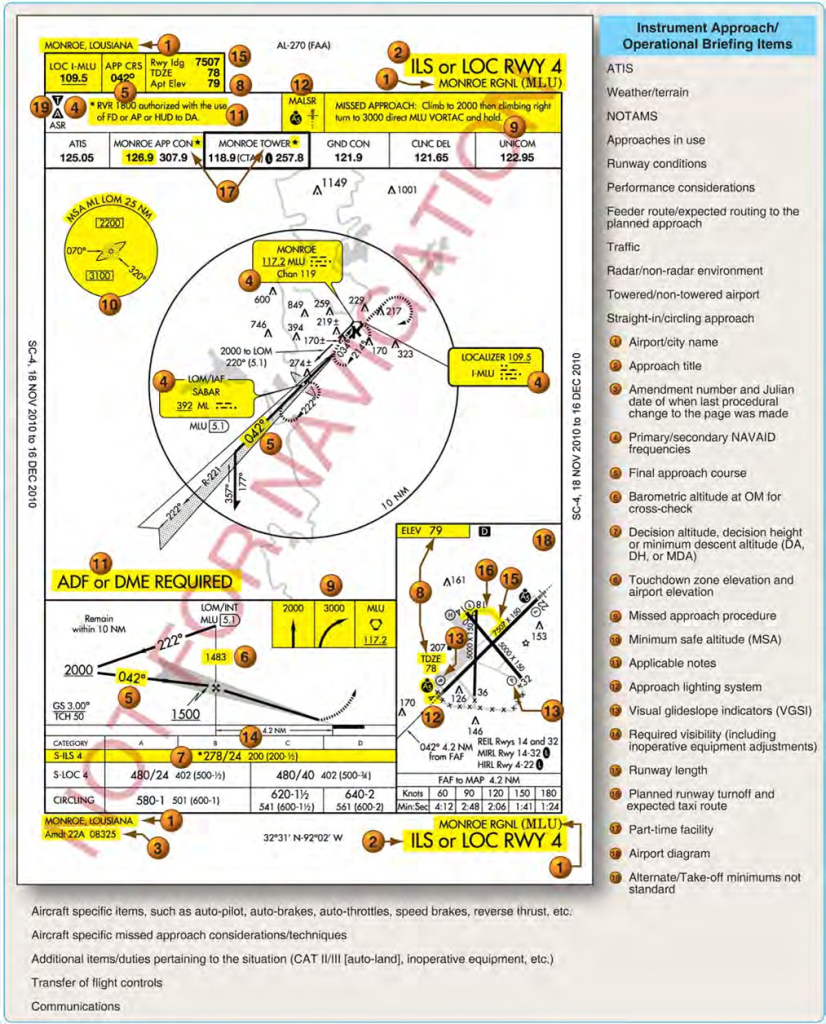
Figure 4-27. Example of approach chart briefing sequence.
Descent to the PT completion altitude from the PT fix altitude (when one has been published or assigned by ATC) must not begin until crossing over the PT fix or abeam and proceeding outbound. Some procedures contain a note in the chart profile view that says“Maintain (altitude) or above until established outbound for procedure turn.” Newer procedures simply depict an “at or above” altitude at the PT fix without a chart note. Both are there to ensure required obstacle clearance is provided in the procedure turn entry zone. Absence of a chart note or specified minimum altitude adjacent to the PT fix is an indication that descent to the procedure turn altitude can commence immediately upon crossing over the PT fix, regardless of the direction of flight. This is because the minimum altitudes in the PT entry zone and the PT maneuvering zone are the same.
A holding pattern-in-lieu-of procedure turn may be specified for course reversal in some procedures. In such cases, the holding pattern is established over an intermediate fix or a FAF. The holding pattern distance or time specified in the profile view must be observed. For a hold-in-lieu-of PT, the holding pattern direction must be flown as depicted and the specified leg length/timing must not be exceeded. Maximum holding airspeed limitations as set forth for all holding patterns apply. The holding pattern maneuver is completed when the aircraft is established on the inbound course after executing the appropriate entry. If cleared for the approach prior to returning to the holding fix and the aircraft is at the prescribed altitude, additional circuits of the holding pattern are not necessary nor expected by ATC. If pilots elect to make additional circuits to lose excessive altitude or to become better established on course, it is their responsibility to so advise ATC upon receipt of their approach clearance. Refer to the AIM section 5-4-9 for additional information on holding procedures.
Initial Approach Segment
The purposes of the initial approach segment are to provide a method for aligning the aircraft with the intermediate or final approach segment and to permit descent during the alignment. This is accomplished by using a DME arc, a course reversal, such as a procedure turn or holding pattern, or by following a terminal route that intersects the final approach course. The initial approach segment begins at an IAF and usually ends where it joins the intermediate approach segment or at an IF. The letters IAF on an approach chart indicate the location of an IAF and more than one may be available. Course, distance, and minimum altitudes are also provided for initial approach segments. A given procedure may have several initial approach segments. When more than one exists, each joins a common intermediate segment, although not necessarily at the same location.
Many RNAV approaches make use of a dual-purpose IF/ IAF associated with a hold-in-lieu-of PT (HILO) anchored at the Intermediate Fix. The HILO forms the Initial Approach Segment when course reversal is required.
When the PT is required, it is only necessary to enter the holding pattern to reverse course. The dual purpose fix functions as an IAF in that case. Once the aircraft has entered the hold and is returning to the fix on the inbound course, the dual-purpose fix becomes an IF, marking the beginning of the intermediate segment.
ATC may provide a vector to an IF at an angle of 90 degrees or less and specify “Cleared Straight-in (type) Approach”. In those cases, the radar vector is providing the initial approach segment and the pilot should not fly the PT without a clearance from ATC.
Occasionally, a chart may depict an IAF, although there is no initial approach segment for the procedure. This usually occurs at a point located within the en route structure where the intermediate segment begins. In this situation, the IAF signals the beginning of the intermediate segment.
Intermediate Approach Segment
The intermediate segment is designed primarily to position the aircraft for the final descent to the airport. Like the feeder route and initial approach segment, the chart depiction of the intermediate segment provides course, distance, and minimum altitude information.
The intermediate segment, normally aligned within 30° of the final approach course, begins at the IF, or intermediate point, and ends at the beginning of the final approach segment. In some cases, an IF is not shown on an approach chart. In this situation, the intermediate segment begins at a point where you are proceeding inbound to the FAF, are properly aligned with the final approach course, and are located within the prescribed distance prior to the FAF. An instrument approach that incorporates a procedure turn is the most common example of an approach that may not have a charted IF. The intermediate segment in this example begins when you intercept the inbound course after completing the procedure turn. [Figure 4-34]
Final Approach Segment
The final approach segment for an approach with vertical guidance or a precision approach begins where the glideslope/glidepath intercepts the minimum glideslope/ glidepath intercept altitude shown on the approach chart. If ATC authorizes a lower intercept altitude, the final approach segment begins upon glideslope/glidepath
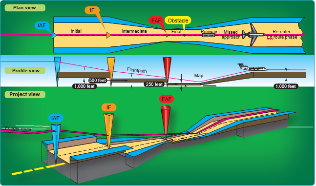
Figure 4-28. Approach segments and obstacle clearance.
interception at that altitude. For a non-precision approach, the final approach segment begins either at a designated FAF, which is depicted as a cross on the profile view, or at the point where the aircraft is established inbound on the final approach course. When a FAF is not designated, such as on an approach that incorporates an on-airport VOR or NDB, this point is typically where the procedure turn intersects the final approach course inbound. This point is referred to as the final approach point (FAP). The final approach segment ends at either the designated MAP or upon landing.
There are three types of procedures based on the final approach course guidance:
- Precision approach (PA)—an instrument approach based on a navigation system that provides course and glidepath deviation information meeting precision standards of ICAO Annex 10. For example, PAR, ILS, and GLS are precision approaches.
- Approach with vertical guidance (APV) —an instrument approach based on a navigation system that is not required to meet the precision approach standards of ICAO Annex 10, but provides course and glidepath deviation information. For example, Baro-VNAV, LDA with glidepath, LNAV/VNAV and LPV are APV approaches.
- Non-precision approach (NPA)—an instrument approach based on a navigation system that provides course deviation information but no glidepath deviation information. For example, VOR, TACAN, LNAV, NDB, LOC, and ASR approaches are examples of NPA procedures.
Missed Approach Segment
The missed approach segment begins at the MAP and ends at a point or fix where an initial or en route segment begins. The actual location of the MAP depends upon the type of approach you are flying. For example, during a precision or an APV approach, the MAP occurs at the DA or DH on the glideslope/glidepath. For non-precision approaches, the MAP is either a fix, NAVAID, or after a specified period of time has elapsed after crossing the FAF.
Approach Clearance
According to FAA Order 7110.65, ATC clearances authorizing instrument approaches are issued on the basis that if visual contact with the ground is made before the approach is completed, the entire approach procedure is followed unless the pilot receives approval for a contact approach, is cleared for a visual approach, or cancels the IFR flight plan.
Approach clearances are issued based on known traffic. The receipt of an approach clearance does not relieve the pilot of his or her responsibility to comply with applicable
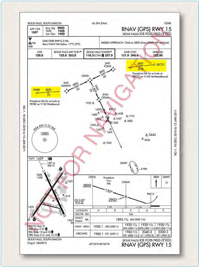
Figure 4-29. Feeder routes.
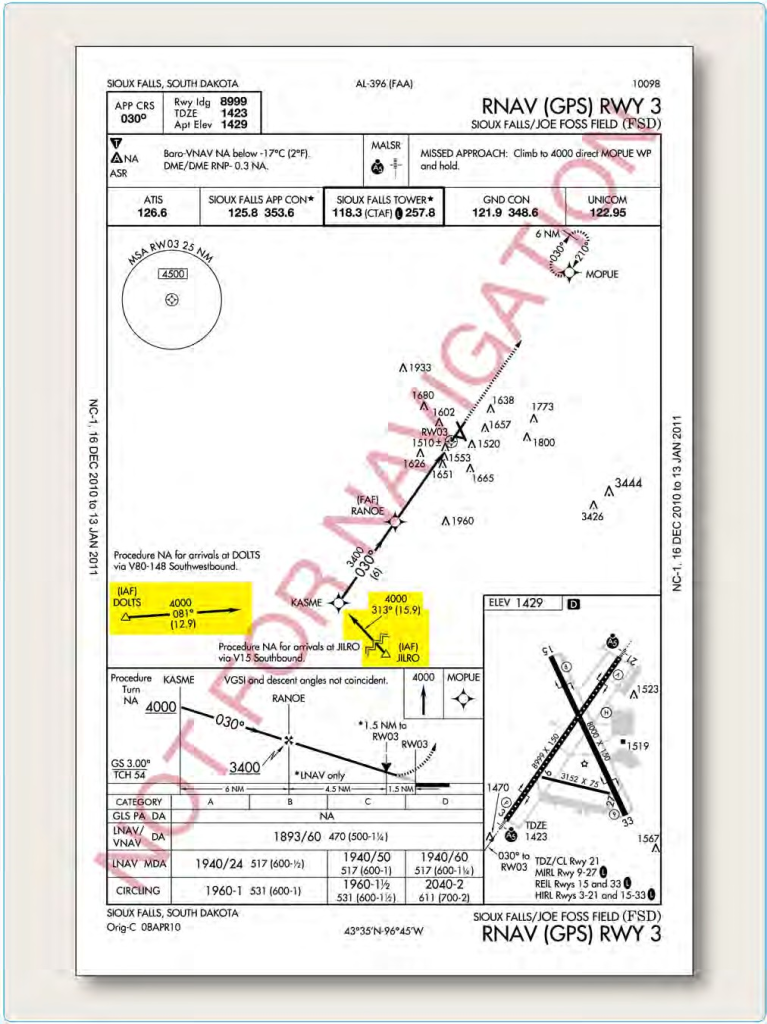
Figure 4-30. Terminal routes.
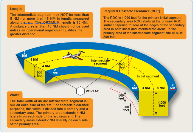
Figure 4-31. DME arc obstruction clearance.
parts of the CFRs and notations on instrument approach charts, which impose on the pilot the responsibility to comply with or act on an instruction, such as “procedure not authorized at night.” The name of the approach, as published, is used to identify the approach. Approach name items within parentheses are not included in approach clearance phraseology.
Vectors To Final Approach Course
The approach gate is an imaginary point used within ATC as a basis for vectoring aircraft to the final approach course. The gate is established along the final approach course one mile from the FAF on the side away from the airport and is no closer than 5 NM from the landing threshold. Controllers are also required to ensure the assigned altitude conforms to the following:
- For a precision approach, at an altitude not above the glideslope/glidepath or below the minimum glideslope/glidepath intercept altitude specified on the approach procedure chart.
- For a non-precision approach, at an altitude that allows descent in accordance with the published procedure.
Further, controllers must assign headings that intercept the final approach course no closer than the following table:
A typical vector to the final approach course and associated approach clearance is as follows:
“…four miles from LIMAA, turn right heading three four zero, maintain two thousand until established on the localizer, cleared ILS runway three six approach.”
Other clearance formats may be used to fit individual circumstances, but the controller should always assign an altitude to maintain until the aircraft is established on a segment of a published route or IAP. The altitude assigned must guarantee IFR obstruction clearance from the point at which the approach clearance is issued until the aircraft is established on a published route. 14 CFR Part 91, § 91.175
(j) prohibits a pilot from making a procedure turn when vectored to a FAF or course, when conducting a timed approach, or when the procedure specifies “NO PT.”
When vectoring aircraft to the final approach course, controllers are required to ensure the intercept is at least
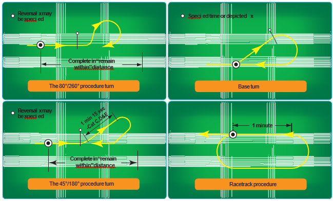
Figure 4-32. Course reversal methods.
2 NM outside the approach gate. Exceptions include the following situations, but do not apply to RNAV aircraft being vectored for a GPS or RNAV approach:
- When the reported ceiling is at least 500 feet above the MVA/MIA and the visibility is at least 3 SM (may be a pilot report (PIREP) if no weather is reported for the airport), aircraft may be vectored to intercept the final approach course closer than 2 NM outside the approach gate but no closer than the approach
gate.
- If specifically requested by the pilot, aircraft may be vectored to intercept the final approach course inside the approach gate but no closer than the FAF.
Nonradar Environment
In the absence of radar vectors, an instrument approach begins at an IAF. An aircraft that has been cleared to a holding fix that, prior to reaching that fix, is issued a clearance for an approach, but not issued a revised routing, such as,“proceed direct to…”is expected to proceed via the last assigned route, a feeder route if one is published on the approach chart, and then to commence the approach as published. If, by following the route of flight to the holding fix, the aircraft would overfly an IAF or the fix associated with the beginning of a feeder route to be used, the aircraft is expected to commence the approach using the published feeder route to the IAF or from the IAF as appropriate. The aircraft would not be expected to overfly and return to the IAF or feeder route.
For aircraft operating on unpublished routes, an altitude is assigned to maintain until the aircraft is established on a segment of a published route or IAP. (Example: “Maintain 2,000 until established on the final approach course outbound, cleared VOR/DME runway 12.”) The FAA definition of established on course requires the aircraft to be established on the route centerline. Generally, the controller assigns an altitude compatible with glideslope/ glidepath intercept prior to being cleared for the approach.
Types of Approaches
In the NAS, there are approximately 1,105 VOR stations, 916 NDB stations, and 1,194 ILS installations, including 25 LOC- type directional aids (LDAs), 11 simplified directional facilities (SDFs), and 235 LOC only facilities. As time progresses, it is the intent of the FAA to reduce navigational dependence on VOR, NDB, and other ground-based NAVAIDs and, instead, to increase the use of satellite-based navigation.
To expedite the use of RNAV procedures for all instrument pilots, the FAA has begun an aggressive schedule to develop RNAV procedures. As of 2010, the number of RNAV/ GPS approaches published in the NAS numbered
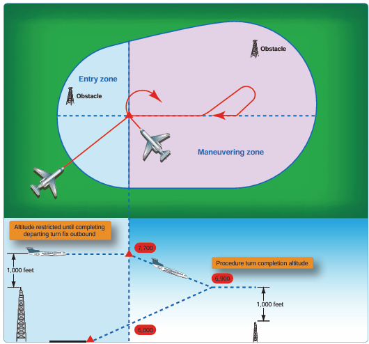
Figure 4-33. Procedure turn obstacle clearance.
10,212 – with additional procedures published every revision cycle. While it had originally been the plan of the FAA to begin decommissioning VORs, NDBs, and other ground- based NAVAIDs, the overall strategy has been changed to incorporate a majority dependence on augmented satellite navigation while maintaining a satisfactory backup system. This backup system includes retaining all CAT II and III ILS facilities and close to one-half of the existing VOR network.
Each approach is provided obstacle clearance based on the FAA Order 8260.3 TERPS design criteria as appropriate for the surrounding terrain, obstacles, and NAVAID availability. Final approach obstacle clearance is different for every type of approach but is guaranteed from the start of the final approach segment to the runway (not below the MDA for non-precision approaches) or MAP, whichever occurs last within the final approach area. It is dependent upon the pilot to maintain an appropriate flight path within the boundaries of the final approach area and maintain obstacle clearance.
There are numerous types of instrument approaches available for use in the NAS including RNAV (GPS), ILS, MLS, LOC, VOR, NDB, SDF, and radar approaches. Each approach has separate and individual design criteria, equipment requirements, and system capabilities.
Visual and Contact Approaches
To expedite traffic, ATC may clear pilots for a visual approach in lieu of the published approach procedure if
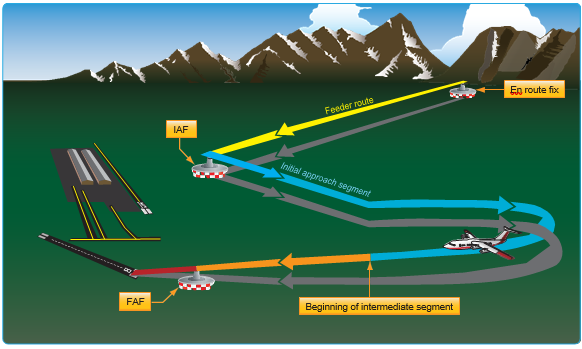
Figure 4-34. Approach without a designated IF.
flight conditions permit. Requesting a contact approach may be advantageous since it requires less time than the published IAP and provides separation from IFR and special visual flight rules (SVFR) traffic. A contact or visual approach may be used in lieu of conducting a SIAP, and both allow the flight to continue as an IFR flight to landing while increasing the efficiency of the arrival.
Visual Approaches
When it is operationally beneficial, ATC may authorize pilots to conduct a visual approach to the airport in lieu of the published IAP. A pilot, or the controller,
can initiate a visual approach. Before issuing a visual approach clearance, ATC must verify that the pilot has the airport, or a preceding aircraft that they are to follow, in sight. Once the pilot reports the airport, or
aircraft, in sight, the pilot is responsible to maintain safe
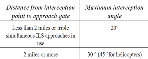
altitudes and separation from other aircraft. If the pilot reports the airport in sight but does not see the aircraft they are assigned to follow, ATC may still issue the visual approach clearance but the controller maintains responsibility for aircraft separation (including wake turbulence separation). Once pilots report the aircraft in sight, they assume the responsibilities for their own separation and wake turbulence avoidance.
A visual approach is an ATC authorization for an aircraft on an IFR flight plan to proceed visually to the airport of intended landing; it is not an IAP. Also, there is no missed approach segment. An aircraft unable to complete a visual approach must be handled as any other go-around and appropriate separation must be provided. A vector for a visual approach may be initiated by ATC if the reported ceiling at the airport of intended landing is at least 500 feet above the MVA/MIA and the visibility is 3 SM or greater. At airports without weather reporting service, there must be reasonable assurance through area weather reports and PIREPs that descent and approach to the airport can be made visually, and the pilot must be informed that weather information is not available.
The visual approach clearance is issued to expedite the flow of traffic to an airport. It is authorized when the ceiling is reported or expected to be at least 1,000 feet AGL and the visibility is at least 3 SM. Pilots must remain clear of the clouds at all times while conducting a visual approach. At an airport with a control tower, pilots may be cleared to fly a visual approach to one runway while others are conducting VFR or IFR approaches to another parallel, intersecting, or converging runway. Also, when radar service is provided, it is automatically terminated when the controller advises pilots to change to the tower or advisory frequency. While conducting a visual approach, the pilot is responsible for providing safe obstacle clearance.
Contact Approaches
If conditions permit, pilots can request a contact approach, which is then authorized by the controller. A contact approach cannot be initiated by ATC. This procedure may be used instead of the published procedure to expedite arrival, as long as the airport has a SIAP the reported ground visibility is at least 1 SM, and pilots are able to remain clear of clouds with at least one statute mile flight visibility throughout the approach. Some advantages of a contact approach are that it usually requires less time than the published instrument procedure, it allows pilots to retain the IFR clearance, and provides separation from IFR and SVFR traffic. On the other hand, obstruction clearances and VFR traffic avoidance becomes the pilot’s responsibility. Unless otherwise restricted, the pilot may find it necessary to descend, climb, or fly a circuitous route to the airport to maintain cloud clearance or terrain/ obstruction clearance.
The main differences between a visual approach and a contact approach are: a pilot must request a contact approach, while a visual approach may be assigned by ATC or requested by the pilot; and a contact approach may be
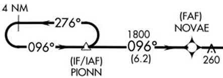
approved with one mile visibility if the flight can remain clear of clouds, while a visual approach requires the pilot to have the airport in sight, or a preceding aircraft to be followed, and the ceiling must be at least 1,000 feet AGL with at least 3 SM visibility.
Charted Visual Flight Procedures
A charted visual flight procedure (CVFP) may be established at some airports with control towers for environmental or noise considerations, as well as when necessary for the safety and efficiency of air traffic operations. Designed primarily for turbojet aircraft, CVFPs depict prominent landmarks, courses, and recommended altitudes to specific runways. When pilots are flying the Roaring Fork Visual RWY 15, shown in Figure 4-35, mountains, rivers, and towns provide guidance to Aspen, Colorado’s Sardy Field instead of VORs, NDBs, and DME fixes.
Pilots must have a charted visual landmark or a preceding aircraft in sight, and weather must be at or above the published minimums before ATC will issue a CVFP clearance. ATC will clear pilots for a CVFP if the reported ceiling at the airport of intended landing is at least 500 feet above the MVA/MIA, and the visibility is 3 SM or more, unless higher minimums are published for the particular CVFP. When accepting a clearance to follow traffic, the pilot is responsible for maintaining a safe altitude, approach interval and wake turbulence separation from other aircraft Pilots must advise ATC if unable at any point to continue a charted visual approach or if the pilot loses sight of the preceding aircraft.
RNAV Approaches
Because of the complications with database coding, naming conventions were changed in January 2001 to accommodate all approaches using RNAV equipment into one classification which is RNAV. This classification includes both ground- based and satellite dependent systems. Eventually all approaches that use some type of RNAV will reflect RNAV in the approach title.
This changeover is being made to reflect two shifts in instrument approach technology. The first shift is the use of the RNP concept outlined in Chapter 1, Departure Procedures, in which a single performance standard concept is being implemented for departure/approach procedure design. Through the use of RNP, the underlying system of navigation may not be required, provided the aircraft can maintain the appropriate RNP standard. The second shift is advanced avionics systems, such as FMS, used by most airlines, needed a new navigation standard by which RNAV could be fully integrated into the instrument approach system.
An FMS uses multi-sensor navigation inputs to produce a composite position. Essentially, the FMS navigation function automatically blends or selects position sensors to compute aircraft position. Instrument approach charts and RNAV databases needed to change to reflect these issues. A complete discussion of airborne navigation databases is included in Chapter 6, Airborne Navigation Databases. Due to the multi- faceted nature of RNAV, new approach criteria have been developed to accommodate the design of RNAV instrument approaches. This includes criteria for terminal arrival areas (TAAs), RNAV basic approach criteria, and specific final approach criteria for different types of RNAV approaches.
Terminal Arrival Areas
The Terminal Arrival Area (TAA) provides a transition from the en route structure to the terminal environment with little required pilot/air traffic control interface for aircraft equipped with Area Navigation (RNAV) systems. TAAs provide minimum altitudes with standard obstacle clearance when operating within the TAA boundaries. TAAs are primarily used on RNAV approaches but may be used on an ILS approach when RNAV is the sole means for navigation to the IF; however, they are not normally used in areas of heavy concentration of air traffic . [Figure 4-36]
The basic design of the RNAV procedure underlying the TAA is normally the “T” design (also called the “Basic T”). The “T” design incorporates two IAFs plus a dual purpose IF/IAF that functions as both an intermediate fix and an initial approach fix. The T configuration continues from the IF/IAF to the FAF and then to the MAP. The two base leg IAFs are typically aligned in a straight-line perpendicular to the intermediate course connecting at the IF/IAF. A Hold- in-Lieu-of Procedure Turn (HILO) is anchored at the IF/IAF and depicted on U.S. Government publications using the “hold−in−lieu−of−PT” holding pattern symbol. When the HILO is necessary for course alignment and/or descent, the dual purpose IF/IAF serves as an IAF during the entry into the pattern. Following entry into the HILO pattern and when flying a route or sector labeled “NoPT,” the dual- purpose fix serves as an IF, marking the beginning of the Intermediate Segment.
The standard TAA based on the “T” design consists of three areas defined by the IAF legs and the intermediate segment course beginning at the IF/IAF. These areas are called the straight−in, left−base, and right−base areas. [Figure 4-36] TAA area lateral boundaries are identified by magnetic courses TO the IF/IAF. The straight−in area can be further divided into pie−shaped sectors with the boundaries identified by magnetic courses TO the IF/ IAF, and may contain step-down sections defined by arcs based on RNAV distances from the IF/IAF.
Entry from the terminal area onto the procedure is normally accomplished via a no procedure turn (NoPT) routing or via a course reversal maneuver. The published procedure will be annotated “NoPT” to indicate when the course reversal is not authorized when flying within a particular TAA sector [Figures 4-36 and 4-37]. Otherwise, the pilot is expected to execute the course reversal under the provisions of 14 CFR § 91.175. The pilot may elect to use the course reversal pattern when it is not required by the procedure, but must receive clearance from air traffic control before beginning the procedure.
ATC should not clear an aircraft to the left base leg or right base leg IAF within a TAA at an intercept angle exceeding 90 degrees. Pilots must not execute the HILO course reversal when the sector or procedure segment is labeled “NoPT.”
ATC may clear aircraft direct to the fix labeled IF/IAF if the course to the IF/IAF is within the straight-in sector labeled “NoPT” and the intercept angle does not exceed 90 degrees. Pilots are expected to proceed direct to the IF/ IAF and accomplish a straight-in approach. Do not execute HILO course reversal. Pilots are also expected to fly the straight−in approach when ATC provides radar vectors and monitoring to the IF/IAF and issues a“straight-in” approach clearance; otherwise, the pilot is expected to execute the HILO course reversal. (See AIM Paragraph 5−4−6, Approach Clearance)
On rare occasions, ATC may clear the aircraft for an approach at the airport without specifying the approach procedure by name or by a specific approach (e.g., “cleared RNAV Runway 34 approach”) without specifying a particular IAF. In either case, the pilot should proceed direct to the IAF or to the IF/IAF associated with the sector that the aircraft will enter the TAA and join the approach course from that point and if required by that sector (i.e., sector is not labeled “NoPT), complete the HILO course reversal.
Note: If approaching with a TO bearing that is on a sector boundary, the pilot is expected to proceed in accordance with a “NoPT” routing unless otherwise instructed by ATC.
Altitudes published within the TAA replace the MSA alti• tude. However, unlike MSA altitudes the TAA altitudes are operationally usable altitudes. These altitudes provide at least 1,000 feet of obstacle clearance, and more in moun• tainous areas. It is important that the pilot knows which area of the TAA that the aircraft will enter in order to com• ply with the minimum altitude requirements. The pilot can determine which area of the TAA the aircraft will enter by determining the magnetic bearing of the aircraft TO the fix labeled IF/IAF. The bearing should then be com• pared to the published lateral boundary bearings that define the TAA areas. Do not use magnetic bearing to the right-base or left-base IAFs to determine position.
An ATC clearance direct to an IAF or to the IF/IAF with• out an approach clearance does not authorize a pilot to descend to a lower TAA altitude. If a pilot desires a low•
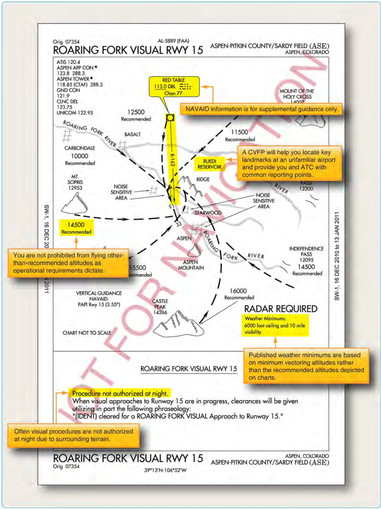
Figure 4-35. Charted visual flight procedures (CVFP).
er altitude without an approach clearance, request the lower TAA altitude from ATC. Pilots not sure of the clear• ance should confirm their clearance with ATC or request a specific clearance. Pilots entering the TAA with two−way radio communications failure (14 CFR § 91.185, IFR Op• erations: Two−way Radio Communications Failure), must maintain the highest altitude prescribed by 14 CFR § 91.185(c)(2) until arriving at the appropriate IAF.
Once cleared for the approach, pilots may descend in the TAA sector to the minimum altitude depicted within the defined area/subdivision, unless instructed otherwise by air traffic control. Pilots should plan their descent within the TAA to permit a normal descent from the IF/IAF to the FAF.
U.S. Government charts depict TAAs using icons located in the plan view outside the depiction of the actual ap• proach procedure. Use of icons is necessary to avoid ob• scuring any portion of the “T” procedure (altitudes, cours• es, minimum altitudes, etc.). The icon for each TAA area will be located and oriented on the plan view with respect to the direction of arrival to the approach procedure, and will show all TAA minimum altitudes and sector/radius subdivisions. The IAF for each area of the TAA is included on the icon where it appears on the approach to help the pilot orient the icon to the approach procedure. The IAF name and the distance of the TAA area boundary from the IAF are included on the outside arc of the TAA area icon.
TAAs may be modified from the standard size and shape to accommodate operational or ATC requirements. Some areas may be eliminated, while the other areas are ex• panded. The “T” design may be modified by the proce• dure designers where required by terrain or ATC consider• ations. For instance, the “T” design may appear more like a regularly or irregularly shaped “Y,” an upside down “L,” or an “I.”
When an airway does not cross the lateral TAA boundar• ies, a feeder route will be established from an airway fix or NAVAID to the TAA boundary to provide a transition from the en route structure to the appropriate IAF. Each feeder route will terminate at the TAA boundary and will be aligned along a path pointing to the associated IAF. Pilots should descend to the TAA altitude after crossing the TAA boundary and cleared for the approach by ATC.
Each waypoint on the “T” is assigned a pronounceable 5− letter name, except the missed approach waypoint. These names are used for ATC communications, RNAV data• bases, and aeronautical navigation products. The missed approach waypoint is assigned a pronounceable name when it is not located at the runway threshold.
RNAV Approach Types
RNAV encompasses a variety of underlying navigation systems and, therefore, approach criteria. This results in different sets of criteria for the final approach segment of various RNAV approaches. RNAV instrument approach criteria address the following procedures:
- GPS overlay of pre-existing nonprecision approaches.
- VOR/DME based RNAV approaches.
- Stand-alone RNAV (GPS) approaches.
- RNAV (GPS) approaches with vertical guidance (APV).
- RNAV (GPS) precision approaches (WAAS and LAAS).
GPS Overlay of Nonprecision Approach
The original GPS approach procedures provided authorization to fly non-precision approaches based on conventional, ground-based NAVAIDs. Many of these approaches have been converted to stand-alone approaches, and the few that remain are identified by the name of the procedure and “or GPS.” These GPS non- precision approaches are predicated upon the design criteria of the ground-based NAVAID used as the basis of the approach. As such, they do not adhere to the RNAV design criteria for stand-alone GPS approaches, and are not considered part of the RNAV (GPS) approach classification for determining design criteria. [Figure 4-38]
GPS Stand-Alone/RNAV (GPS) Approach
The number of GPS stand-alone approaches continues to decrease as they are replaced by RNAV approaches. RNAV (GPS) approaches are named so that airborne navigation databases can use either GPS or RNAV as the title of the approach. This is required for non-GPS approach systems, such as VOR/DME based RNAV systems. In the past, these approaches were often referred to as “stand-alone GPS” approaches. They are considered non-precision approaches, offering only LNAV and circling minimums. Precision minimums are not authorized, although LNAV/ VNAV minimums may be published and used as long as the on-board system is capable of providing approach approved VNAV. The RNAV (GPS) Runway 14 approach for Lincoln, Nebraska, incorporates only LNAV and circling minimums. [Figure 4-39] For a non-vertically guided straight-in RNAV (GPS) approach, the final approach course must be aligned within 15° of the extended runway centerline. The final approach segment should not exceed 10 NM, and when it exceeds 6 NM, a stepdown fix is typically incorporated. A minimum
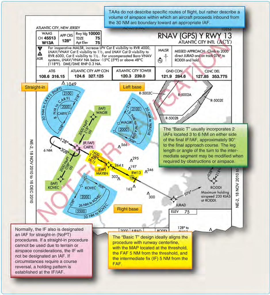
Figure 4-36. Terminal arrival area (TAA) design “basic T.”
of 250 feet obstacle clearance is also incorporated into the final approach segment for straight-in approaches, and a maximum 400-ft/NM descent gradient is permitted.
The approach design criteria are different for approaches that use vertical guidance provided by a Baro-VNAV system. Because the Baro-VNAV guidance is advisory and not primary, Baro-VNAV approaches are not authorized in areas of hazardous terrain, nor are they authorized when a remote altimeter setting is required. Due to the inherent problems associated with barometric readings and cold temperatures, these procedures are also temperature limited. Additional approach design criteria for RNAV Approach Construction Criteria can be found in the appropriate FAA Order 8260-series orders.
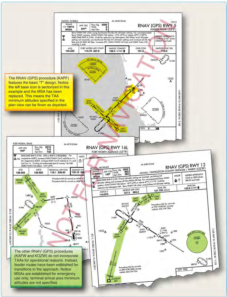
Figure 4-37. RNAV approaches with and without TAAs.
RNAV (GPS) Approach Using WAAS
WAAS was commissioned in July 2003, with IOC. Although precision approach capability is still in the future, WAAS currently provides a type of APV known as LPV. WAAS can support the following minima types: LPV, LNAV/VNAV, LP, and LNAV. Approach minima as low as 200 feet HAT and 1/2 SM visibility is possible, even though LPV is not considered a precision approach. WAAS covers 95 percent of the country 95 percent of the time.
Note: WAAS avionics receive an airworthiness approval in accordance with Technical Standard Order ( TSO) C145, Airborne Navigation Sensors Using the Global Positioning System (GPS) Augmented by the Satellite Based Augmentation System (SBAS), or TSO-146, Stand- Alone Airborne Navigation Equipment Using the Global Positioning System (GPS) Augmented by the Satellite Based Augmentation System (SBAS), and installed in accordance with AC 20-138C, Airworthiness Approval of Positioning and Navigation Systems.
Precision approach capability will become available as more GBAS (LAAS) approach types become operational. GBAS (LAAS) further increases the accuracy of GPS and improves signal integrity warnings. Precision approach capability requires obstruction planes and approach lighting systems to meet Part 77 standards for ILS approaches. This delays the implementation of RNAV (GPS) precision approach capability due to the cost of certifying each runway.
ILS Approaches
Notwithstanding emerging RNAV technology, the ILS is the most precise and accurate approach NAVAID currently in use throughout the NAS. An ILS CAT I precision approach allows approaches to be made to 200 feet above the TDZE and with visibilities as low as 1,800 RVR; with CAT II and CAT III approaches allowing descents and visibility minimums that are even lower. Non-precision approach alternatives cannot begin to offer the precision or flexibility offered by an ILS. In order to further increase the approach capacity of busy airports and exploit the maximum potential of ILS technology, many different applications are in use.
An ILS system can accommodate up to 29 arrivals per hour on a single runway. Two or three parallel runways operating independently can double or triple the capacity of the airport. For air commerce, this means greater flexibility in scheduling passenger and cargo service. Capacity is increased through the use of simultaneous or converging ILS approaches, which are explained further in the corresponding paragraphs below. In order to successfully accomplish simultaneous or converging ILS approaches, flight crews and ATC have additional responsibilities. When simultaneous instrument approaches are in use, ATC advises flight crews either directly or through ATIS of the active runways. It is the pilot’s responsibility to inform ATC if unable or unwilling to execute a simultaneous approach. Pilots must comply with all ATC requests in a timely manner and maintain strict radio discipline, including using complete aircraft call signs. It is also incumbent upon the flight crew to notify ATC immediately of any problems relating to aircraft communications or navigation systems. At the very least, the approach procedure briefing should cover the entire procedure including the approach name, runway number, frequencies, final approach course, glideslope intercept altitude, DA or DH, and the missed approach instructions. The review of autopilot procedures is also appropriate when making coupled ILS approaches.
As with all approaches, the primary navigation responsibility falls upon the pilot in command. ATC instructions will be limited to ensuring aircraft separation. Additionally, MAPs are designed to diverge in order to protect all involved aircraft. ILS approaches of all types are afforded the same obstacle clearance protection and design criteria, no matter how capacity is affected by simultaneous ILS approaches. [Figure 4-40]
ILS Approach Categories
There are three general classifications of ILS approaches: CAT I, CAT II, and CAT III (autoland). The basic ILS approach is a CAT I approach and requires only that pilots be instrument rated and current, and that the aircraft be equipped appropriately. CAT II and CAT III ILS approaches have lower minimums and require special certification for operators, pilots, aircraft, and airborne/ground equipment. Because of the complexity and high cost of the equipment, CAT III ILS approaches are used primarily in air carrier and military operations. [Figure 4-41]
CAT II and III Approaches
The primary authorization and minimum RVRs allowed for an air carrier to conduct CAT II and III approaches can be found in OpSpecs Part C. CAT II and III operations allow authorized pilots to make instrument approaches in weather that would otherwise be prohibitive.
While CAT I ILS operations permit substitution of midfield RVR for TDZ RVR (when TDZ RVR is not available), CAT II ILS operations do not permit any substitutions for TDZ RVR. The TDZ RVR system is required and must be used. The TDZ RVR is controlling for all CAT II ILS operations. The weather conditions encountered in CAT III operations range from an area where visual references are adequate for manual rollout in CAT IIIa, to an area where visual references are inadequate even for taxi operations in CAT IIIc. To date, no U.S. operator has received approval for CAT IIIc in OpSpecs. Depending on the auto-flight systems, some aircraft require a DH to ensure that the aircraft is going to land in the TDZ and some require an Alert Height as a final cross-check of the performance of the auto-flight systems. These heights are based on radio altitude (RA) and can be found in the specific aircraft’s AFM. [Figure 4-42]
Both CAT II and III approaches require special ground and airborne equipment to be installed and operational, as well as special aircrew training and authorization. The OpSpecs of individual air carriers detail the requirements of these types of approaches, as well as their performance criteria. Lists of locations where each operator is approved to conduct CAT II and III approaches can also be found in the OpSpecs.
Special Authorization approaches are designed to take advantage of advances in flight deck avionics and technologies like Head-Up Displays (HUD) and automatic landings. There are extensive ground infrastructures and lighting requirements for standard CAT II/III, and the Special Authorization approaches mitigate the lack of some lighting with the modern avionics found in many aircraft today. Similar to standard CAT II/III, an air carrier must be specifically authorized to conduct Special Authorization CAT I/II in OpSpecs Part C.
Simultaneous Approaches To Parallel Runways
Airports that have two or more parallel runways may be authorized to use simultaneous parallel approaches to maximize the capacity of the airport. Depending on the runway centerline separation and ATC procedures, there are three classifications of simultaneous parallel approaches: Simultaneous dependent approaches, simultaneous independent approaches and simultaneous independent close parallel approaches. A simultaneous dependent approach differs from a simultaneous independent approach in that the minimum distance between parallel runway centerlines may be less. A staggered separation of aircraft on the adjacent final approach course is required; but there is no requirement for a No Transgression Zone (NTZ) or Final Monitor Controllers. An independent approach eliminates the need for staggered approaches and aircraft may be side by side or pass if speeds are different.
NOTE:
- Simultaneous approaches involving an RNAV approach may only be conducted when (GPS) appears in the approach title or a chart note states that GPS is required. See the“ILS Approaches” paragraph above for information about pilot responsibilities when simultaneous approaches are in use.
- Flight Director or Autopilot requirements for simultaneous operations will be annotated on the approach chart.
- Simultaneous approaches may only be conducted where instrument approach charts specifically authorize simultaneous approaches.
Simultaneous Dependent Approaches [Figure 4-46]
When simultaneous dependent approaches are provided, ATC applies specific minimum diagonal separation criteria, depending on the runway separation, between aircraft on adjacent final approach courses. Aircraft will be staggered by a minimum of 1 NM diagonally on final, depending on the distance between runway centerlines. Greater separation standards are applied when the distance between runway centerlines is greater. [Figure 4-43]
At some airports, simultaneous dependent instrument approaches can be conducted with runways spaced less than 2,500 feet with specific centerline separations and threshold staggers. ATC is permitted to apply reduced diagonal separation and special wake turbulence procedures. The lead aircraft of the dependent pair is restricted to being small or large aircraft weight type and is cleared to the lower approach. The design of the approach, aircraft weight type, and lateral separation between the two approaches provide necessary wake turbulence avoidance for this type of operation. An example of approach design to help avoid wake turbulence is that some locations use different glide slope angles on adjacent approaches; also, if applicable, staggered thresholds help. An ATIS example is: “Simultaneous ILS Runway 28 Left and ILS Runway 28 Right in use.” For further information, see FAA Orders JO 7110.65 and JO 7110.308.
Where a simultaneous approach operation is approved, sometimes each approach chart indicates the other runway(s) with which simultaneous approaches can be conducted. For example, “Simultaneous approaches authorized with runway 12L”. As procedures are revised, the chart note will be modified to indicate “Simultaneous approach authorized” but will not list the other runways or approach types as that detailed information will normally be transmitted in the ATIS or by ATC. For example, pilots flying into Sacramento, California, may encounter parallel approach procedures. [Figure 4-44] When there is no chart note stating, “Simultaneous approaches authorized”, standard separation is used between aircraft on parallel approaches.
Simultaneous Independent Approaches
Dual and triple simultaneous independent parallel instrument approaches, are authorized at certain airports with specified distances between parallel runway centerlines. As a part of the simultaneous independent approach approval, an NTZ must be established to ensure proper flight track boundaries for all aircraft. Outside of the NTZ, normal operating zones (NOZ) indicate the operating zone within which aircraft remain during normal approach operations. The NOZ between the final approach courses varies in width depending on the runway centerline spacing. The NTZ is defined as a 2,000-foot wide area located equidistant between the final approach courses in which flight is not allowed during the simultaneous operation. [Figure 4-46] Any time an aircraft breaches or is anticipated to breach the NTZ, ATC issues instructions for the threatened aircraft on the adjacent final approach course to break off the approach to avoid potential conflict.
A local controller for each runway is also required. Dedicated final monitor controllers for each runway monitor separation, track aircraft positions and issue instructions to pilots of aircraft observed deviating from the final approach course. [Figure 4-45] These operations are normally authorized for ILS, LDA and RNAV approach procedures with vertical guidance. For simultaneous parallel ILS approach operations, pilots should review the chart notes to determine whether the non-precision LOC procedure is authorized (in the event of glide slope equipment failure either in the aircraft or the ground). An example of a restriction on the use of a LOC procedure is shown in the notes on Figure 4-24: “LOC procedure NA during simultaneous operations”. Likewise, for RNAV (GPS) approaches, use of LNAV procedures are often restricted during simultaneous operations.
Triple simultaneous independent approaches are authorized provided the runway centerlines are separated by at least 3900 feet for triple straight in approaches. If one or both outside runways have an offset approach course of 2.5° to 3.0°, the spacing between those outer runways and the center runway may be reduced to 3000 feet.
Simultaneous Close Parallel Precision Runway Monitor (PRM) Approaches
Simultaneous close parallel (independent) PRM approaches are authorized for use at designated airports that have parallel runways spaced less than 4,300 feet apart. [Figure 4-47] Certain PRM approaches are referred to as Simultaneous Offset Instrument Approaches (SOIA) and are discussed in depth later in this chapter.
PRM procedures are the most efficient method of increasing approach capacity at airports with closely spaced, parallel runways. Use of PRM procedures increases airport capacity during periods of low visibility by providing ATC the capability to monitor simultaneous close parallel (independent) approaches. These PRM operations reduce delays and increase fuel savings. Traditionally the PRM system included a high-update rate radar, a high resolution ATC radar display, as well as software that can autonomously track aircraft in close to real time, with visual and aural alerts that depict the aircraft’s current position and velocity as well as displaying a ten-second projected position to the controllers. Today, most PRM operations are conducted without the need for high update rate radar, so long as all of the other requirements to conduct such approaches are met.
There are also special communications and ATC requirements for PRM approaches. PRM approaches require a final NTZ monitor controller for each runway, a separate tower controller for each runway, a PRM tower frequency, and a runway-specific PRM frequency. Each final monitor controller will have a dedicated PRM frequency, and the tower controller will have a separate common PRM frequency. Pilots transmit and receive on the common tower PRM frequency, but maintain listening watch on the final controller’s PRM frequency for their specified runway. The final monitor controller has override capability on their PRM frequency. In that way, if the common tower frequency is blocked, the monitor controller’s instructions will be heard by the pilot on the monitor controller’s PRM frequency. Pilot training is prescribed and required for pilots prior to using the PRM procedures. The FAA PRM website (http://www.faa.gov/training_testing/ training/ prm/) contains training information for PRM approaches and hosts PRM training materials for download or viewing online.”
When pilots or flight crews wish to decline a PRM approach,
ATC must be notified immediately and the flight will be transitioned into the area at the convenience of ATC. Pilots who are unable to accept a PRM approach may be subject to delays.
The approach chart for the PRM approach requires review of the accompanying AAUP page, which outlines pilot, aircraft, and procedure requirements necessary to participate in PRM operations. [Figure 4-48] Pilots need to be aware of the differences associated with this type of approach. Differences, as compared to other simultaneous approaches, are listed below:
- Immediately follow break out instructions as soon as safety permits.
- Use of the AAUP.Use of dual VHF communications.
- Completion of required PRM training.
- Handflying any breakout instruction. It is important to note that descending breakouts, though rare, may be issued. Flight crews will never be issued breakout instructions that clear them to an altitude below the MVA, and they are not required to descend at more than 1,000 fpm.
- Traffic Alert and Collision Avoidance System (TCAS) is not required to conduct a PRM approach. For aircraft so equipped, if the controller’s climb/descend instruction differs from the TCAS resolution advisory (RA), pilots must follow the RA while continuing to follow the controller’s turn instruction. Report this deviation to ATC as soon as practical.
Simultaneous Offset Instrument Approaches (SOIAs)
SOIAs allow simultaneous approaches to two parallel runways spaced at least 750 feet apart, but less than 3,000 feet. Traditionally, the SOIA procedure has used an ILS/ PRM approach to one runway and an offset localizer-type directional aid (LDA)/PRM approach with glideslope to the adjacent runway. Now, RNAV (GPS) and RNAV (RNP) approaches may also be used for SOIA.” Approach charts will include procedural notes, such as “Simultaneous Close Parallel approach authorized with LDA PRM RWY 28R and RNAV (GPS) PRM X RWY 28R.” or “Simultaneous approach authorized”. San Francisco had the first published SOIA approach. [Figure 4-49]
The training, procedures, and system requirements for SOIA ILS/PRM and LDA/PRM approaches are identical with those used for simultaneous close parallel ILS/PRM approaches until near the LDA/PRM approach MAP, where visual acquisition of the ILS aircraft by the LDA aircraft must be accomplished. If visual acquisition is not accomplished prior to reaching the LDA MAP , a missed approach must be executed. A visual segment for the LDA/PRM approach is established between the LDA MAP and the runway threshold. Aircraft transition in visual conditions from the LDA course, beginning at the LDA MAP, to align with the runway and can be stabilized by 500 feet AGL on the extended runway centerline. Pilots are reminded that they are responsible for collision avoidance and wake turbulence mitigation between the LDA MAP and the runway.
The FAA website has additional information about PRM and SOIA approaches, including an instructional PowerPoint training presentation at http://www.faa.gov/training_ testing/training/prm/.
Converging ILS Approaches
Another method by which ILS approach capacity can be increased is through the use of converging approaches. Converging approaches may be established at airports that have runways with an angle between 15° and 100° and each runway must have an ILS. Additionally, separate procedures must be established for each approach, and each approach must have a MAP at least 3 NM apart with no overlapping of the protected missed approach airspace. Only straight-in approaches are approved for converging ILS procedures. If the runways intersect, the controller must be able to visually separate intersecting runway traffic.
Approaches to intersecting runways generally have higher minimums, commonly with 600-foot ceiling and 1 1/4 to 2 mile visibility requirements. Pilots are informed of the use of converging ILS approaches by the controller upon initial contact or through ATIS. [Figure 4-50]
Dallas/Fort Worth International airport is one of the few airports that makes use of converging ILS approaches because its runway configuration has multiple parallel runways and two offset runways. [Figure 4-51] The approach chart title indicates the use of converging approaches and the notes section highlights other runways that are authorized for converging approach procedures. Note the slight different in charting titles on the IAPs. Soon all Converging ILS procedures will be charted in the newer format shown in Figure 4-50, with the use of “V” in the title, and “CONVERGING” in parenthesis.
VOR Approach
The VOR is one of the most widely used non-precision approach types in the NAS. VOR approaches use VOR facilities both on and off the airport to establish approaches and include the use of a wide variety of equipment, such as DME and TACAN. Due to the wide variety of options included in a VOR approach, TERPS outlines design criteria for both on and off airport VOR facilities, as well as VOR approaches with and without a FAF. Despite the various configurations, all VOR approaches are non-precision approaches, require the presence of properly operating VOR equipment, and can provide MDAs as low as 250 feet above the runway. VOR also offers a flexible advantage in that an approach can be made toward or away from the navigational facility.
The VOR approach into Fort Rucker, Alabama, is an example of a VOR approach where the VOR facility is on the airport and there is no specified FAF. [Figure 4-52] For a straight-in
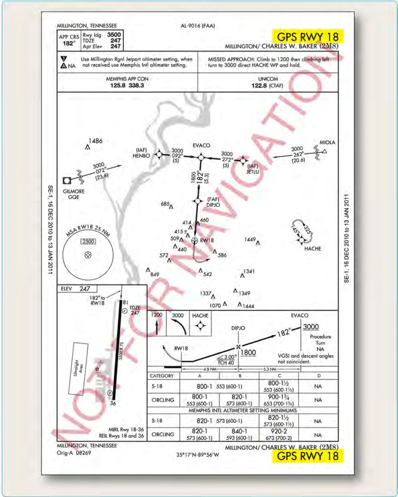
Figure 4-38. Traditional GPS approach overlay.
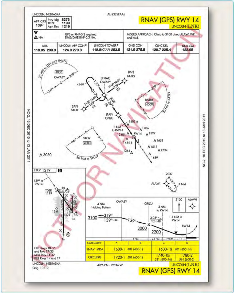
Figure 4-39. Lincoln Muni KLNK Lincoln, Nebraska, RNAV GPS RWY 14 approach.
approach, the final approach course is typically aligned to intersect the extended runway centerline 3,000 feet from the runway threshold, and the angle of convergence between the two does not exceed 30°. This type of VOR approach also includes a minimum of 300 feet of obstacle clearance in the final approach area. The final approach area criteria include a 2 NM wide primary area at the facility that expands to 6 NM wide at a distance of 10 NM from the facility. Additional approach criteria are established for courses that require a high altitude teardrop approach penetration.
When DME is included in the title of the VOR approach, operable DME must be installed in the aircraft in order to fly the approach from the FAF. The use of DME allows for an accurate determination of position without timing, which greatly increases situational awareness throughout the approach. Alexandria, Louisiana, is an excellent example of a VOR/DME approach in which the VOR is off the airport and a FAF is depicted. [Figure 4-53] In this case, the final approach course is a radial or straight-in final approach and is designed to intersect the runway centerline at the runway threshold with the angle of convergence not exceeding 30°.
The criteria for an arc final approach segment associated with a VOR/DME approach is based on the arc being beyond 7 NM and no farther than 30 NM from the VOR and depends on the angle of convergence between the runway centerline and the tangent of the arc. Obstacle clearance in the primary area, which is considered the area 4 NM on either side of the arc centerline, is guaranteed by at least 500 feet.
NDB Approach
Like the VOR approach, an NDB approach can be designed using facilities both on and off the airport, with or without a FAF, and with or without DME availability. At one time, it was commonplace for an instrument student to learn how to fly an NDB approach, but with the growing use of GPS, many pilots no longer use the NDB for instrument approaches. New RNAV approaches are also rapidly being constructed into airports that are served only by NDB. The long-term plan includes the gradual phase out of NDB facilities, and eventually, the NDB approach becomes nonexistent. Until that time, the NDB provides additional availability for instrument pilots into many smaller, remotely located airports.
The NDB Runway 35 approach at Carthage/Panola County Sharpe Field is an example of an NDB approach established with an on-airport NDB that does not incorporate a FAF. [Figure 4-54] In this case, a procedure turn or penetration turn is required to be a part of the approach design. For the NDB to be considered an on-airport facility, the facility must be located within one mile of any portion of the landing runway for straight-in approaches and within one mile of any portion of usable landing surface for circling approaches. The final approach segment of the approach is designed with a final approach area that is 2.5 NM wide at the facility and increases to 8 NM wide at 10 NM from the facility. Additionally, the final approach course and the extended runway centerline angle of convergence cannot exceed 30° for straight-in approaches. This type of NDB approach is afforded a minimum of 350 feet obstacle clearance.
When a FAF is established for an NDB approach, the approach design criteria changes. It also takes into account whether or not the NDB is located on or off the airport. Additionally, this type of approach can be made both moving toward or away from the NDB facility. The Tuscon Ryan Field, NDB/DME RWY 6 is an approach with a FAF using an on-airport NDB facility that also incorporates the use of DME. [Figure 4-55] In this case, the NDB has DME capabilities from the LOC approach system installed on the airport. While the alignment criteria and obstacle clearance remain the same as an NDB approach without a FAF, the final approach segment area criteria changes to an area that is 2.5 NM wide at the facility and increases to 5 NM wide, 15 NM from the NDB.
Radar Approaches
The two types of radar approaches available to pilots when operating in the NAS are precision approach radar (PAR) and airport surveillance radar (ASR). Radar approaches may be given to any aircraft at the pilot’s request. ATC may also offer radar approach options to aircraft in distress regardless of the weather conditions or as necessary to expedite traffic. Despite the control exercised by ATC in a radar approach environment, it remains the pilot’s responsibility to ensure the approach and landing minimums listed for the approach are appropriate for the existing weather conditions considering personal approach criteria certification and company OpSpecs.
Perhaps the greatest benefit of either type of radar approach is the ability to use radar to execute a no gyro approach. Assuming standard rate turns, ATC can indicate when to begin and end turns. If available, pilots should make use of this approach when the heading indicator has failed and partial panel instrument flying is required.
Information about radar approaches is published in tabular form in the front of the TPP booklet. PAR, ASR, and circling approach information including runway, DA, DH, or MDA, height above airport (HAA), HAT, ceiling, and visibility criteria
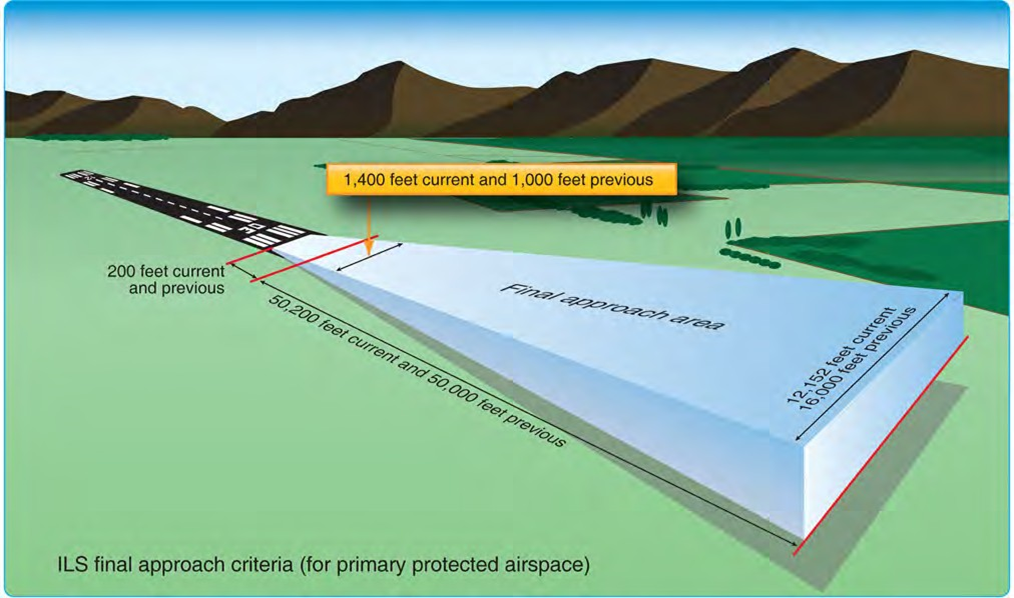
Figure 4-40. ILS final approach segment design criteria.
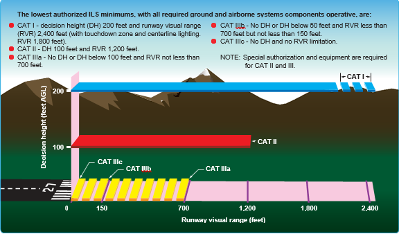
Figure 4-41. ILS approach categories.
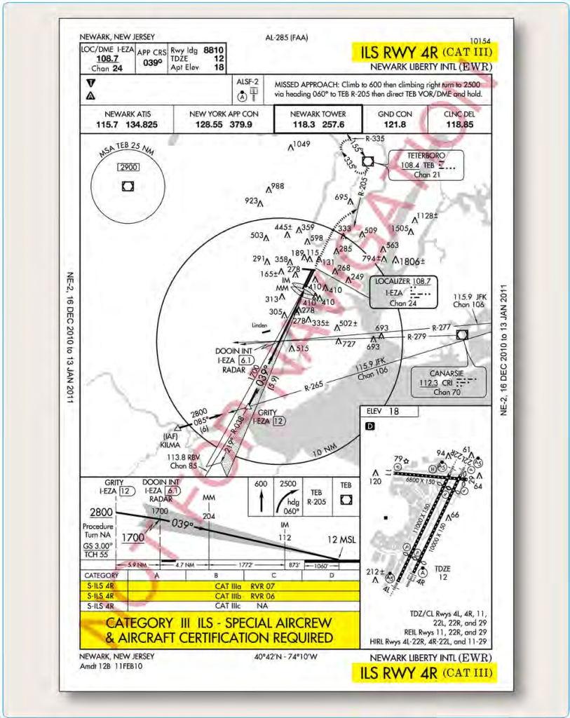
Figure 4-42. Category III approach procedure.
are outlined and listed by specific airport.
Regardless of the type of radar approach in use, ATC monitors aircraft position and issues specific heading and altitude information throughout the entire approach. Particularly, lost communications procedures should be briefed prior to execution to ensure pilots have a comprehensive understanding of ATC expectations if radio communication were lost. ATC also provides additional information concerning weather and missed approach instructions when beginning a radar approach. [Figure 4-56]
Precision Approach Radar (PAR)
PAR provides both vertical and lateral guidance, as well as range, much like an ILS, making it the most precise radar approach available. The radar approach, however, is not able to provide visual approach indications in the flight deck. This requires the flight crew to listen and comply with controller instructions. PAR approaches are rare, with most of the approaches used in a military setting; any opportunity to practice this type of approach is beneficial to any flight crew.
The final approach course of a PAR approach is normally aligned with the runway centerline, and the associated glideslope is typically no less than 2.5° and no more than 3°. Obstacle clearance for the final approach area is based on the particular established glideslope angle and the exact formula is outlined in FAA Order 8260.3. [Figure 4-57]
Airport Surveillance Radar (ASR)
ASR approaches are typically only approved when necessitated for an ATC operational requirement or in an unusual or emergency situation. This type of radar only provides heading and range information, although the controller can advise the pilot of the altitude where the aircraft should be based on the distance from the runway. An ASR approach procedure can be established at any radar
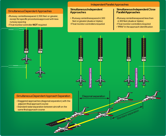
Figure 4-43. Classification of Simultaneous Parallel Approaches.
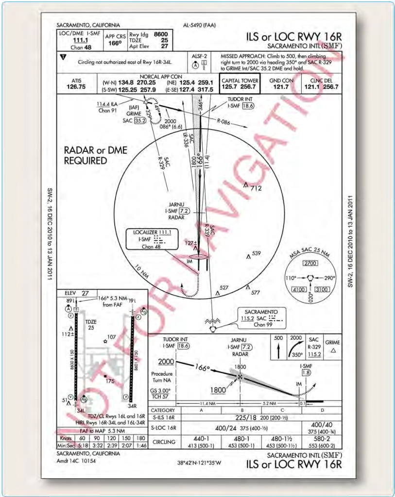
Figure 4-44. Sacramento International KSMF, Sacramento, California, ILS or LOC RWY 16L.
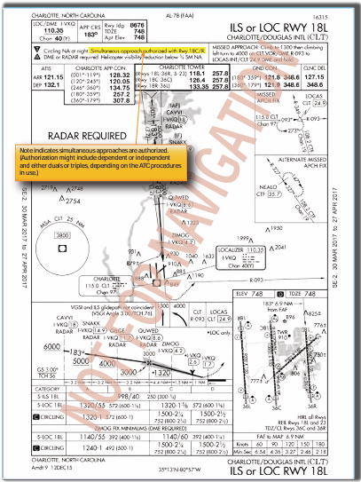
Figure 4-45. Charlotte Douglas International KCLT, Charlotte, North Carolina, ILS or LOC RWY 18L.
facility that has an antenna within 20 NM of the airport and meets the equipment requirements outlined in FAA Order 8200.1, U.S. Standard Flight Inspection Manual. ASR approaches are not authorized for use when Center Radar ARTS processing (CENRAP) procedures are in use due to diminished radar capability.
The final approach course for an ASR approach is aligned with the runway centerline for straight-in approaches and aligned with the center of the airport for circling approaches. Within the final approach area, the pilot is also guaranteed a minimum of 250 feet obstacle clearance. ASR descent gradients are designed to be relatively flat, with an optimal gradient of 150 feet per mile and never exceeding 300 feet per mile.
Localizer Approaches
As an approach system, the localizer is an extremely flexible approach aid that, due to its inherent design, provides many applications for a variety of needs in instrument flying. An ILS glideslope installation may be impossible due to surrounding terrain. The localizer is able to provide four separate types of non-precision approaches from one approach system:
- Localizer approach
- Localizer/DME approach
- Localizer back course approach
- Localizer-type directional aid (LDA)
Localizer and Localizer DME
The localizer approach system can provide both precision and non-precision approach capabilities to a pilot. As a part of the ILS system, the localizer provides horizontal guidance for a precision approach. Typically, when the localizer is discussed, it is thought of as a non-precision approach due to the fact that either it is the only approach system installed, or the glideslope is out of service on the ILS. In either case, the localizer provides a non-precision approach using a localizer transmitter installed at a specific airport. [Figure 4-58]
TERPS provides the same alignment criteria for a localizer approach as it does for the ILS, since it is essentially the
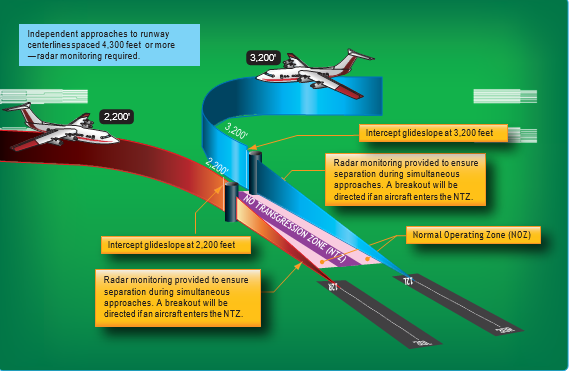
Figure 4-46. Simultaneous Independent Approach Example Using ILS Approaches.
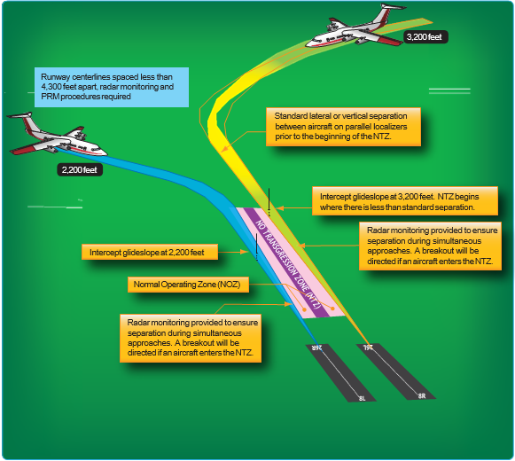
igure 4-47. Simultaneous independent close parallel approach example using ILS PRM approaches.
same approach without vertical guidance stemming from the glideslope. A localizer is always aligned within 3° of the runway, and it is afforded a minimum of 250 feet obstacle clearance in the final approach area. In the case of a localizer DME (LOC DME) approach, the localizer installation has a collocated DME installation that provides distance information required for the approach. [Figure 4-59]
Localizer Back Course
In cases where an ILS is installed, a back course may be available in conjunction with the localizer. Like the localizer, the back course does not offer a glideslope, but remember that the back course can project a false glideslope signal and the glideslope should be ignored. Reverse sensing occurs on the back course using standard VOR equipment.
With a horizontal situation indicator (HSI) system, reverse sensing is eliminated if it is set appropriately to the front course. [Figure 4-60]
Localizer-Type Directional Aid (LDA)
The LDA is of comparable use and accuracy to a localizer but is not part of a complete ILS. The LDA course usually provides a more precise approach course than the similar simplified directional facility (SDF) installation, which may have a course width of 6° or 12°.
The LDA is not aligned with the runway. Straight-in minimums may be published where alignment does not exceed 30° between the course and runway. Circling minimums only are published where this alignment exceeds 30°.
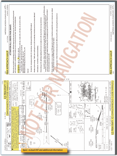
Figure 4-48. Example of Simultaneous close parallel instrument approach: Atlanta, Georgia, ILS PRM RWY 10 and AAUP.
A very limited number of LDA approaches also incorporate a glideslope. These are annotated in the plan view of the instrument approach chart with a note, “LDA/Glideslope.” These procedures fall under a newly defined category of approaches called Approach (Procedure) with Vertical Guidance (aviation) APVs. LDA minima for with and without glideslope is provided and annotated on the minima lines of the approach chart as S−LDA/GS and S−LDA. Because the final approach course is not aligned with the runway centerline, additional maneuvering is required compared to an ILS approach. [Figure 4-61]
Simplified Directional Facility (SDF)
The SDF provides a final approach course similar to that of the ILS localizer. It does not provide glideslope information. A clear understanding of the ILS localizer and the additional factors listed below completely describe the operational characteristics and use of the SDF. [Figure 4-62]
The approach techniques and procedures used in an SDF instrument approach are essentially the same as those employed in executing a standard localizer approach except the SDF course may not be aligned with the runway and the course may be wider, resulting in less precision. Like the LOC type approaches, the SDF is an alternative approach that may be installed at an airport for a variety of reasons, including terrain. The final approach is provided a minimum of 250 feet obstacle clearance for straight-in approaches while in the final approach area, which is an area defined for a 6° course: 1,000 feet at or abeam the runway threshold expanding to 19,228 feet (10 NM) from the threshold. The same final approach area for a 12° course is larger. This type of approach is also designed with a maximum descent gradient of 400 feet per NM, unless circling only minimums are authorized.
Figure 4-49. Example of Approach and AAUP used for Simultaneous Offset Instrument Approach Procedure.
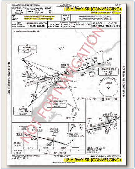
Figure 4-50. Converging approach criteria.
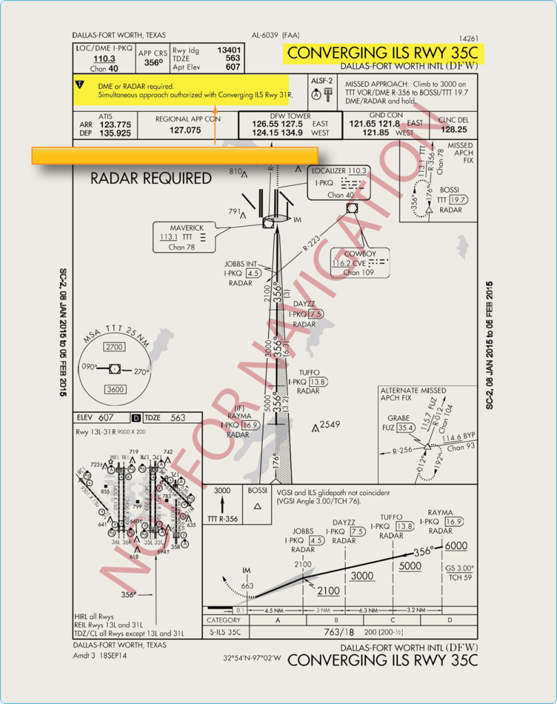
Figure 4-51. Dallas-Fort Worth KDFW, Dallas-Fort Worth, Texas, CONVERGING ILS RWY 35C.
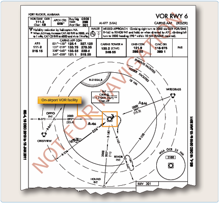
Figure 4-52. Fort Rucker, Alabama, KOZR VOR RWY 6.
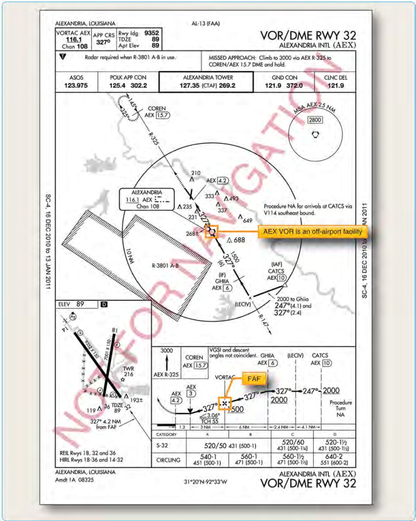
Figure 4-53. Alexandria International (AEX), Alexandria, Louisiana, KAEX VOR DME RWY 32.
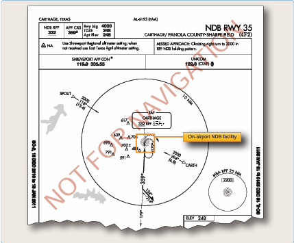
Figure 4-54. Carthage/Panola County-Sharpe Field, Carthage, Texas, (K4F2), NDB RWY 35.
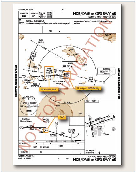
Figure 4-55. Tucson/Ryan Field, Tuscson, Arizona, (KRYN), NDB/DME or GPS RWY 6R.
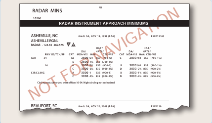
Figure 4-56. Asheville Regional KAVL, Asheville, North Carolina, radar instrument approach minimums.
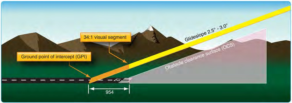
Figure 4-57. PAR final approach area criteria.
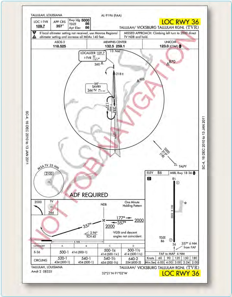
Figure 4-58. Vicksburg Tallulah Regional KTVR, Tallulah Vicksburg, Louisiana, LOC RWY 36.
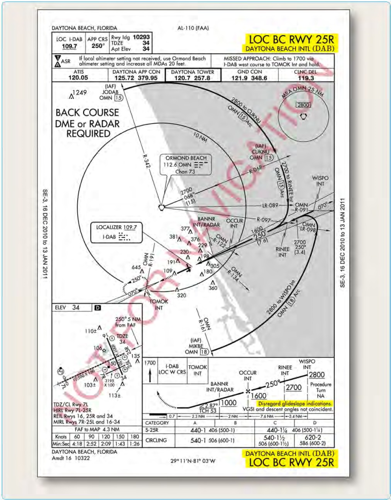
Figure 4-60. Dayton Beach International DAB, Dayton Beach, Florida, LOC BC RWY 25R.
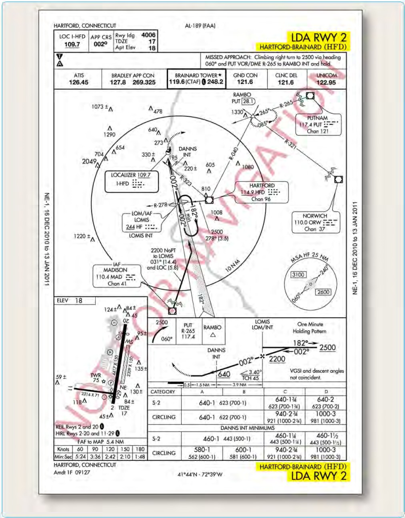
Figure 4-61. Hartford Brainard KHFD, Hartford, Connecticut, LDA RWY 2.
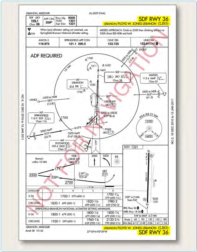
Figure 4-62. Lebanon Floyd W Jones, Lebanon, Missouri, SDF RWY 36.


