Introduction
Thousands of instrument flight rules (IFR) takeoffs and departures occur daily in the National Airspace System (NAS). In order to accommodate this volume of IFR traffic, air traffic control (ATC) must rely on pilots to use charted airport sketches and diagrams, as well as departure procedures (DPs) that include both standard instrument departures (SIDs) and obstacle departure procedures (ODPs). While many charted (and uncharted) departures are based on radar vectors, the bulk of IFR departures in the NAS require pilots to navigate out of the terminal environment to the en route phase.
IFR takeoffs and departures are fast-paced phases of flight, and pilots often are overloaded with critical flight information. While preparing for takeoff, pilots are busy requesting and receiving clearances, preparing their aircraft for departure, and taxiing to the active runway. During IFR conditions, they are doing this with minimal visibility, and they may be without constant radio communication if flying out of a non-towered airport. Historically, takeoff minimums for commercial operations have been successively reduced through a combination of improved signage, runway markings and lighting aids, and concentrated pilot training and qualifications. Today at major terminals, some commercial operators with appropriate equipment, pilot qualifications, and approved Operations Specifications (OpSpecs) may takeoff with visibility as low as 300 feet runway visual range (RVR). One of the consequences of takeoffs with reduced visibility is that pilots are challenged in maintaining situational awareness during taxi operations.
Surface Movement Safety
One of the biggest safety concerns in aviation is the surface movement accident. As a direct result, the FAA has rapidly expanded the information available to pilots, including the addition of taxiway and runway information in FAA publications, particularly the IFR U.S. Terminal Procedures Publication (TPP) booklets and the Chart Supplement (CS) volumes. The FAA has also implemented new procedures and created educational and awareness programs for pilots, ATC, and ground operators. By focusing resources to attack this problem head on, the FAA hopes to reduce and eventually eliminate surface movement accidents.
Airport Sketches and Diagrams
Airport sketches and diagrams provide pilots of all levels with graphical depictions of the airport layout. Aeronautical Information Services, formerly known as Aeronautical Products (AeroNav), provide an airport sketch on the lower left or right portion of every instrument approach chart. [Figure 1-1] This sketch depicts the runways, their length, width and slope, the touchdown zone elevation, the lighting system installed on the end of the runway, and taxiways. Graphical depictions of NOTAMS are also available for selected airports as well as for temporary flight restriction (TFRs) areas on the defense internet NOTAM service (DINS) website.
For select airports, typically those with heavy traffic or complex runway layouts, Aeronautical Information Services also prints an airport diagram. The diagram is located in the IFR TPP booklet following the instrument approach chart for a particular airport. It is a full page depiction of the airport that includes the same features of the airport sketch plus additional details, such as taxiway identifiers,
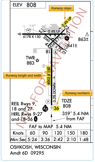
Figure 1-1. Airport diagram included on the Oshkosh, Wisconsin VOR RWY 9 Approach Chart as depicted in the IFR TPP.
airport latitude and longitude, and building identification. The airport diagrams are also available in the Airport/Facility Directory section of the Chart Supplement (CS) and on the Aeronautical Information Services’ website, located at www.aeronav.faa.gov. [Figure 1-2]
Chart Supplements (CS)
In recent years, the former Airport/Facility Directory (A/ FD) booklet was incorporated as a section in the Chart Supplement (CS). [Figure 2-14] The Chart Supplement (CS) is published by Aeronautical Information Services in regional booklets and online at: [https://www.faa.gov/ air_traffic/flight_info/aeronav/digital_products/dafd/] The online version is known as the digital Chart Supplement (d-CS). The d-CS and the CS are identical and provide textual and graphic information about all airports, both Visual Flight Rules (VFR) and IFR. The Airport/Facility Directory (A/FD) section of the CS includes runway length
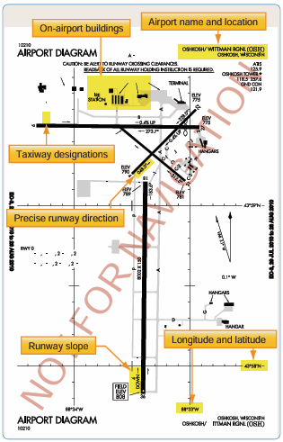
Figure 1-2. Airport diagram of Oshkosh, Wisconsin as depicted in the A/FD section of the CS.
and width, runway surface, load bearing capacity, runway slope, runway declared distances, airport services, and hazards, such as birds and reduced visibility. [Figure 1-3] Sketches of airports also are being added to aid VFR pilots in surface movement activities. In support of the FAA Runway Incursion Program, full page airport diagrams and “Hot Spot” locations are included in the A/FD section of the CS. These charts are the same as those published in the IFR TPP and are printed for airports with complex runway or taxiway layouts.
Surface Movement Guidance Control System (SMGCS)
The Surface Movement Guidance Control System (SMGCS) was developed to facilitate the safe movement of aircraft and vehicles at airports where scheduled air carriers were conducting authorized operations. Advisory Circular 120-57 was developed in 1992. In 2012, FAA Order 8000.94, Procedures for Establishing Airport Low-Visibility Operations and Approval of Low-Visibility Operations/Surface Movement Guidance and Control System Operations, was published to provide procedures for establishing Airport Low-Visibility Operations (LVO) and Surface Movement Guidance and Control Systems. It established the necessary FAA headquarters and operating services, roles, responsibilities, and activities for operations at 14 CFR Part 139 airports using RVRs of less than 1,200 feet for each runway. The order applies to all users of the system at all levels who are formally listed. The FAA requires the commissioning of an “FAA approved LVO/ SMGCS Operation” for all new Category III ILS supported runways. Since there are no regulatory takeoff minimums for 14 CFR Part 91 operations, the information provided by FAA AC 120-57 and FAA Order 8000.94 must be understood so that the general aviation pilot can understand LVO and SMGCS during day or night.
The SMGCS low visibility taxi plan includes the enhancement of taxiway and runway signs, markings, and lighting, as well as the creation of SMGCS visual aid diagrams. [Figure 1-4] The plan also clearly identifies taxi routes and their supporting facilities and equipment. Airport enhancements that are part of the SMGCS program include, but are not limited to:
- Controllable Stop bars lights—these consist of a row of red, unidirectional, in-pavement lights that can be controlled by ATC. They provide interactions with and aircraft that prevent runway incursions during takeoff operations. These are required for operations at less than 500 ft RVR.
- Non-Controllable Stop bars lights—these are red, unidirectinoal lights place at intersections where a restriction to movement is required. They must be in continuous operation at less than 500 ft RVR.
- Taxiway centerline lead-on lights—guide ground traffic under low visibility conditions and at night. These lights consist of alternating green/yellow in- pavement lights.
- Runway guard lights—either elevated or in- pavement, may be installed at all taxiways that provide access to an active runway. They consist of alternately flashing yellow lights. These lights are used to denote both the presence of an active runway and identify the location of a runway holding position marking.
- Geographic position markings—ATC verifies the position of aircraft and vehicles using geographic position markings. The markings can be used either as hold points or for position reporting. These checkpoints or “pink spots” are outlined with a black and white circle and designated with a number or a number and a letter.
- Clearance bar lights—three yellow in-pavement clearance bar lights used to denote holding positions for aircraft and vehicles. When used for hold points, they are co-located with geographic position markings.
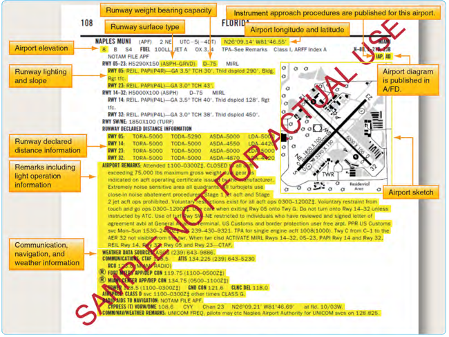
Figure 1-3. Excerpts from the Chart Supplement (Airport Facility Directory section) of Naples Muni, Naples, Florida.
Both flight and ground crews, Part 121 and 135 operators, are required to comply with SMGCS plans when implemented at their specific airport. All airport tenants are responsible for disseminating information to their employees and conducting training in low visibility operating procedures. Anyone operating in conjunction with the SMGCS plan must have a copy of the low visibility taxi route chart for their given airport as these charts outline the taxi routes and other detailed information concerning low visibility operations. These charts are available from private sources outside of the FAA. Government sources for SMGCS charts may be available in the future. Part 91 operators are expected to comply with the guidelines listed in AC 120-57, and should expect “Follow Me” service (when available) when low visibility operations are in use. Any SMGCS outage that would adversely affect operations at the airport is issued as a Notice to Airmen (NOTAM).
Advanced Surface Movement Guidance Control System (A-SMGCS)
With the increasing demand for airports to accommodate higher levels of aircraft movements, it is becoming more difficult for the existing infrastructure to safely handle greater capacities of traffic in all weather conditions. As a result, the FAA is implementing runway safety systems, such as Airport Surface Detection Equipment-Model X (ASDE-X) and Advanced Surface Movement Guidance and Control System (A-SMGCS) at various airports. The data that these systems use comes from surface movement radar and aircraft transponders. The combination of these data sources allows the systems to determine the position and identification of aircraft on the airport movement area and decreases the potential of collisions on airport runways and taxiways. Additional information concerning airport lighting, markings, and signs can be found in the Aeronautical Information Manual (AIM) and the Pilot’s Handbook of
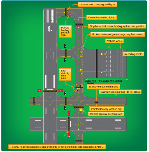
Figure 1-4. Key airport lighting and markings.
Aeronautical Knowledge, appendix 1, as well as on the FAA’s website at http://www.faa.gov/airports/runway_safety/.
Airport Signs, Lighting, and Markings
Flight crews use airport lighting, markings, and signs to help maintain situational awareness. These visual aids provide information concerning the aircraft’s location on the airport, the taxiway in use, and the runway entrance being used. Overlooking this information can lead to ground accidents that are entirely preventable. If you encounter unfamiliar markings or lighting, contact ATC for clarification and, if necessary, request progressive taxi instructions. Pilots are encouraged to notify the appropriate authorities of erroneous, misleading, or decaying signs or lighting that would contribute to the failure of safe ground operations.
Runway Incursions
On any given day, the NAS may handle almost 200,000 takeoffs and landings. Due to the complex nature of the airport environment and the intricacies of the network of people that make it operate efficiently, the FAA is constantly looking to maintain the high standard of safety that exists at airports today. Runway safety is one of its top priorities. The FAA defines a runway incursion as: “Any occurrence at an aerodrome involving the incorrect presence of an aircraft, vehicle, or person on the protected area of a surface designated for the landing and takeoff of aircraft.”
The four categories of runway incursions are listed below:
- Category A—a serious incident in which a collision was narrowly avoided.
- Category B—an incident in which separation decreases and there is a significant potential for collision that may result in a time critical corrective/ evasive response to avoid a collision.
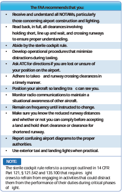
Figure 1-5. FAA recommendations for reducing runway incursions.
- Category C—an incident characterized by ample time and/or distance to avoid a collision.
- Category D—an incident that meets the definition of runway incursion, such as incorrect presence of a single vehicle/person/aircraft on the protected area of a surface designated for the landing and takeoff of aircraft but with no immediate safety consequences.
Figure 1-5 highlights several steps that reduce the chances of being involved in a runway incursion.
In addition to the SMGCS program, the FAA has implemented additional programs to reduce runway incursions and other surface movement issues. They identified runway hotspots, designed standardized taxi routes, and instituted the Runway Safety Program.
Runway Hotspots
ICAO defines runway hotspots as a location on an aerodrome movement area with a history or potential risk of collision or runway incursion and where heightened attention by pilots and drivers is necessary. Hotspots alert pilots to complex or potentially confusing taxiway geometry that could make surface navigation challenging. Whatever the reason, pilots need to be aware that these hazardous intersections exist, and they should be increasingly vigilant when approaching and taxiing through these intersections. These hotspots are depicted on some airport charts as circled areas. [Figure 1-6] The FAA Office of Runway Safety has links to the FAA regions that maintain a complete list of airports with runway hotspots at http://www.faa.gov/airports/runway_safety.
Standardized Taxi Routes
Standard taxi routes improve ground management at high- density airports, namely those that have airline service. At these airports, typical taxiway traffic patterns used to move aircraft between gate and runway are laid out and coded. The ATC specialist (ATCS) can reduce radio communication time and eliminate taxi instruction misinterpretation by simply clearing the pilot to taxi via a specific, named route. An example of this would be Los Angeles International Airport (KLAX), where North Route is used to transition to Runway 24L. [Figure 1-7] These routes are issued by ground control, and if unable to comply, pilots must advise ground control on initial contact. If for any reason the pilot becomes uncertain as to the correct taxi route, a request should be made for progressive taxi instructions. These step-by-step routing directions are also issued if the controller deems it necessary due to traffic, closed taxiways, airport construction, etc. It is the pilot’s responsibility to know if a particular airport has preplanned taxi routes, to be familiar with them, and to have the taxi descriptions in their possession. Specific information about airports that use coded taxiway routes is included in the Notices to Airmen Publication (NTAP).

Figure 1-6. Example of runway hot spots located at Long Beach/Daugherty Field Airport (KLGB).
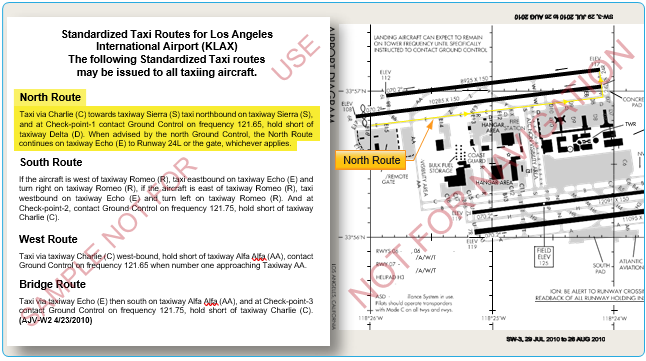
Figure 1-7. Los Angeles International Airport diagram, North Route, and standardized taxi route.
Taxi and Movement Operations Change
As of June 30, 2010, controllers are required to issue explicit instructions to cross or hold short of each runway that intersects a taxi route. Following is a summary of these procedural changes:
- “ Taxi to” is no longer used when issuing taxi instructions to an assigned takeoff runway.
- Instructions to cross a runway are issued one at a time. Instructions to cross multiple runways are not issued. An aircraft or vehicle must have crossed the previous runway before another runway crossing is issued. This applies to any runway, including inactive or closed runways.
- Never cross a runway hold marking without explicit ATC instructions. If in doubt, ask!
Reminder: You may not enter a runway unless you have been:
- Instructed to cross or taxi onto that specific runway;
- Cleared to take off from that runway; or
- Instructed to line up and wait on that specific runway.
For more information on the change, refer to FAA Order JO 7110.65, Air Traffic Control, which can be found at www. faa.gov.
Weather and the Departure Environment Takeoff Minimums
While mechanical failure is potentially hazardous during any phase of flight, a failure during takeoff under instrument conditions is extremely critical. In the event of an emergency, a decision must be made to either return to the departure airport or fly directly to a takeoff alternate. If the departure weather were below the landing minimums for the departure airport, the flight would be unable to return for landing, leaving few options and little time to reach a takeoff alternate.
In the early years of air transportation, landing minimums for commercial operators were usually lower than takeoff minimums. Therefore, it was possible that minimums allowed pilots to land at an airport but not depart from that airport. Additionally, all takeoff minimums once included ceiling, as well as visibility requirements. Today, takeoff minimums are typically lower than published landing minimums, and ceiling requirements are only included if it is necessary to see and avoid obstacles in the departure area.
The FAA establishes takeoff minimums for every airport that has published Standard Instrument Approaches. These minimums are used by commercially operated aircraft, namely Part 121 and Part 135 operators. At airports where minimums are not established, these same carriers are required to use FAA-designated standard minimums: 1 statute mile (SM) visibility for single- and twin-engine aircraft, and 1⁄2 SM for helicopters and aircraft with more than two engines.
Aircraft operating under 14 CFR Part 91 are not required to comply with established takeoff minimums. Legally, a zero/ zero departure may be made, but it is never advisable. If commercial pilots who fly passengers on a daily basis must comply with takeoff minimums, then good judgment and common sense would tell all instrument pilots to follow the established minimums as well.
Aeronautical Information Services charts list takeoff minimums only for the runways at airports that have other than standard minimums. These takeoff minimums are listed by airport in alphabetical order in the front of the TPP booklet. If an airport has non-standard takeoff minimums, a T (referred to by some as either the “triangle T” or “trouble T”) is placed in the notes sections of the instrument procedure chart. In the front of the TPP booklet, takeoff minimums are listed before the obstacle departure procedure. Some departure procedures allow a departure with standard minimums provided specific aircraft performance requirements are met. [Figure 1-8]
Takeoff Minimums for Commercial Operators
While Part 121 and Part 135 operators are the primary users of takeoff minimums, they may be able to use alternative takeoff minimums based on their individual OpSpecs. Through these OpSpecs, operators are authorized to depart with lower-than-standard minimums provided they have the necessary equipment and crew training.
Operations Specifications (OpSpecs)
Within the air transportation industry, there is a need to establish and administer safety standards to accommodate many variables. These variables include a wide range of aircraft, varied operator capabilities, the various situations requiring different types of air transportation, and the continual, rapid changes in aviation technology. It is impractical to address these variables through the promulgation of safety regulations for each and every type of air transport situation and the varying degrees of operator capabilities. Also, it is impractical to address the

Figure 1-8. Examples of non-standard takeoff minimums for Colorado Springs, Colorado.
rapidly changing aviation technology and environment through the regulatory process. Safety regulations would be extremely complex and unwieldy if all possible variations and situations were addressed by regulation. Instead, the safety standards established by regulation should usually have a broad application that allows varying acceptable methods of compliance. The OpSpecs provide an effective method for establishing safety standards that address a wide range of variables. In addition, OpSpecs can be adapted to a specific certificate holder or operator’s class and size of aircraft and type and kinds of operations. OpSpecs can be tailored to suit an individual certificate holder or operator’s needs.
Part 121 and Part 135 certificate holders have the ability, through the use of approved OpSpecs, to use lower-than• standard takeoff minimums. Depending on the equipment installed in a specific type of aircraft, the crew training, and the type of equipment installed at a particular airport, these operators can depart from appropriately equipped runways with as little as 300 feet RVR. Additionally, OpSpecs outline provisions for approach minimums, alternate airports, and weather services in Volume 3 of FAA Order 8900.1, Flight Standards Information Management System (FSIMS).
Figure 1-9. Examples of weather information of various flight information publications (FLIP).
Ceiling and Visibility Requirements
All takeoffs and departures have visibility minimums (some may have minimum ceiling requirements) incorporated into the procedure. There are a number of methods to report visibility and a variety of ways to distribute these reports, including automated weather observations. Flight crews should always check the weather, including ceiling and visibility information, prior to departure. Never launch an IFR flight without obtaining current visibility information immediately prior to departure. Further, when ceiling and visibility minimums are specified for IFR departure, both are applicable.
Weather reporting stations for specific airports across the country can be located by reviewing the CS. Weather sources along with their respective phone numbers and frequencies are listed by airport. Frequencies for weather sources, such as Automatic Terminal Information Service (ATIS), Digital Automatic Terminal Information Service (D-ATIS), Automated Weather Observing System (AWOS), Automated Surface Observing System (ASOS), and FAA Automated Flight Service Station (AFSS) are published on approach charts as well. [Figure 1-9]
Visibility
Visibility is the ability, as determined by atmospheric conditions and expressed in units of distance, to see and identify prominent unlighted objects by day and prominent lighted objects by night. Visibility is reported as statute miles, hundreds of feet, or meters.
Prevailing Visibility
Prevailing visibility is the greatest horizontal visibility equaled or exceeded throughout at least half the horizon circle, which need not necessarily be continuous. Prevailing visibility is reported in statute miles or fractions of miles.
Runway Visibility Value (RVV)
Runway visibility value is the visibility determined for a particular runway by a transmissometer. A meter provides
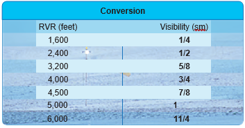
Figure 1-10. RVR conversion table.
continuous indication of the visibility (reported in statute miles or fractions of miles) for the runway. RVV is used in lieu of prevailing visibility in determining minimums for a particular runway.
Tower Visibility
Tower visibility is the prevailing visibility determined from the airport traffic control tower at locations that also report the surface visibility.
Runway Visual Range (RVR)
Runway visual range is an instrumentally derived value, based on standard calibrations, that represents the horizontal distance a pilot sees down the runway from the approach end. It is based on the sighting of either high intensity runway lights or on the visual contrast of other targets, whichever yields the greater visual range. RVR, in contrast to prevailing or runway visibility, is based on what a pilot in a moving aircraft should see looking down the runway. RVR is horizontal visual range, not slant visual range. RVR is reported in hundreds of feet, so the values must be converted to SM if the visibility in SM is not reported. [Figure 1-10] It is based on the measurement of a transmissometer made near the touchdown point of the instrument runway and is reported in hundreds of feet. RVR is used in lieu of RVV and/or prevailing visibility in determining minimums for a particular runway.
Types of RVR
The following are types of RVR that may be used:
- Touchdown RVR—the RVR visibility readout values obtained from RVR equipment serving the runway touchdown zone.
- Mid-RVR—the RVR readout values obtained from RVR equipment located near the runway midpoint .
- Rollout RVR—the RVR readout values obtained from RVR equipment located nearest the rollout end of the runway.
- Far End RVR—when four RVR visibility sensors (VS) are installed, the far end RVR VS is the touchdown RVR VS on the reciprocal runway. The far end sensor will serve as additional information.
RVR is the primary visibility measurement used by Part 121 and Part 135 operators with specific visibility reports and controlling values outlined in their respective OpSpecs. Under their OpSpecs agreements, the operator must have specific, current RVR reports, if available, to proceed with an instrument departure. OpSpecs also outline which visibility report is controlling in various departure scenarios.

Figure 1-11. AWSS installation at Driggs-Reed, Idaho.
Adequate Visual Reference
Another set of lower-than-standard takeoff minimums is available to Part 121 and Part 135 operations as outlined in their respective OpSpecs document. When certain types of visibility reports are unavailable or specific equipment is out of service, the flight can still depart the airport if the pilot can maintain adequate visual reference. An appropriate visual aid must be available to ensure the takeoff surface can be continuously identified, and directional control can be maintained throughout the takeoff run. Appropriate visual aids include high intensity runway lights, runway centerline lights, runway centerline markings, or other runway lighting and markings. With adequate visual references and appropriate OpSpec approval, commercial operators may take off with a visibility of 1600 RVR or ¼ SM.
Ceilings
Ceiling is the height above the earth’s surface of the lowest layer of clouds or obscuring phenomena that is reported as broken, overcast, or obscuration and not classified as thin or partial.
Automated Weather Systems
An automated weather system consists of any of the automated weather sensor platforms that collect weather data at airports and disseminate the weather information via radio and/or landline. The systems consist of the ASOS/ Automated Weather Sensor System (AWSS) and the AWOS.
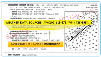
Figure 1-12. CS entry for an AWOS station.
These systems are installed and maintained at airports across the United States by both government (FAA and National Weather Service (NWS)) and private entities. They are relatively inexpensive to operate because they require no outside observer, and they provide invaluable weather information for airports without operating control towers. [Figure 1-11]
AWOS and ASOS/AWSS offer a wide variety of capabilities and progressively broader weather reports. Automated systems typically transmit weather every one to two minutes so the most up-to-date weather information is constantly broadcast. Basic AWOS includes only altimeter setting, wind speed, wind direction, temperature, and dew point information. More advanced systems, such as the ASOS/AWSS and AWOS-3, are able to provide additional information, such as wind speed, wind gust, wind direction, variable wind direction, temperature, dew point, altimeter setting, and density altitude. ASOS/AWSS stations providing service levels A or B also report RVR. The specific type of equipment found at a given facility is listed in the CS. [Figure 1-12]
The use of the aforementioned visibility reports and weather services are not limited for Part 91 operators. Part 121 and 135 operators are bound by their individual OpSpecs documents and are required to use weather reports that come from the NWS or other approved sources. While every operator’s specifications are individually tailored, most operators are required to use ATIS, RVR reports, and selected reports from automated weather stations. All reports coming from an AWOS-3 station are usable for Part 121 and Part 135 operators. Each type of automated station has different levels of approval as outlined in individual OpSpecs. Ceiling and visibility reports given by the tower with the departure information are always considered official weather, and RVR reports are typically the controlling visibility reference.
Automatic Terminal Information Service (ATIS)
ATIS is another valuable tool for gaining weather information. ATIS is available at most airports that have an operating control tower, which means the reports on the ATIS frequency are only available during the regular hours of tower operation. At some airports that operate part-time towers, ASOS/AWSS information is broadcast over the ATIS frequency when the tower is closed. This service is available only at those airports that have both an ASOS/ AWSS on the field and an ATIS-ASOS/AWSS interface switch installed in the tower.
Each ATIS report includes crucial information about runways and instrument approaches in use, specific outages, and current weather conditions including visibility. Visibility is reported in statute miles and may be omitted if the visibility is greater than five miles. ATIS weather information comes from a variety of sources depending on the particular airport and the equipment installed there. The reported weather may come from a manual weather observer, weather instruments located in the tower, or from automated weather stations. This information, no matter the origin, must be from NWS approved weather sources for it to be used in the ATIS report.
Digital Automatic Terminal Information Service (D-ATIS)
The digital ATIS (D-ATIS) is an alternative method of receiving ATIS reports. The service provides text messages to aircraft, airlines, and other users outside the standard reception range of conventional ATIS via landline and data link communications to the flight deck. Aircraft equipped with data link services are capable of receiving ATIS information over their Aircraft Communications Addressing and Reporting System (ACARS) unit. This allows the pilots to read and print out the ATIS report inside the aircraft, thereby increasing report accuracy and decreasing pilot workload. Also, the service provides a computer-synthesized voice message that can be transmitted to all aircraft within range of existing transmitters. The Terminal Data Link System (TDLS) D-ATIS application uses weather inputs from local automated weather sources or manually entered meteorological data together with preprogrammed menus to provide standard information to users. Airports with D-ATIS capability are listed in the CS.
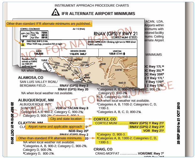
Figure 1-13. Examples of IFR alternate minimums.
It is important to remember that ATIS information is updated hourly and anytime a significant change in the weather occurs. As a result, the information is not the most current report available. Prior to departing the airport, you need to get the latest weather information from the tower. ASOS/AWSS and AWOS also provide a source of current weather, but their information should not be substituted for weather reports from the tower.
IFR Alternate Requirements
On Aeronautical Information Services charts, standard alternate minimums are not published. If the airport has other than standard alternate minimums, they are listed in the front of the approach chart booklet. The presence of a triangle with an on the approach chart indicates the listing of alternate minimums should be consulted. Airports that do not qualify for use as an alternate airport are designated with an N/A. [Figure 1-13]
The requirement for an alternate depends on the aircraft category, equipment installed, approach navigational aid (NAVAID), and forecast weather. For example, airports with only a global positioning system (GPS) approach procedure cannot be used as an alternate by TSO-C129 or C196 users unless certain requirements are met (see AIM) even though the “N/A” has been removed from the approach chart. For select area navigation (RNAV) GPS and GPS approach procedures, the “N/A” is being removed so they may be used as an alternate by aircraft equipped with an approach-approved Wide Area Augmentation System (WAAS) receiver complaying with (TSO-C145 or C146) or TSO-C129 or C196 meeitng certain requirements (see AIM). Because GPS is not authorized as a substitute means of navigation guidance when conducting a conventional approach at an alternate airport, if the approach procedure requires either distance measuring equipment (DME) or automatic direction finder (ADF), the aircraft must be equipped with the appropriate DME or ADF avionics in order to use the approach as an alternate.
For aircraft other than helicopters, 14 CFR Part 91 requirements, an alternate airport must be listed on IFR flight plans if the forecast weather at the destination airport, for at least one hour before and for one hour after the estimated time of arrival (ETA), the ceiling is less than 2,000 feet above the airport elevation, and the visibility is less than 3 SM. One way to remember the rules for determining the necessity of filing an alternate is the “1, 2, 3 Rule.”For helicopters, similar alternate filing requirements in 14 CFR Part 91 apply. An alternate must be listed on an IFR flight plan if at the ETA and for one hour after the ETA, the ceiling is at least 1,000 feet above the airport elevation, or at least 400 feet above the lowest applicable approach minima, whichever is higher, and the visibility is at least 2 SM.
Not all airports can be used as alternate airports. An airport may not be qualified for alternate use if the airport NAVAID is unmonitored, or if it does not have weather reporting capabilities. For an airport to be used as an alternate, the forecast weather at that airport must meet certain qualifications at the ETA. For aircraft other than helicopters, standard alternate minimums for a precision approach are a 600-foot ceiling and a 2 SM visibility. For a non-precision approach, the minimums are an 800-foot ceiling and a 2 SM visibility. Standard alternate minimums apply unless higher alternate minimums are listed for an airport. For helicopters, alternate weather minimums are a ceiling of 200 feet above the minimum for the approach to be flown, and visibility at least 1 SM but never less than the minimum visibility for the approach to be flown.
Alternate Minimums for Commercial Operators
IFR alternate minimums for Part 121 and Part 135 operators are very specific and have more stringent requirements than Part 91 operators.
Part 121 operators are required by their OpSpecs and 14 CFR Part 121, § 121.617 and 121.625 to have a takeoff alternate airport for their departure airport in addition to their airport of intended landing if the weather at the departure airport is below the landing minimums in the certificate holder’s OpSpecs for that airport. The alternate must be within two hours flying time for an aircraft with three or more engines with an engine out in normal cruise in still air. For two engine aircraft, the alternate must be within one hour. The airport of intended landing may be used in lieu of an alternate provided that it meets all the requirements. Domestic Part 121 operators must also file for alternate airports when the weather at their destination airport, from one hour before to one hour after their ETA, is forecast to be below a 2,000-foot ceiling and/or less than three miles visibility.
For alternate airports with at least one operational navigational facility that provides a straight-in non- precision approach, a straight-in precision approach, or a circling maneuver from an instrument approach procedure determine the ceiling and visibility by:
- Adding 400 feet to the authorized CAT I height above airport (HAA)/height above touchdown elevation (HAT) for ceiling.
- Adding one mile to the authorized CAT I visibility for visibility minimums.
This is one example of the criteria required for Part 121 operators when calculating minimums. Part 135 operators are also subject to their own specific rules regarding the selection and use of alternate minimums as outlined in their OpSpecs and 14 CFR Part 135, § 135.219 through 135.225, which are similar to those used by Part 121 operators with additional considerations.
Commercial operators typically use dispatchers to plan flights, including selecting and filing alternate airports. The dispatcher considers aircraft performance, aircraft equipment and its condition, and route of flight when choosing alternates. In the event changes need to be made to the flight plan en route due to deteriorating weather, the dispatcher maintains contact with the flight crew and reroutes their flight as necessary. Therefore, it is the pilot’s responsibility to execute the flight as planned by the dispatcher. To aid in the planning of alternates, dispatchers have a list of airports that are approved as alternates so they can quickly determine which airports should be used for a particular flight. Dispatchers also use flight planning software that plans routes including alternates for the flight. This type of software is tailored for individual operators and includes their normal flight paths and approved airports. Flight planning software and services are provided through private sources. Though the pilot is the final authority for the flight and ultimately has full responsibility, the dispatcher is responsible for creating flight plans that are accurate and comply with the CFRs. Alternate minimum criteria are only used as planning tools to ensure the pilot in command and dispatcher are thinking ahead to the approach phase of flight. In the event the flight would actually need to divert to an alternate, the published approach minimums or lower-than-standard minimums must be used as addressed in OpSpecs documents.
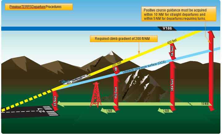
igure 1-14. Previous TERPS departure procedures.
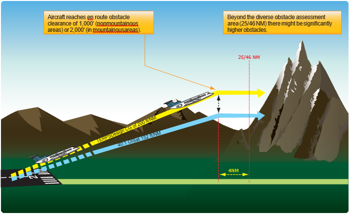
Figure 1-15. Diverse Departure Obstacle Assessment to 25/46 NM.
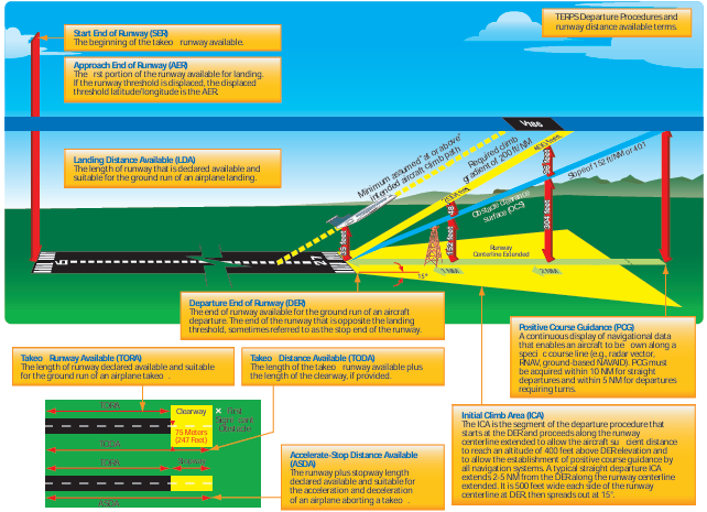
Figure 1-16. New TERPS departure procedures.
Departure Procedures
Instrument departure procedures are preplanned IFR procedures that provide obstruction clearance from the terminal area to the appropriate en route structure. Primarily, these procedures are designed to provide obstacle protection for departing aircraft. There are two types of Departure Procedures (DPs):
- Obstacle Departure Procedures (ODPs) and
- Standard Instrument Departures (SIDs).
When an instrument approach is initially developed for an airport, the need for an ODP is assessed. If an aircraft may turn in any direction from a runway within the limits of the assessment area and remain clear of obstacles that runway passes what is called a diverse departure assessment, and no ODP is published. A diverse departure assessment ensures that a prescribed, expanding amount of required obstacle clearance (ROC) is achieved during the climb-out until the aircraft can obtain a minimum 1,000 feet ROC in non-mountainous areas or a minimum 2,000 feet ROC in mountainous areas. Unless specified otherwise, required obstacle clearance for all departures, including diverse, is based on the pilot crossing the departure end of the runway (DER) at least 35 feet above the DER elevation, climbing to 400 feet above the DER elevation before making the initial turn, and maintaining a minimum climb gradient of 200 ft/ NM, unless required to level off by a crossing restriction, until the minimum IFR altitude is reached. Following ODP assessment, a SID may still be established for the purposes of ATC flow management, system enhancement, or noise abatement.
Design Criteria
The design of a departure procedure is based on FAA Order 8260.3, United States Standard for Terminal Instrument Procedures (TERPS), which is a living document that is updated frequently. Departure design criterion begins with the assumption of an initial climb of 200 ft/NM after crossing the DER at a height of at least 35 feet. [Figure 1-14] The aircraft climb path assumption provides a minimum of 35 feet of additional obstacle clearance above the required obstacle clearance (ROC), from the DER outward, to absorb variations ranging from the distance of the static source to the landing gear, to differences in establishing the minimum 200 ft/NM climb gradient, etc. The ROC is the planned separation between the obstacle clearance surface (OCS) and the required climb gradient of 200 ft/NM. The ROC value is zero at the DER elevation and increases along the departure route until the ROC value appropriate for en route flight is achieved. The appropriate ROC value for en route operations is typically achieved about 25 NM for 1,000 feet of ROC in non-mountainous areas, and 46 NM for 2,000 feet of ROC in mountainous areas.
If taking off from a runway using a diverse departure (a runway without a published ODP), beyond these distances the pilot is responsible for obstacle clearance if not operating on a published route, and if below the MEA or MOCA of a published route, or below an ATC-assigned altitude. [Figure 1-15]
Recent changes in TERPS criteria make the OCS lower and more restrictive. [Figure 1-16] However, there are many departures today that were evaluated under the old criteria that allowed some obstacle surfaces to be as high as 35 feet at the DER. [Figure 1-14] Since there is no way for the pilot to determine whether the departure was evaluated using the previous or current criteria, and until all departures have been evaluated using the current criteria, pilots need to be very familiar with the departure environment and associated obstacles, especially if crossing the DER at less than 35 feet.
All departure procedures are initially assessed for obstacle clearance based on a 40:1 Obstacle Clearance Surface (OCS). If no obstacles penetrate this 40:1 OCS, the standard 200 ft/NM climb gradient provides a minimum of 48 ft/NM of clearance above objects that do not penetrate the slope. The departure design must also include the acquisition of positive course guidance (PCG), typically within 5 to 10 NM of the DER for straight departures. Even when aircraft performance greatly exceeds the minimum climb gradient, the published departure routing must always be flown.
Airports publish the declared distances in the A/FD section of the CS. These include takeoff runway available (TORA), takeoff distance available (TODA), accelerate-stop distance available (ASDA), and landing distance available (LDA). These distances are calculated by adding to the full length of paved runway any applicable clearway or stop-way and subtracting from that sum the sections of the runway unsuitable for satisfying the required takeoff run, takeoff, accelerate/stop, or landing distance as shown in Figure 1-16.
Optimally, the 40 to 1 slope would work for every departure design; however, due to terrain and manmade obstacles, it is often necessary to use alternative requirements to accomplish a safe, obstacle-free departure design. In such cases, the design of the departure may incorporate a climb gradient greater than 200 ft/NM, an increase in the standard takeoff minimums to allow the aircraft to“see and avoid” the obstacles, a standard climb of 200 ft/NM with a specified reduced takeoff length, or a combination of these options and a specific departure route.
If a departure route is specified, it must be flown in conjunction with the other options.
The obstacle environment may require a climb gradient greater than 200 ft/NM. In these cases, the ROC provided above obstacles is equivalent to 24 percent of the published climb gradient. The required climb gradient, for obstacle purposes on ODPs and SIDs, is obtained by using the formulas:
Standard Formula DoD Option*
CG = O – E CG = (48D + O) – E/D
0.76 D
O = obstacle mean sea level (MSL) elevation E = climb gradient starting MSL elevation
D = distance (NM) from DER to the obstacle
Examples:
2049 – 1221 = 351.44 (48 × 3.1 + 2049) – 1221 = 315.10
0.76 × 3.1 3.1
Round to 352 ft/NM Round to 316 ft/NM
*Military only
These formulas are published in FAA Order 8260.3 for calculating the required climb gradient to clear obstacles.
The following formula is used for calculating SID climb gradients for other than obstacles (i.e., ATC requirements):
CG = A – E
D
A = “climb to” altitude
E = climb gradient starting MSL elevation
D = distance (NM) from the beginning of the climb Example:
3000 – 1221 /5= 355.8 round to 356 ft/NM
Note: The climb gradient must be equal to or greater than the gradient required for obstacles along the route of flight. The published climb gradient, obstacle or otherwise, is
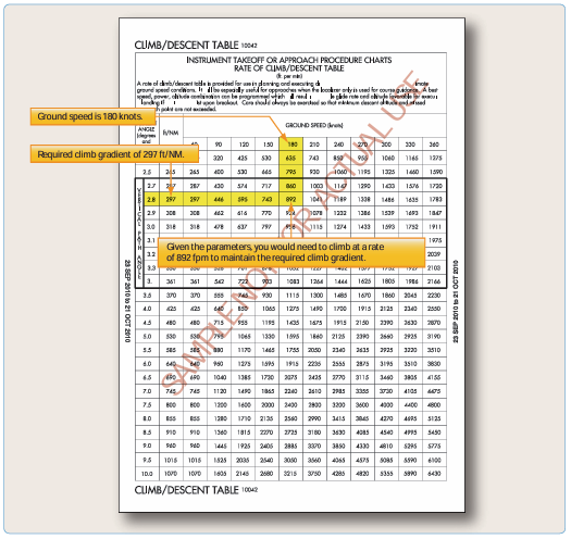
Figure 1-17. Rate of climb table.
treated as a plane which must not be penetrated from above until reaching the stated height or has reached the en route environment (e.g., above the MEA, MOCA). Departure design, including climb gradients, does not take into consideration the performance of the aircraft; it only considers obstacle protection for all aircraft. TERPS criteria assume the aircraft is operating with all available engines and systems fully functioning. Development of contingency procedures, required to cover the case of an engine failure, engine out procedures (EOPs) or other emergency in flight that may occur after liftoff, is the responsibility of the operator. When a climb gradient is required for a specific departure, it is vital that pilots fully understand the performance of their aircraft and determine if it can comply with the required climb. The standard climb of 200 ft/NM is not an issue for most aircraft. When an increased climb gradient is specified due to obstacle issues, it is important to calculate aircraft performance, particularly when flying out of airports at higher altitudes on warm days. To aid in the calculations, the front matter of every TPP booklet contains a rate of climb table that relates specific climb gradients and typical groundspeeds. [Figure 1-17].
Low, Close-In Obstacles
Obstacles that are located within 1 NM of the DER and penetrate the 40:1 OCS are referred to as “low, close-in obstacles”and are also included in the TPP. These obstacles
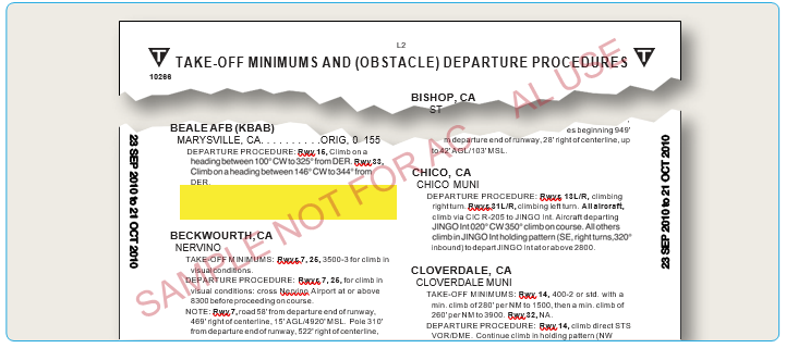
Figure 1-18. Examples of takeoff minimums obstacle clearance.

Figure 1-19. Part 25 turbine-powered, transport category airplane OEI actual (gross) takeoff flight path and OEI net takeoff flight path.
are less than 200 feet above the DER elevation, within 1 NM of the runway end, and do not require increased takeoff minimums. The standard ROC to clear these obstacles would require a climb gradient greater than 200 ft/NM for a very short distance, only until the aircraft was 200 feet above the DER. To eliminate publishing an excessive climb gradient, the obstacle above ground level (AGL)/ MSL height and location relative to the DER is noted in the Takeoff Minimums and (Obstacle) Departure Procedures section of a given TPP booklet. The purpose of this note is to identify the obstacle and alert the pilot to the height and location of the obstacle so they can be avoided. This can be accomplished in a variety of ways:
- The pilot may be able to see the obstruction and maneuver around the obstacle(s) if necessary;
- Early liftoff/climb performance may allow the aircraft to cross well above the obstacle(s);
- If the obstacle(s) cannot be visually acquired during departure, preflight planning should take into account what turns or other maneuver(s) may be necessary immediately after takeoff to avoid the obstruction(s).
These obstacles are especially critical to aircraft that do not lift off until close to the DER or which climb at the minimum rate. [Figure 1-18]
One-Engine-Inoperative (OEI) Takeoff Obstacle Clearance Requirements
Large and turbine-powered, multiengine transport category airplanes and commuter category airplanes operated under Part 121 or Part 135 have additional takeoff obstacle clearance requirements beyond the scope of the IFR departure procedure requirements addressed by TERPS.
Part 25 transport category and Part 23 commuter category airplane certification rules define the one-engine• inoperative (OEI) takeoff flight path, which is normally constructed from a series of segments beginning from 35 feet above the runway surface at the end of the OEI takeoff distance and ending at a minimum height of 1,500 feet above the runway elevation. However, the OEI net takeoff flight path assessment may continue above 1,500 feet if necessary to ensure obstacle clearance.
The actual, or gross, OEI flight path represents the vertical OEI climb profile that the aircraft has been demonstrated capable of achieving using takeoff procedures developed for line operations based on the aircraft’s weight, configuration, and environmental conditions at the time of takeoff. The OEI net takeoff flight path represents the actual OEI takeoff flight path that has been degraded by an amount specified by the certification rules to provide a safety margin for expected variations under operational conditions. Subpart I of Part 121 and Part 135 require that the OEI net takeoff flight path be at least 35 feet above obstacles that are located within the prescribed lateral distance either side of the flight path The actual obstacle clearance capability, under optimum conditions after experiencing an engine failure on takeoff, is equal to the difference between gross and net flight path, plus the additional 35 feet. [Figure 1-19]
Advisory Circular (AC) 120-91, Airport Obstacle Analysis, provides guidance and acceptable criteria for use in determining the safe lateral clearance from obstacles, when developing takeoff and initial climb out airport obstacle analyses and engine out obstacle avoidance procedures to comply with the intent of these regulatory requirements. Pilots departing an airport under IFR and operating under Part 121 or 135 are required by 14 CFR 91.175(f )(4) to use an engine-inoperative takeoff obstacle clearance or avoidance procedure that assures compliance with the obstacle clearance requirements (subpart I) of those rules. The assessment of OEI takeoff obstacle clearance is separate and independent of the IFR departure procedure and associated all-engines-operating climb gradient requirements. While the Part 91 operating rules governing large, commuter, and turbine-powered aircraft do not require the use of an OEI takeoff obstacle clearance or avoidance procedure, such use is encouraged for Part 91 operators of these aircraft.
Unlike TERPS, which assesses obstacle clearance beginning at the DER, the OEI net takeoff flight path obstacle assessment begins at the point where the aircraft reaches 35 feet above the runway at the end of the OEI takeoff distance. Therefore, the OEI net takeoff flight path assessment may begin before the DER allowing for the use of a portion of the runway for the OEI climb. The OEI net takeoff flight path obstacle clearance assessment must also account for clearance of the low, close-in obstacles that are noted on the IFR departure procedure, but are not necessarily cleared when complying with the TERPS-based IFR climb gradient.
The OEI net takeoff flight path is unique for each aircraft type and is assessed on each takeoff for the required obstacle clearance directly against those obstacles located beneath the OEI flight track and within the prescribed lateral distance from the flight path centerline. TERPS, on the other hand, provides a required climb gradient that represents a surface that the aircraft’s all-engines-operating climb profile must remain above throughout the IFR climb until reaching the en route environment. These two methods of assessing obstacle clearance are necessarily quite different. TERPS is used by the procedure designer
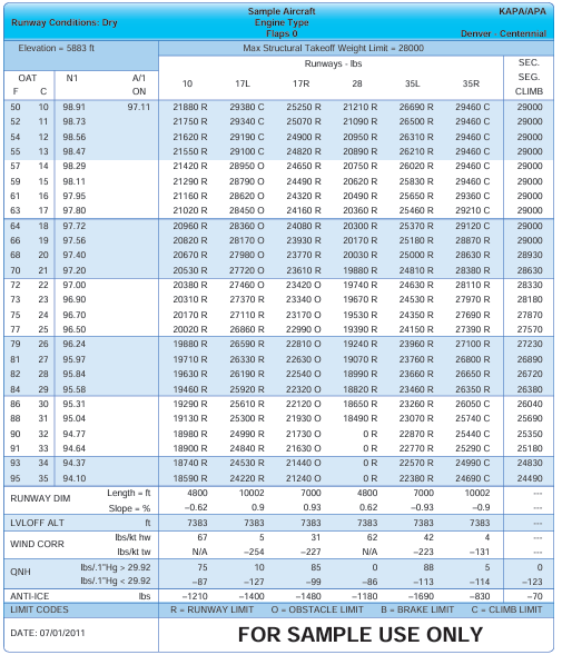
Figure 1-20. Airport/runway analysis example.
to determine a lateral path that is usable by a wide variety of aircraft types, and establishes a clearance plane that aircraft must be able to stay above to fly the procedure. A Part 25 transport category and Part 23 commuter category aircraft’s OEI takeoff flight path is established by or on behalf of the operator for a particular aircraft type and then limit weights are determined that assure clearance of any obstacles under that flight path (or within the prescribed lateral distance from the flight path centerline). It may be necessary for pilots and operators of these categories of aircraft to use the services of an aircraft performance engineer or airport/runway analysis service provider as means of compliance with the requirements of Part 121 subpart I, or Part 135 subpart I concerning OEI net takeoff flight obstacle clearance and takeoff field length requirements. [Figure 1-20] Airport/runway analysis involves the complex, usually computerized, computations of aircraft performance, using extensive airport/obstacle databases and terrain information. This yields maximum allowable takeoff and landing weights for particular aircraft/engine configurations for a specific airport, runway, and range of temperatures. The computations also consider flap settings, various aircraft characteristics, runway conditions, obstacle clearance, and weather conditions. Obstacle data also is available from these service providers for operators who desire to perform their own analysis using the OEI climb performance and flight path data furnished in the Airplane Flight Manual or when using an aircraft electronic performance program supplied by the manufacturer or other service provider. Airport/runway analysis is typically based on the assumption that the pilot will fly a straight-out departure following an engine failure on takeoff. However, when a straight-out departure is not practical or recommended, a special OEI turn procedure can be developed for each applicable runway. This OEI turn procedure may follow the path of a published IFR departure procedure or it may follow an independent path designed to avoid

Figure 1-21. Graphic ODP/booklet front matter.
otherwise onerous obstacles and thereby maximize the allowable takeoff weight and payload. Graphic depiction of the OEI procedure is often available to give the pilot a pictorial representation of the special OEI procedure. An engine failure during takeoff is a non-normal condition; therefore, the actions taken by the pilot including the use of an OEI turn procedure takes precedence over noise abatement, air traffic, SIDs, DPs, and other normal operating considerations.
It must be understood that the airport/runway analysis assesses obstacle clearance using the OEI net takeoff flight path data provided in the Airplane Flight Manual and the selected lateral obstacle assessment area. A takeoff weight limit provided on the analysis does not necessarily ensure compliance with the all-engines-operating climb gradient published on an IFR departure procedure even if the track of the OEI special procedure and the IFR departure procedure are identical.
Categories of Departure Procedures
There are two types of DPs: those developed to assist pilots in obstruction avoidance, known as ODPs, printed either textually or graphically, and those developed to communicate ATC clearances, SIDs, always printed graphically.
Obstacle Departure Procedures (ODPs)
The term ODP is used to define procedures that simply provide obstacle clearance. ODPs are only used for obstruction clearance and do not include ATC-related climb requirements. In fact, the primary emphasis of ODP design is to use the least restrictive route of flight to the en route structure or to facilitate a climb to an altitude that allows random (diverse) IFR flight, while attempting to accommodate typical departure routes.
An ODP must be developed when obstructions penetrate the 40:1 departure OCS, as described in FAA Order 8260.3. Only one ODP will be established for a particular runway. This is considered the default IFR departure procedure for a given runway and is intended for pilot awareness and use in the absence of ATC radar vectors or SID assignment. Text is not published to allow an option to use a SID or alternate maneuver assigned by ATC (e.g., “Climb heading 330 to 1200 before turning or use Manchester Departure” or “Turn right, climb direct ABC very high frequency (VHF) omnidirectional range (VOR) or as assigned by ATC.”). ODPs are textual in nature. However, due to the complex nature of some procedures, a visual presentation may be necessary for clarification and understanding. If the ODP is charted graphically, the chart itself includes the word “Obstacle” in parentheses in the title. Additionally, all newly-developed RNAV ODPs are issued in graphical form.
All ODPs are listed in the front of the Aeronautical Information Services approach chart booklets under the heading Takeoff Minimums and Obstacle Departure Procedures. Each procedure is listed in alphabetical order by city and state. The ODP listing in the front of the booklet includes a reference to the graphic chart located in the main body of the booklet if one exists. [Figure 1-21]
ODP Flight Planning Considerations
ODPs are not assigned by ATC unless absolutely necessary to achieve aircraft separation. It is the pilot’s responsibility to determine if there is an ODP published for that airport. If a Part 91 pilot is not given a clearance containing an ODP, SID, or radar vectors and an ODP exists, compliance with such a procedure is the pilot’s choice. A graphic ODP may also be filed in an instrument flight plan by using the computer code included in the procedure title. As a technique, the pilot may enter “will depart (airport) (runway) via textual ODP” in the remarks section of the flight plan. Providing this information to the controller clarifies the intentions of the pilot and helps prevent a potential pilot/controller misunderstanding. If the ODP is not included in the pilot’s clearance, the pilot should inform ATC when an ODP is used for departure from a runway so that ATC can ensure appropriate traffic separation.
During planning, pilots need to determine whether or not the departure airport has an ODP. Remember, an ODP can only be established at an airport that has instrument approach procedures (IAPs). An ODP may drastically affect the initial part of the flight plan. Pilots may have to depart at a higher than normal climb rate, or depart in a direction opposite the intended heading and maintain that for a period of time, any of which would require an alteration in the flight plan and initial headings. Considering the forecast weather, departure runways, and existing ODP, plan the flight route, climb performance, and fuel burn accordingly to compensate for the departure procedure.
Additionally, when close-in obstacles are noted in the Takeoff Minimums and (Obstacle) Departure Procedures section, it may require the pilot to take action to avoid these obstacles. Consideration must be given to decreased climb performance from an inoperative engine or to the amount of runway used for takeoff. Aircraft requiring a short takeoff roll on a long runway may have little concern. On the other hand, airplanes that use most of the available runway for takeoff may not have the standard ROC when climbing at the normal 200 ft/NM. Another factor to consider is the possibility of an
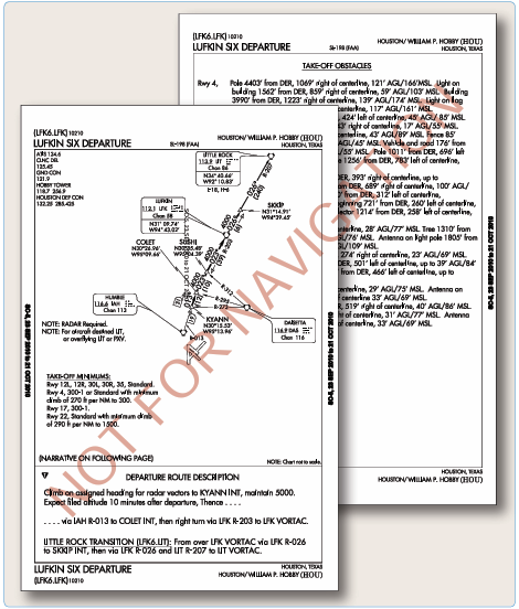
Figure 1-22. SID chart.
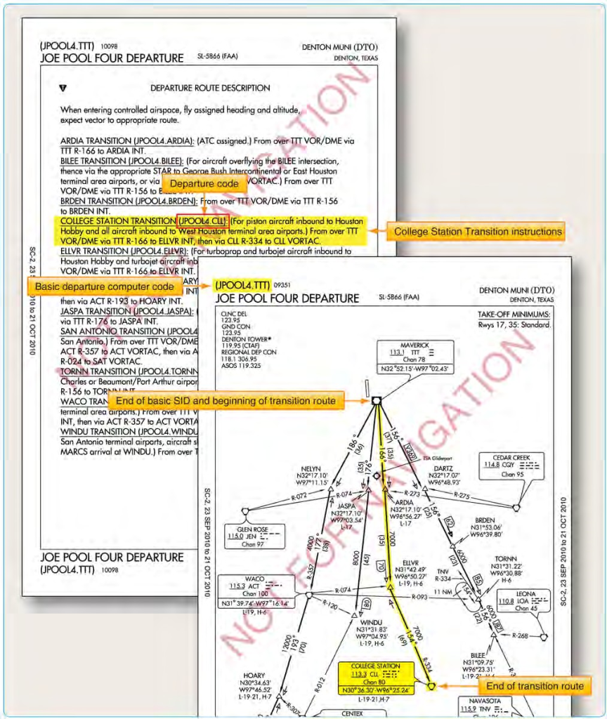
Figure 1-23. Transition routes as depicted on SID.
engine failure during takeoff and departure. During the preflight planning, use the aircraft performance charts to determine if the aircraft can still maintain the required climb performance. For high performance aircraft, an engine failure may not impact the ability to maintain the prescribed climb gradients. Aircraft that are performance limited may have diminished capability and may be unable to maintain altitude, let alone complete a climb to altitude. Based on the performance expectations for the aircraft, construct an emergency plan of action that includes emergency checklists and the actions to take to ensure safety in this situation.
Standard Instrument Departures (SIDs)
A SID is an ATC-requested and developed departure route, typically used in busy terminal areas. It is designed at the request of ATC in order to increase capacity of terminal airspace, effectively control the flow of traffic with minimal communication, and reduce environmental impact through noise abatement procedures.
While obstacle protection is always considered in SID routing, the primary goal is to reduce ATC/pilot workload while providing seamless transitions to the en route structure. ATC clearance must be received prior to flying a SID. SIDs also provide additional benefits to both the airspace capacity and the airspace users by reducing radio congestion, allowing more efficient airspace use, and simplifying departure clearances. All of the benefits combine to provide effective, efficient terminal operations, thereby increasing the overall capacity of the NAS.
If you cannot comply with a SID, if you do not possess the charted SID procedure, or if you simply do not wish to use SIDs, include the statement “NO SIDs” in the remarks section of your flight plan. Doing so notifies ATC that they cannot issue you a clearance containing a SID, but instead will clear you via your filed route to the extent possible, or via a Preferential Departure Route (PDR). It should be noted that SID usage not only decreases clearance delivery time, but also greatly simplifies your departure, easing you into the IFR structure at a desirable location and decreases your flight management load. While you are not required to depart using a SID, it may be more difficult to receive an “as filed” clearance when departing busy airports that frequently use SID routing.
SIDs are always charted graphically and are located in the TPP after the last approach chart for an airport. The SID may be one or two pages in length, depending on the size of the graphic and the amount of space required for the departure description. Each chart depicts the departure route, navigational fixes, transition routes, and required altitudes. The departure description outlines the particular procedure for each runway. [Figure 1-22]
Transition Routes
Charted transition routes allow pilots to transition from the end of the basic SID to a location in the en route structure. Typically, transition routes fan out in various directions from the end of the basic SID to allow pilots to choose the transition route that takes them in the direction of intended departure. A transition route includes a course, a minimum altitude, and distances between fixes on the route. When filing a SID for a specific transition route, include the transition in the flight plan, using the correct departure and transition code. ATC also assigns transition routes as a means of putting the flight on course to the destination. In any case, the pilot must receive an ATC clearance for the departure and the associated transition, and the clearance from ATC will include both the departure name and transition (e.g., Joe Pool Nine Departure, College Station Transition). [Figure 1-23]
The SID is designed to allow the pilot to provide his or her own navigation with minimal radio communication. This type of procedure usually contains an initial set of departure instructions followed by one or more transition routes. A SID may include an initial segment requiring radar vectors to help the flight join the procedure, but the majority of the navigation remains the pilot’s responsibility. [Figure 1-24]
A radar SID usually requires ATC to provide radar vectors from just after takeoff (ROC is based on a climb to 400 feet above the DER elevation before making the initial turn) until reaching the assigned route or a fix depicted on the SID chart. Radar SIDs do not include departure routes or transition routes because independent pilot navigation is not involved. The procedure sets forth an initial set of departure instructions that typically include an initial heading and altitude. ATC must have radar contact with the aircraft to be able to provide vectors. ATC expects you to immediately comply with radar vectors, and they expect you to notify them if you are unable to fulfill their request. ATC also expects you to make contact immediately if an instruction causes you to compromise safety due to obstructions or traffic. It is prudent to review radar SID charts prior to use because this type of procedure often includes nonstandard lost communication procedures. If you were to lose radio contact while being vectored by ATC, you would be expected to comply with the lost communication procedure as outlined on the chart, not necessarily those procedures outlined in the AIM. [Figure 1-25]
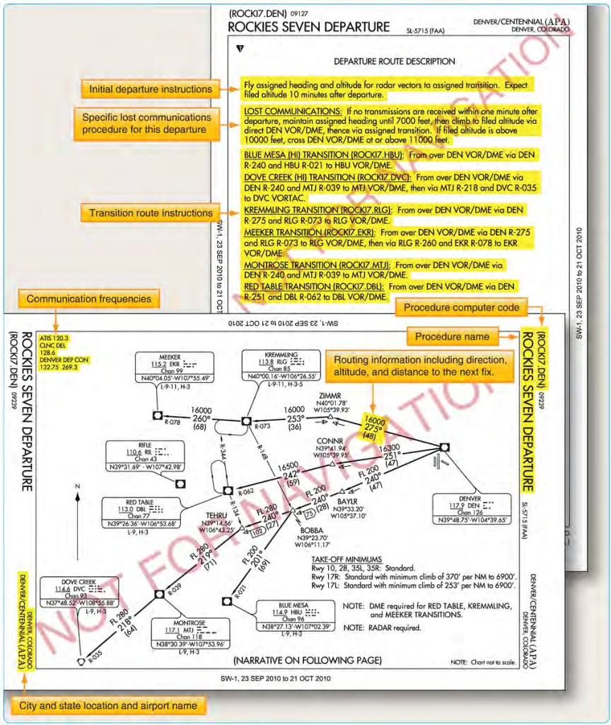
Figure 1-24. Example of a common SID at Denver, Colorado.
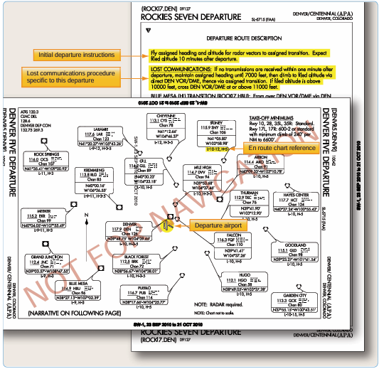
Figure 1-25. Example of a radar SID at Denver, Colorado.
SID Flight Planning Considerations
Take into consideration the departure paths included in the SIDs, and determine if you can use a standardized departure procedure. You have the opportunity to choose the SID that best suits your flight plan. During the flight planning phase, you can investigate each departure, and determine which procedure allows you to depart the airport in the direction of your intended flight. Also consider how a climb gradient to a specific altitude affects the climb time and fuel burn portions of the flight plan. Notes giving procedural requirements are listed on the graphic portion of a departure procedure, and they are mandatory in nature. [Figure 1-26] Mandatory procedural notes may include:
- Aircraft equipment requirements (DME, ADF, etc.)
- ATC equipment in operation (radar)
- Minimum climb requirements
- Restrictions for specific types of aircraft (turbojet only)
- Limited use to certain destinations
Cautionary statements may also be included on the procedure to notify you of specific activity, but these are strictly advisory. [Figure 1-26] If you are unable to comply with a specific requirement, you must not file the procedure as part of your flight plan. If ATC assigns you a SID, you may
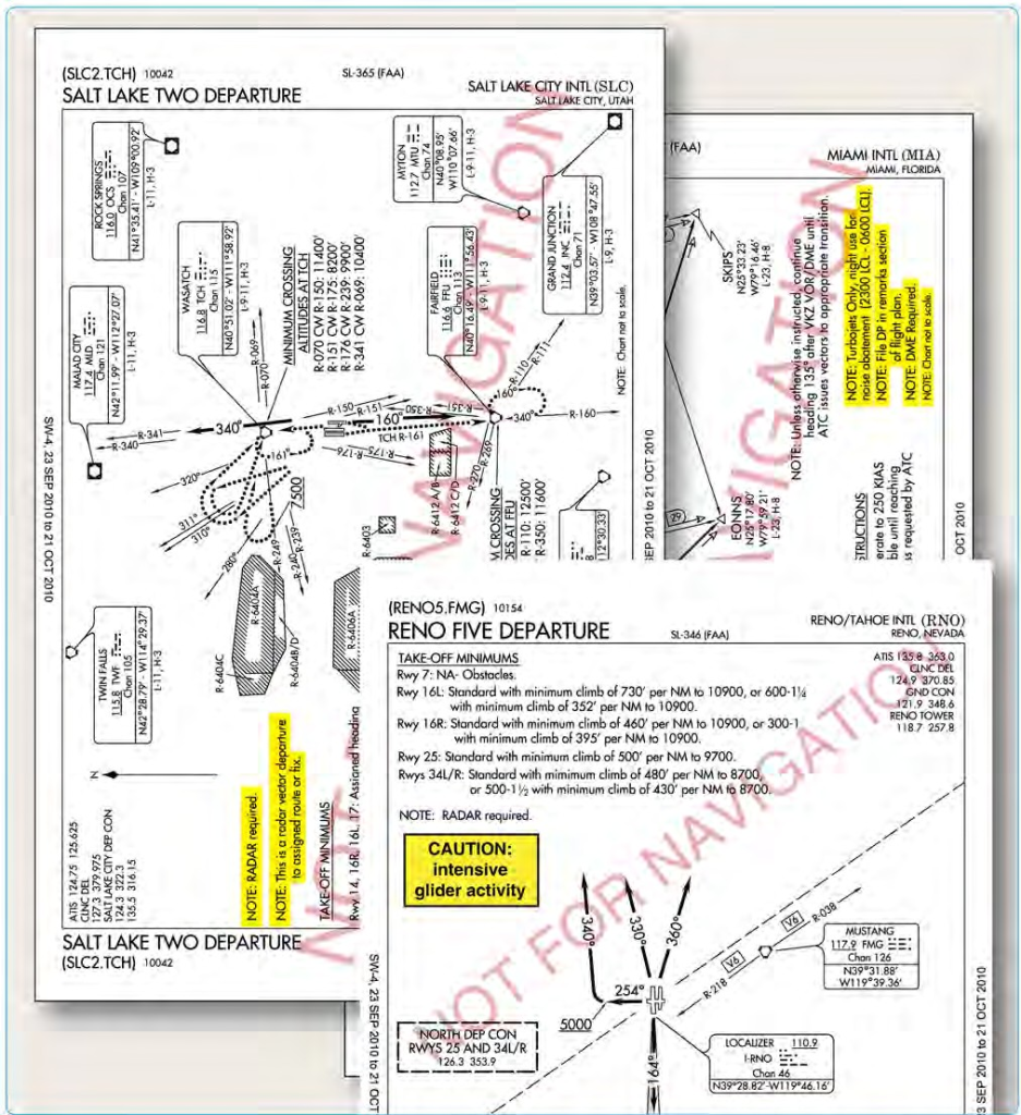
Figure 1-26. Departure procedure notes and cautionary statements.
need to quickly recalculate your all-engines-operating performance numbers. If you cannot comply with the climb gradient in the SID, you should not accept a clearance for that SID and furthermore, you must not accept the procedure if ATC assigns it.
A clearance for a SID which contains published altitude restrictions may be issued using the phraseology “climb via.” Climb via is an abbreviated clearance that requires compliance with the procedure lateral path, associated speed and altitude restrictions along the cleared route or procedure. Expanded procedures for “Climb via” can be found in the AIM.
ATC can assign SIDs or radar vectors as necessary for traffic management and convenience. To fly a SID, you must receive approval to do so in a clearance. In order to accept a clearance that includes a SID, you must have the charted SID procedure in your possession at the time of departure. It is your responsibility as pilot in command to accept or reject the issuance of a SID by ATC. You must accept or reject the clearance based on:
- The ability to comply with the required performance.
- The ability to navigate to the degree of accuracy required for the procedure.
- Possession of the charted SID procedure.
- Personal understanding of the SID in its entirety.
When you accept a clearance to depart using a SID or radar vectors, ATC is responsible for traffic separation. When departing with a SID, ATC expects you to fly the procedure as charted because the procedure design considers obstacle clearance. It is also expected that you will remain vigilant in scanning for traffic when departing in visual conditions. Furthermore, it is your responsibility to notify ATC if your clearance would endanger your safety or the safety of others. DPs are also categorized by equipment requirements as follows:
Non-RNAV DP—established for aircraft equipped with conventional avionics using ground-based NAVAIDs.These DPs may also be designed using dead reckoning navigation. Some flight management systems (FMS) are certified to fly a non-RNAV DP if the FMS unit accepts inputs from conventional avionics sources, such as DME, VOR, and localizer (LOC). These inputs include radio tuning and may be applied to a navigation solution one at a time or in combination. Some FMS provide for the detection and isolation of faulty navigation information.
- RNAV DP—established for aircraft equipped with RNAV avionics (e.g., GPS, VOR/DME, DME/DME). Automated vertical navigation is not required, and all RNAV procedures not requiring GPS must be annotated with the note: “RADAR REQUIRED.” Prior to using TSO-C129 GPS equipment for RNAV departures, approach receiver autonomous integrity monitoring (RAIM) availability should be checked for that location.
- Radar DP—radar may be used for navigation guidance for SID design. Radar SIDs are established when ATC has a need to vector aircraft on departure to a particular ATS Route, NAVAID, or fix. A fix may be a ground-based NAVAID, a waypoint, or defined by reference to one or more radio NAVAIDs. Not all fixes are waypoints since a fix could be a VOR or VOR/ DME, but all waypoints are fixes. Radar vectors may also be used to join conventional or RNAV navigation SIDs. SIDs requiring radar vectors must be annotated “RADAR REQUIRED.”
Area Navigation (RNAV) Departures
Historically, departure procedures were built around existing ground-based technology and were typically designed to accommodate lower traffic volumes. Often, departure and arrival routes use the same NAVAIDs creating
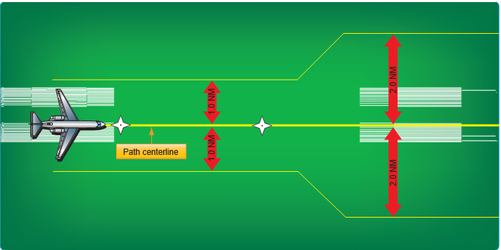
Figure 1-27. RNP departure levels.
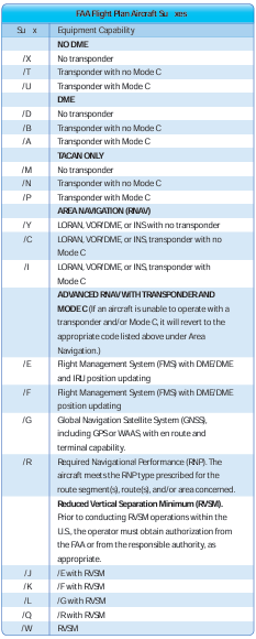
Figure 1-28. Flight plan equipment codes (continued).
interdependent, capacity diminishing routes. RNAV is a method of navigation that permits aircraft operation on any desired flight path within the coverage of ground- or spaced- based NAVAIDs or within the limits of the capability of self-contained aids or a combination of these. In the future, there will be an increased dependence on the use of RNAV in lieu of routes defined by ground-based NAVAIDs. As a part of the evolving RNAV structure, the FAA has developed departure procedures for pilots flying aircraft equipped with some type of RNAV technology. RNAV allows for the creation of new departure routes that are independent of present fixes and NAVAIDs. RNAV routing is part of the National Airspace Redesign (NAR) and is expected to reduce complexity and increase efficiency of terminal airspace.
When new RNAV departure procedures are designed, they will require minimal vectoring and communications between pilots and ATC. Usually, each departure procedure includes position, time, and altitude, which increase the ability to predict what the pilot will actually do. RNAV departure procedures have the ability to increase the capacity of terminal airspace by increasing on- time departures, airspace utilization, and improved predictability.
All public RNAV SIDs and graphic ODPs are RNAV 1. These procedures generally start with an initial RNAV or heading leg near the departure end runway. In addition, these procedures require system performance currently met by GPS, DME/DME/Inertial Reference Unit (IRU) RNAV systems that satisfy the criteria discussed in AC 90-100, U.S. Terminal and En Route Area Navigation (RNAV) Operations. RNAV departures are identifiable by the inclusion of the term RNAV in the title of the departure. From a required navigation performance (RNP) standpoint, RNAV departure routes are designed with 1 or 2 NM performance standards as listed below. This means you as the pilot and your aircraft equipment must be able to maintain the aircraft within 1 or 2 NM either side of route centerline. [Figure 1-27]
- RNAV 1 procedures require that the aircraft’s total system error remain bounded by ±1 NM for 95 percent of the total flight time.
- RNAV 2 requires a total system error of not more than 2 NM for 95 percent of the total flight time.
RNP is RNAV with on-board monitoring and alerting; RNP is also a statement of navigation performance necessary for operation within defined airspace. RNP 1 (in-lieu-of RNAV 1) is used when a DP that contains a constant radius to a fix (RF) leg or when surveillance (radar) monitoring is not desired for when DME/DME/IRU is used. These procedures are annotated with a standard note: “RNP 1.”
If unable to comply with the requirements of an RNAV or RNP procedure, pilots need to advise ATC as soon as possible. For example, “N1234, failure of GPS system, unable RNAV, request amended clearance.” Pilots are not authorized to fly a published RNAV or RNP procedure unless it is retrievable by the procedure name from the navigation database and conforms to the charted procedure. No other modification of database waypoints or creation of user- defined waypoints on published RNAV or RNP procedures is permitted, except to change altitude and/or airspeed waypoint constraints to comply with an ATC clearance/ instruction, or to insert a waypoint along the published route to assist in complying with an ATC instruction. For example, “Climb via the WILIT departure except cross 30 north of CHUCK at/ or above FL 210.” This is limited only to systems that allow along track waypoint construction.
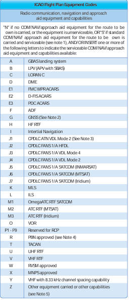
Pilots of aircraft utilizing DME/DME for primary navigation updating should ensure any required DME stations are in service as determined by NOTAM, ATIS, or ATC advisory. DME/DME navigation system updating may require specific DME facilities to meet performance standards. Based on DME availability evaluations at the time of publication, current DME coverage is not sufficient to support DME/DME RNAV operations everywhere without IRU augmentation or use of GPS. [Figure 1-28] DP chart notes may also include operational information for certain types of equipment, systems, and performance requirements, in addition to the type of RNAV departure procedure.
While operating on RNAV segments, pilots are encouraged to use the flight director in lateral navigation mode. RNAV terminal procedures may be amended by ATC issuing radar vectors and/or clearances direct to a waypoint. Pilots should avoid premature manual deletion of waypoints from their active “legs” page to allow for rejoining procedures. While operating on RNAV segments, pilots operating /R aircraft should adhere to any flight manual limitation or operating procedure required to maintain the RNP value specified for the procedure. In 2008, the FAA implemented the use of en route host automation ICAO flight plan (FP) processing for requesting assignment of RNAV SID, Standard Terminal Arrivals (STARs), or RNAV routes U.S. domestic airspace. This is part of a risk reduction strategy for introduction of the En Route Automation Modernization (ERAM) system in October 2008. ERAM also will use ICAO FP processing and as a result aircrews should be aware that as the FAA updates to ERAM the standard FAA flight plan equipment suffix codes will change to the ICAO flight plan equipment suffix codes.
For procedures requiring GPS and/or aircraft approvals requiring GPS, if the navigation system does not automatically alert the flight crew of a loss of GPS, aircraft operators must develop procedures to verify correct GPS IFR takeoffs and departures are fast-paced phases of flight, and pilots often are overloaded with critical flight information. While preparing for takeoff, pilots are busy requesting and receiving clearances, preparing their aircraft for departure, and taxiing to the active runway. During IFR conditions, they are doing this with minimal visibility, and they may be without constant radio communication if flying out of a non-towered airport. Historically, takeoff minimums for commercial operations have been successively reduced through a combination of improved signage, runway markings and lighting aids, and concentrated pilot training and qualifications. Today at major terminals, some commercial operators with appropriate equipment, pilot qualifications, and approved Operations Specifications (OpSpecs) may takeoff with visibility as low as 300 feet runway visual range (RVR). One of the consequences of takeoffs with reduced visibility is that pilots are challenged in maintaining situational awareness during taxi operations.
Surface Movement Safety
One of the biggest safety concerns in aviation is the surface movement accident. As a direct result, the FAA has rapidly expanded the information available to pilots, including the addition of taxiway and runway information in FAA publications, particularly the IFR U.S. Terminal Procedures Publication (TPP) booklets and the Chart Supplement (CS) volumes. The FAA has also implemented new procedures and created educational and awareness programs for pilots, ATC, and ground operators. By focusing resources to attack this problem head on, the FAA hopes to reduce and eventually eliminate surface movement accidents.
Airport Sketches and Diagrams
Airport sketches and diagrams provide pilots of all levels with graphical depictions of the airport layout. Aeronautical Information Services, formerly known as Aeronautical Products (AeroNav), provide an airport sketch on the lower left or right portion of every instrument approach chart. [Figure 1-1] This sketch depicts the runways, their length, width and slope, the touchdown zone elevation, the lighting system installed on the end of the runway, and taxiways. Graphical depictions of NOTAMS are also available for selected airports as well as for temporary flight restriction (TFRs) areas on the defense internet NOTAM service (DINS) website.
For select airports, typically those with heavy traffic or complex runway layouts, Aeronautical Information Services also prints an airport diagram. The diagram is located in the IFR TPP booklet following the instrument approach chart for a particular airport. It is a full page depiction of the airport that includes the same features of the airport sketch plus additional details, such as taxiway identifiers,
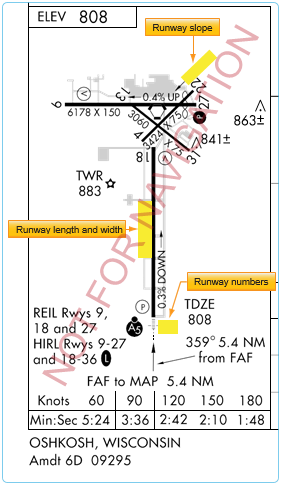
Figure 1-1. Airport diagram included on the Oshkosh, Wisconsin VOR RWY 9 Approach Chart as depicted in the IFR TPP.
airport latitude and longitude, and building identification. The airport diagrams are also available in the Airport/Facility Directory section of the Chart Supplement (CS) and on the Aeronautical Information Services’ website, located at www.aeronav.faa.gov. [Figure 1-2]
Chart Supplements (CS)
In recent years, the former Airport/Facility Directory (A/ FD) booklet was incorporated as a section in the Chart Supplement (CS). [Figure 2-14] The Chart Supplement (CS) is published by Aeronautical Information Services in regional booklets and online at: [https://www.faa.gov/ air_traffic/flight_info/aeronav/digital_products/dafd/] The online version is known as the digital Chart Supplement (d-CS). The d-CS and the CS are identical and provide textual and graphic information about all airports, both Visual Flight Rules (VFR) and IFR. The Airport/Facility Directory (A/FD) section of the CS includes runway length
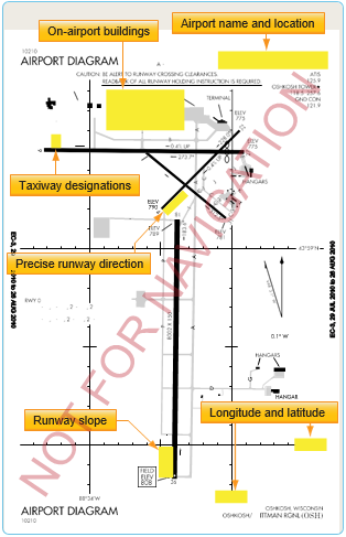
Figure 1-2. Airport diagram of Oshkosh, Wisconsin as depicted in the A/FD section of the CS.
and width, runway surface, load bearing capacity, runway slope, runway declared distances, airport services, and hazards, such as birds and reduced visibility. [Figure 1-3] Sketches of airports also are being added to aid VFR pilots in surface movement activities. In support of the FAA Runway Incursion Program, full page airport diagrams and “Hot Spot” locations are included in the A/FD section of the CS. These charts are the same as those published in the IFR TPP and are printed for airports with complex runway or taxiway layouts.
Surface Movement Guidance Control System (SMGCS)
The Surface Movement Guidance Control System (SMGCS) was developed to facilitate the safe movement of aircraft and vehicles at airports where scheduled air carriers were conducting authorized operations. Advisory Circular 120-57 was developed in 1992. In 2012, FAA Order 8000.94, Procedures for Establishing Airport Low-Visibility Operations and Approval of Low-Visibility Operations/Surface Movement Guidance and Control System Operations, was published to provide procedures for establishing Airport Low-Visibility Operations (LVO) and Surface Movement Guidance and Control Systems. It established the necessary FAA headquarters and operating services, roles, responsibilities, and activities for operations at 14 CFR Part 139 airports using RVRs of less than 1,200 feet for each runway. The order applies to all users of the system at all levels who are formally listed. The FAA requires the commissioning of an “FAA approved LVO/ SMGCS Operation” for all new Category III ILS supported runways. Since there are no regulatory takeoff minimums for 14 CFR Part 91 operations, the information provided by FAA AC 120-57 and FAA Order 8000.94 must be understood so that the general aviation pilot can understand LVO and SMGCS during day or night.
The SMGCS low visibility taxi plan includes the enhancement of taxiway and runway signs, markings, and lighting, as well as the creation of SMGCS visual aid diagrams. [Figure 1-4] The plan also clearly identifies taxi routes and their supporting facilities and equipment. Airport enhancements that are part of the SMGCS program include, but are not limited to:
- Controllable Stop bars lights—these consist of a row of red, unidirectional, in-pavement lights that can be controlled by ATC. They provide interactions with and aircraft that prevent runway incursions during takeoff operations. These are required for operations at less than 500 ft RVR.
- Non-Controllable Stop bars lights—these are red, unidirectinoal lights place at intersections where a restriction to movement is required. They must be in continuous operation at less than 500 ft RVR.
- Taxiway centerline lead-on lights—guide ground traffic under low visibility conditions and at night. These lights consist of alternating green/yellow in- pavement lights.
- Runway guard lights—either elevated or in- pavement, may be installed at all taxiways that provide access to an active runway. They consist of alternately flashing yellow lights. These lights are used to denote both the presence of an active runway and identify the location of a runway holding position marking.
- Geographic position markings—ATC verifies the position of aircraft and vehicles using geographic position markings. The markings can be used either as hold points or for position reporting. These checkpoints or “pink spots” are outlined with a black and white circle and designated with a number or a number and a letter.
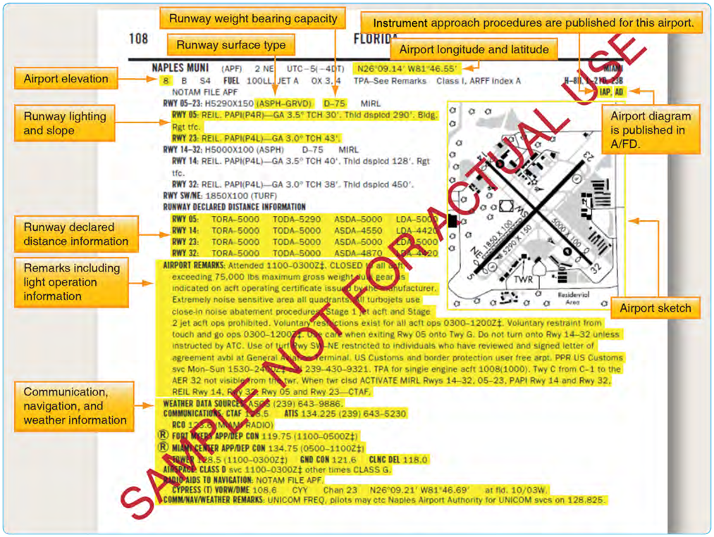
Figure 1-3. Excerpts from the Chart Supplement (Airport Facility Directory section) of Naples Muni, Naples, Florida.
- Clearance bar lights—three yellow in-pavement clearance bar lights used to denote holding positions for aircraft and vehicles. When used for hold points, they are co-located with geographic position markings.
Both flight and ground crews, Part 121 and 135 operators, are required to comply with SMGCS plans when implemented at their specific airport. All airport tenants are responsible for disseminating information to their employees and conducting training in low visibility operating procedures. Anyone operating in conjunction with the SMGCS plan must have a copy of the low visibility taxi route chart for their given airport as these charts outline the taxi routes and other detailed information concerning low visibility operations. These charts are available from private sources outside of the FAA. Government sources for SMGCS charts may be available in the future. Part 91 operators are expected to comply with the guidelines listed in AC 120-57, and should expect “Follow Me” service (when available) when low visibility operations are in use. Any SMGCS outage that would adversely affect operations at the airport is issued as a Notice to Airmen (NOTAM).
Advanced Surface Movement Guidance Control System (A-SMGCS)
With the increasing demand for airports to accommodate higher levels of aircraft movements, it is becoming more difficult for the existing infrastructure to safely handle greater capacities of traffic in all weather conditions. As a result, the FAA is implementing runway safety systems, such as Airport Surface Detection Equipment-Model X (ASDE-X) and Advanced Surface Movement Guidance and Control System (A-SMGCS) at various airports. The data that these systems use comes from surface movement radar and aircraft transponders. The combination of these data sources allows the systems to determine the position and identification of aircraft on the airport movement area and decreases the potential of collisions on airport runways and taxiways. Additional information concerning airport lighting, markings, and signs can be found in the Aeronautical Information Manual (AIM) and the Pilot’s Handbook of
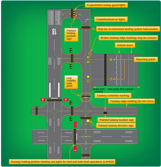
Figure 1-4. Key airport lighting and markings.
Aeronautical Knowledge, appendix 1, as well as on the FAA’s website at http://www.faa.gov/airports/runway_safety/.
Airport Signs, Lighting, and Markings
Flight crews use airport lighting, markings, and signs to help maintain situational awareness. These visual aids provide information concerning the aircraft’s location on the airport, the taxiway in use, and the runway entrance being used. Overlooking this information can lead to ground accidents that are entirely preventable. If you encounter unfamiliar markings or lighting, contact ATC for clarification and, if necessary, request progressive taxi instructions. Pilots are encouraged to notify the appropriate authorities of erroneous, misleading, or decaying signs or lighting that would contribute to the failure of safe ground operations.
Runway Incursions
On any given day, the NAS may handle almost 200,000 takeoffs and landings. Due to the complex nature of the airport environment and the intricacies of the network of people that make it operate efficiently, the FAA is constantly looking to maintain the high standard of safety that exists at airports today. Runway safety is one of its top priorities. The FAA defines a runway incursion as: “Any occurrence at an aerodrome involving the incorrect presence of an aircraft, vehicle, or person on the protected area of a surface designated for the landing and takeoff of aircraft.”
The four categories of runway incursions are listed below:
- Category A—a serious incident in which a collision was narrowly avoided.
- Category B—an incident in which separation decreases and there is a significant potential for collision that may result in a time critical corrective/ evasive response to avoid a collision.
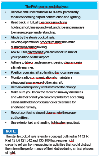
Figure 1-5. FAA recommendations for reducing runway incursions.
- Category C—an incident characterized by ample time and/or distance to avoid a collision.
- Category D—an incident that meets the definition of runway incursion, such as incorrect presence of a single vehicle/person/aircraft on the protected area of a surface designated for the landing and takeoff of aircraft but with no immediate safety consequences.
Figure 1-5 highlights several steps that reduce the chances of being involved in a runway incursion.
In addition to the SMGCS program, the FAA has implemented additional programs to reduce runway incursions and other surface movement issues. They identified runway hotspots, designed standardized taxi routes, and instituted the Runway Safety Program.
Runway Hotspots
ICAO defines runway hotspots as a location on an aerodrome movement area with a history or potential risk of collision or runway incursion and where heightened attention by pilots and drivers is necessary. Hotspots alert pilots to complex or potentially confusing taxiway geometry that could make surface navigation challenging. Whatever the reason, pilots need to be aware that these hazardous intersections exist, and they should be increasingly vigilant when approaching and taxiing through these intersections. These hotspots are depicted on some airport charts as circled areas. [Figure 1-6] The FAA Office of Runway Safety has links to the FAA regions that maintain a complete list of airports with runway hotspots at http://www.faa.gov/airports/runway_safety.
Standardized Taxi Routes
Standard taxi routes improve ground management at high- density airports, namely those that have airline service. At these airports, typical taxiway traffic patterns used to move aircraft between gate and runway are laid out and coded. The ATC specialist (ATCS) can reduce radio communication time and eliminate taxi instruction misinterpretation by simply clearing the pilot to taxi via a specific, named route. An example of this would be Los Angeles International Airport (KLAX), where North Route is used to transition to Runway 24L. [Figure 1-7] These routes are issued by ground control, and if unable to comply, pilots must advise ground control on initial contact. If for any reason the pilot becomes uncertain as to the correct taxi route, a request should be made for progressive taxi instructions. These step-by-step routing directions are also issued if the controller deems it necessary due to traffic, closed taxiways, airport construction, etc. It is the pilot’s responsibility to know if a particular airport has preplanned taxi routes, to be familiar with them, and to have the taxi descriptions in their possession. Specific information about airports that use coded taxiway routes is included in the Notices to Airmen Publication (NTAP).
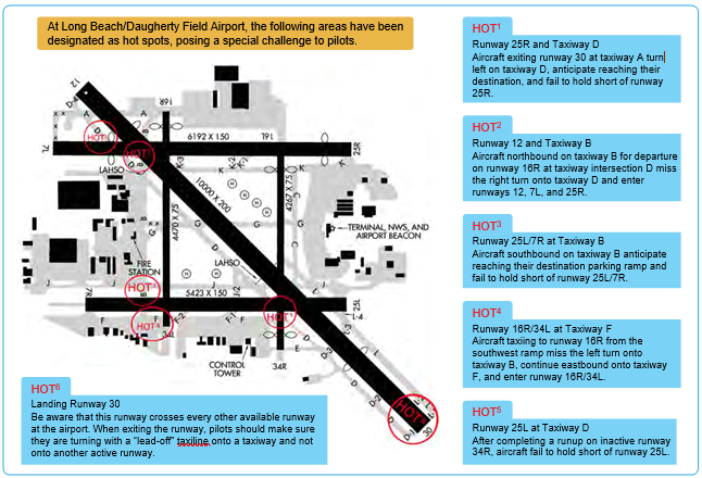
Figure 1-6. Example of runway hot spots located at Long Beach/Daugherty Field Airport (KLGB).
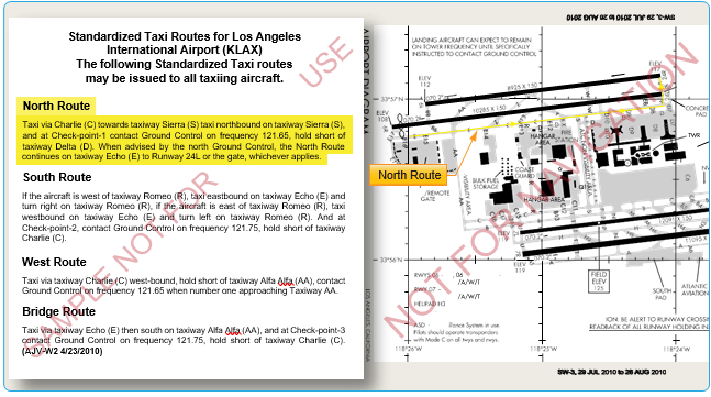
Figure 1-7. Los Angeles International Airport diagram, North Route, and standardized taxi route.
Taxi and Movement Operations Change
As of June 30, 2010, controllers are required to issue explicit instructions to cross or hold short of each runway that intersects a taxi route. Following is a summary of these procedural changes:
- “ Taxi to” is no longer used when issuing taxi instructions to an assigned takeoff runway.
- Instructions to cross a runway are issued one at a time. Instructions to cross multiple runways are not issued. An aircraft or vehicle must have crossed the previous runway before another runway crossing is issued. This applies to any runway, including inactive or closed runways.
- Never cross a runway hold marking without explicit ATC instructions. If in doubt, ask!
Reminder: You may not enter a runway unless you have been:
- Instructed to cross or taxi onto that specific runway;
- Cleared to take off from that runway; or
- Instructed to line up and wait on that specific runway.
For more information on the change, refer to FAA Order JO 7110.65, Air Traffic Control, which can be found at www. faa.gov.
Weather and the Departure Environment Takeoff Minimums
While mechanical failure is potentially hazardous during any phase of flight, a failure during takeoff under instrument conditions is extremely critical. In the event of an emergency, a decision must be made to either return to the departure airport or fly directly to a takeoff alternate. If the departure weather were below the landing minimums for the departure airport, the flight would be unable to return for landing, leaving few options and little time to reach a takeoff alternate.
In the early years of air transportation, landing minimums for commercial operators were usually lower than takeoff minimums. Therefore, it was possible that minimums allowed pilots to land at an airport but not depart from that airport. Additionally, all takeoff minimums once included ceiling, as well as visibility requirements. Today, takeoff minimums are typically lower than published landing minimums, and ceiling requirements are only included if it is necessary to see and avoid obstacles in the departure area.
The FAA establishes takeoff minimums for every airport that has published Standard Instrument Approaches. These minimums are used by commercially operated aircraft, namely Part 121 and Part 135 operators. At airports where minimums are not established, these same carriers are required to use FAA-designated standard minimums: 1 statute mile (SM) visibility for single- and twin-engine aircraft, and 1⁄2 SM for helicopters and aircraft with more than two engines.
Aircraft operating under 14 CFR Part 91 are not required to comply with established takeoff minimums. Legally, a zero/ zero departure may be made, but it is never advisable. If commercial pilots who fly passengers on a daily basis must comply with takeoff minimums, then good judgment and common sense would tell all instrument pilots to follow the established minimums as well.
Aeronautical Information Services charts list takeoff minimums only for the runways at airports that have other than standard minimums. These takeoff minimums are listed by airport in alphabetical order in the front of the TPP booklet. If an airport has non-standard takeoff minimums, a T (referred to by some as either the “triangle T” or “trouble T”) is placed in the notes sections of the instrument procedure chart. In the front of the TPP booklet, takeoff minimums are listed before the obstacle departure procedure. Some departure procedures allow a departure with standard minimums provided specific aircraft performance requirements are met. [Figure 1-8]
Takeoff Minimums for Commercial Operators
While Part 121 and Part 135 operators are the primary users of takeoff minimums, they may be able to use alternative takeoff minimums based on their individual OpSpecs. Through these OpSpecs, operators are authorized to depart with lower-than-standard minimums provided they have the necessary equipment and crew training.
Operations Specifications (OpSpecs)
Within the air transportation industry, there is a need to establish and administer safety standards to accommodate many variables. These variables include a wide range of aircraft, varied operator capabilities, the various situations requiring different types of air transportation, and the continual, rapid changes in aviation technology. It is impractical to address these variables through the promulgation of safety regulations for each and every type of air transport situation and the varying degrees of operator capabilities. Also, it is impractical to address the
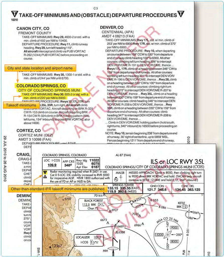
Figure 1-8. Examples of non-standard takeoff minimums for Colorado Springs, Colorado.
rapidly changing aviation technology and environment through the regulatory process. Safety regulations would be extremely complex and unwieldy if all possible variations and situations were addressed by regulation. Instead, the safety standards established by regulation should usually have a broad application that allows varying acceptable methods of compliance. The OpSpecs provide an effective method for establishing safety standards that address a wide range of variables. In addition, OpSpecs can be adapted to a specific certificate holder or operator’s class and size of aircraft and type and kinds of operations. OpSpecs can be tailored to suit an individual certificate holder or operator’s needs.
Part 121 and Part 135 certificate holders have the ability, through the use of approved OpSpecs, to use lower-than• standard takeoff minimums. Depending on the equipment installed in a specific type of aircraft, the crew training, and the type of equipment installed at a particular airport, these operators can depart from appropriately equipped runways with as little as 300 feet RVR. Additionally, OpSpecs outline provisions for approach minimums, alternate airports, and weather services in Volume 3 of FAA Order 8900.1, Flight Standards Information Management System (FSIMS).
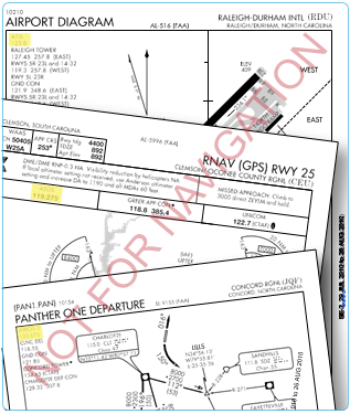
Figure 1-9. Examples of weather information of various flight information publications (FLIP).
Ceiling and Visibility Requirements
All takeoffs and departures have visibility minimums (some may have minimum ceiling requirements) incorporated into the procedure. There are a number of methods to report visibility and a variety of ways to distribute these reports, including automated weather observations. Flight crews should always check the weather, including ceiling and visibility information, prior to departure. Never launch an IFR flight without obtaining current visibility information immediately prior to departure. Further, when ceiling and visibility minimums are specified for IFR departure, both are applicable.
Weather reporting stations for specific airports across the country can be located by reviewing the CS. Weather sources along with their respective phone numbers and frequencies are listed by airport. Frequencies for weather sources, such as Automatic Terminal Information Service (ATIS), Digital Automatic Terminal Information Service (D-ATIS), Automated Weather Observing System (AWOS), Automated Surface Observing System (ASOS), and FAA Automated Flight Service Station (AFSS) are published on approach charts as well. [Figure 1-9]
Visibility
Visibility is the ability, as determined by atmospheric conditions and expressed in units of distance, to see and identify prominent unlighted objects by day and prominent lighted objects by night. Visibility is reported as statute miles, hundreds of feet, or meters.
Prevailing Visibility
Prevailing visibility is the greatest horizontal visibility equaled or exceeded throughout at least half the horizon circle, which need not necessarily be continuous. Prevailing visibility is reported in statute miles or fractions of miles.
Runway Visibility Value (RVV)
Runway visibility value is the visibility determined for a particular runway by a transmissometer. A meter provides
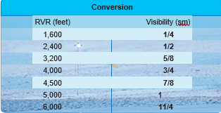
Figure 1-10. RVR conversion table.
continuous indication of the visibility (reported in statute miles or fractions of miles) for the runway. RVV is used in lieu of prevailing visibility in determining minimums for a particular runway.
Tower Visibility
Tower visibility is the prevailing visibility determined from the airport traffic control tower at locations that also report the surface visibility.
Runway Visual Range (RVR)
Runway visual range is an instrumentally derived value, based on standard calibrations, that represents the horizontal distance a pilot sees down the runway from the approach end. It is based on the sighting of either high intensity runway lights or on the visual contrast of other targets, whichever yields the greater visual range. RVR, in contrast to prevailing or runway visibility, is based on what a pilot in a moving aircraft should see looking down the runway. RVR is horizontal visual range, not slant visual range. RVR is reported in hundreds of feet, so the values must be converted to SM if the visibility in SM is not reported. [Figure 1-10] It is based on the measurement of a transmissometer made near the touchdown point of the instrument runway and is reported in hundreds of feet. RVR is used in lieu of RVV and/or prevailing visibility in determining minimums for a particular runway.
Types of RVR
The following are types of RVR that may be used:
- Touchdown RVR—the RVR visibility readout values obtained from RVR equipment serving the runway touchdown zone.
- Mid-RVR—the RVR readout values obtained from RVR equipment located near the runway midpoint .
- Rollout RVR—the RVR readout values obtained from RVR equipment located nearest the rollout end of the runway.
- Far End RVR—when four RVR visibility sensors (VS) are installed, the far end RVR VS is the touchdown RVR VS on the reciprocal runway. The far end sensor will serve as additional information.
RVR is the primary visibility measurement used by Part 121 and Part 135 operators with specific visibility reports and controlling values outlined in their respective OpSpecs. Under their OpSpecs agreements, the operator must have specific, current RVR reports, if available, to proceed with an instrument departure. OpSpecs also outline which visibility report is controlling in various departure scenarios.
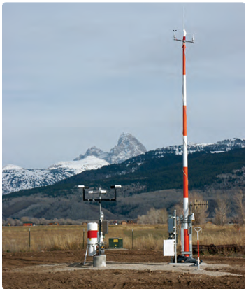
Figure 1-11. AWSS installation at Driggs-Reed, Idaho.
Adequate Visual Reference
Another set of lower-than-standard takeoff minimums is available to Part 121 and Part 135 operations as outlined in their respective OpSpecs document. When certain types of visibility reports are unavailable or specific equipment is out of service, the flight can still depart the airport if the pilot can maintain adequate visual reference. An appropriate visual aid must be available to ensure the takeoff surface can be continuously identified, and directional control can be maintained throughout the takeoff run. Appropriate visual aids include high intensity runway lights, runway centerline lights, runway centerline markings, or other runway lighting and markings. With adequate visual references and appropriate OpSpec approval, commercial operators may take off with a visibility of 1600 RVR or ¼ SM.
Ceilings
Ceiling is the height above the earth’s surface of the lowest layer of clouds or obscuring phenomena that is reported as broken, overcast, or obscuration and not classified as thin or partial.
Automated Weather Systems
An automated weather system consists of any of the automated weather sensor platforms that collect weather data at airports and disseminate the weather information via radio and/or landline. The systems consist of the ASOS/ Automated Weather Sensor System (AWSS) and the AWOS.
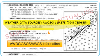
Figure 1-12. CS entry for an AWOS station.
These systems are installed and maintained at airports across the United States by both government (FAA and National Weather Service (NWS)) and private entities. They are relatively inexpensive to operate because they require no outside observer, and they provide invaluable weather information for airports without operating control towers. [Figure 1-11]
AWOS and ASOS/AWSS offer a wide variety of capabilities and progressively broader weather reports. Automated systems typically transmit weather every one to two minutes so the most up-to-date weather information is constantly broadcast. Basic AWOS includes only altimeter setting, wind speed, wind direction, temperature, and dew point information. More advanced systems, such as the ASOS/AWSS and AWOS-3, are able to provide additional information, such as wind speed, wind gust, wind direction, variable wind direction, temperature, dew point, altimeter setting, and density altitude. ASOS/AWSS stations providing service levels A or B also report RVR. The specific type of equipment found at a given facility is listed in the CS. [Figure 1-12] The use of the aforementioned visibility reports and weather services are not limited for Part 91 operators. Part 121 and 135 operators are bound by their individual OpSpecs documents and are required to use weather reports that come from the NWS or other approved sources. While every operator’s specifications are individually tailored, most operators are required to use ATIS, RVR reports, and selected reports from automated weather stations. All reports coming from an AWOS-3 station are usable for Part 121 and Part 135 operators. Each type of automated station has different levels of approval as outlined in individual OpSpecs. Ceiling and visibility reports given by the tower with the departure information are always considered official weather, and RVR reports are typically the controlling visibility reference.
Automatic Terminal Information Service (ATIS)
ATIS is another valuable tool for gaining weather information. ATIS is available at most airports that have an operating control tower, which means the reports on the ATIS frequency are only available during the regular hours of tower operation. At some airports that operate part-time towers, ASOS/AWSS information is broadcast over the ATIS frequency when the tower is closed. This service is available only at those airports that have both an ASOS/ AWSS on the field and an ATIS-ASOS/AWSS interface switch installed in the tower.
Each ATIS report includes crucial information about runways and instrument approaches in use, specific outages, and current weather conditions including visibility. Visibility is reported in statute miles and may be omitted if the visibility is greater than five miles. ATIS weather information comes from a variety of sources depending on the particular airport and the equipment installed there. The reported weather may come from a manual weather observer, weather instruments located in the tower, or from automated weather stations. This information, no matter the origin, must be from NWS approved weather sources for it to be used in the ATIS report.
Digital Automatic Terminal Information Service (D-ATIS)
The digital ATIS (D-ATIS) is an alternative method of receiving ATIS reports. The service provides text messages to aircraft, airlines, and other users outside the standard reception range of conventional ATIS via landline and data link communications to the flight deck. Aircraft equipped with data link services are capable of receiving ATIS information over their Aircraft Communications Addressing and Reporting System (ACARS) unit. This allows the pilots to read and print out the ATIS report inside the aircraft, thereby increasing report accuracy and decreasing pilot workload.
Also, the service provides a computer-synthesized voice message that can be transmitted to all aircraft within range of existing transmitters. The Terminal Data Link System (TDLS) D-ATIS application uses weather inputs from local automated weather sources or manually entered meteorological data together with preprogrammed menus to provide standard information to users. Airports with D-ATIS capability are listed in the CS.
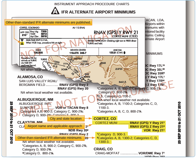
Figure 1-13. Examples of IFR alternate minimums.
It is important to remember that ATIS information is updated hourly and anytime a significant change in the weather occurs. As a result, the information is not the most current report available. Prior to departing the airport, you need to get the latest weather information from the tower. ASOS/AWSS and AWOS also provide a source of current weather, but their information should not be substituted for weather reports from the tower.
IFR Alternate Requirements
On Aeronautical Information Services charts, standard alternate minimums are not published. If the airport has other than standard alternate minimums, they are listed in the front of the approach chart booklet. The presence of a triangle with an on the approach chart indicates the listing of alternate minimums should be consulted. Airports that do not qualify for use as an alternate airport are designated with an N/A. [Figure 1-13]
The requirement for an alternate depends on the aircraft category, equipment installed, approach navigational aid (NAVAID), and forecast weather. For example, airports with only a global positioning system (GPS) approach procedure cannot be used as an alternate by TSO-C129 or C196 users unless certain requirements are met (see AIM) even though the “N/A” has been removed from the approach chart. For select area navigation (RNAV) GPS and GPS approach procedures, the “N/A” is being removed so they may be used as an alternate by aircraft equipped with an approach-approved Wide Area Augmentation System (WAAS) receiver complaying with (TSO-C145 or C146) or TSO-C129 or C196 meeitng certain requirements (see AIM). Because GPS is not authorized as a substitute means of navigation guidance when conducting a conventional approach at an alternate airport, if the approach procedure requires either distance measuring equipment (DME) or automatic direction finder (ADF), the aircraft must be equipped with the appropriate DME or ADF avionics in order to use the approach as an alternate.
For aircraft other than helicopters, 14 CFR Part 91 requirements, an alternate airport must be listed on IFR flight plans if the forecast weather at the destination airport, for at least one hour before and for one hour after the estimated time of arrival (ETA), the ceiling is less than 2,000 feet above the airport elevation, and the visibility is less than 3 SM. One way to remember the rules for determining the necessity of filing an alternate is the “1, 2, 3 Rule.”For helicopters, similar alternate filing requirements in 14 CFR Part 91 apply. An alternate must be listed on an IFR flight plan if at the ETA and for one hour after the ETA, the ceiling is at least 1,000 feet above the airport elevation, or at least 400 feet above the lowest applicable approach minima, whichever is higher, and the visibility is at least 2 SM.
Not all airports can be used as alternate airports. An airport may not be qualified for alternate use if the airport NAVAID is unmonitored, or if it does not have weather reporting capabilities. For an airport to be used as an alternate, the forecast weather at that airport must meet certain qualifications at the ETA. For aircraft other than helicopters, standard alternate minimums for a precision approach are a 600-foot ceiling and a 2 SM visibility. For a non-precision approach, the minimums are an 800-foot ceiling and a 2 SM visibility. Standard alternate minimums apply unless higher alternate minimums are listed for an airport. For helicopters, alternate weather minimums are a ceiling of 200 feet above the minimum for the approach to be flown, and visibility at least 1 SM but never less than the minimum visibility for the approach to be flown.
Alternate Minimums for Commercial Operators
IFR alternate minimums for Part 121 and Part 135 operators are very specific and have more stringent requirements than Part 91 operators.
Part 121 operators are required by their OpSpecs and 14 CFR Part 121, § 121.617 and 121.625 to have a takeoff alternate airport for their departure airport in addition to their airport of intended landing if the weather at the departure airport is below the landing minimums in the certificate holder’s OpSpecs for that airport. The alternate must be within two hours flying time for an aircraft with three or more engines with an engine out in normal cruise in still air. For two engine aircraft, the alternate must be within one hour. The airport of intended landing may be used in lieu of an alternate provided that it meets all the requirements. Domestic Part 121 operators must also file for alternate airports when the weather at their destination airport, from one hour before to one hour after their ETA, is forecast to be below a 2,000-foot ceiling and/or less than three miles visibility.
For alternate airports with at least one operational navigational facility that provides a straight-in non- precision approach, a straight-in precision approach, or a circling maneuver from an instrument approach procedure determine the ceiling and visibility by:
- Adding 400 feet to the authorized CAT I height above airport (HAA)/height above touchdown elevation (HAT) for ceiling.
- Adding one mile to the authorized CAT I visibility for visibility minimums.
This is one example of the criteria required for Part 121 operators when calculating minimums. Part 135 operators are also subject to their own specific rules regarding the selection and use of alternate minimums as outlined in their OpSpecs and 14 CFR Part 135, § 135.219 through 135.225, which are similar to those used by Part 121 operators with additional considerations.
Commercial operators typically use dispatchers to plan flights, including selecting and filing alternate airports. The dispatcher considers aircraft performance, aircraft equipment and its condition, and route of flight when choosing alternates. In the event changes need to be made to the flight plan en route due to deteriorating weather, the dispatcher maintains contact with the flight crew and reroutes their flight as necessary. Therefore, it is the pilot’s responsibility to execute the flight as planned by the dispatcher. To aid in the planning of alternates, dispatchers have a list of airports that are approved as alternates so they can quickly determine which airports should be used for a particular flight. Dispatchers also use flight planning software that plans routes including alternates for the flight. This type of software is tailored for individual operators and includes their normal flight paths and approved airports. Flight planning software and services are provided through private sources.
Though the pilot is the final authority for the flight and ultimately has full responsibility, the dispatcher is responsible for creating flight plans that are accurate and comply with the CFRs. Alternate minimum criteria are only used as planning tools to ensure the pilot in command and dispatcher are thinking ahead to the approach phase of flight. In the event the flight would actually need to divert to an alternate, the published approach minimums or lower-than-standard minimums must be used as addressed in OpSpecs documents.
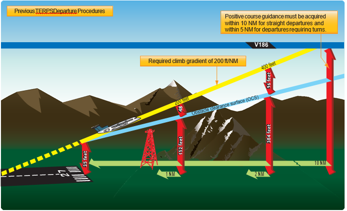
Figure 1-14. Previous TERPS departure procedures.
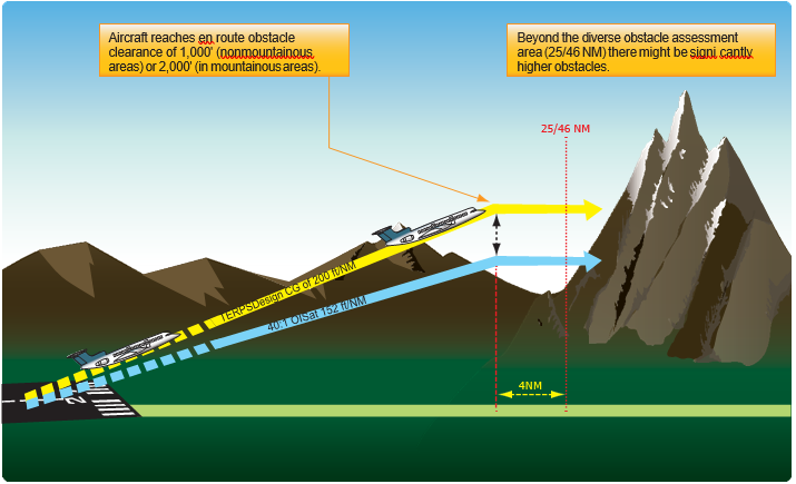
Figure 1-15. Diverse Departure Obstacle Assessment to 25/46 NM.

Figure 1-16. New TERPS departure procedures.
Departure Procedures
Instrument departure procedures are preplanned IFR procedures that provide obstruction clearance from the terminal area to the appropriate en route structure. Primarily, these procedures are designed to provide obstacle protection for departing aircraft. There are two types of Departure Procedures (DPs):
- Obstacle Departure Procedures (ODPs) and
- Standard Instrument Departures (SIDs).
When an instrument approach is initially developed for an airport, the need for an ODP is assessed. If an aircraft may turn in any direction from a runway within the limits of the assessment area and remain clear of obstacles that runway passes what is called a diverse departure assessment, and no ODP is published. A diverse departure assessment ensures that a prescribed, expanding amount of required obstacle clearance (ROC) is achieved during the climb-out until the aircraft can obtain a minimum 1,000 feet ROC in non-mountainous areas or a minimum 2,000 feet ROC in mountainous areas. Unless specified otherwise, required obstacle clearance for all departures, including diverse, is based on the pilot crossing the departure end of the runway (DER) at least 35 feet above the DER elevation, climbing to 400 feet above the DER elevation before making the initial turn, and maintaining a minimum climb gradient of 200 ft/ NM, unless required to level off by a crossing restriction, until the minimum IFR altitude is reached. Following ODP assessment, a SID may still be established for the purposes of ATC flow management, system enhancement, or noise abatement.
Design Criteria
The design of a departure procedure is based on FAA Order 8260.3, United States Standard for Terminal Instrument Procedures (TERPS), which is a living document that is updated frequently. Departure design criterion begins with the assumption of an initial climb of 200 ft/NM after crossing the DER at a height of at least 35 feet. [Figure 1-14] The aircraft climb path assumption provides a minimum of 35 feet of additional obstacle clearance above the required obstacle clearance (ROC), from the DER outward, to absorb variations ranging from the distance of the static source to the landing gear, to differences in establishing the minimum 200 ft/NM climb gradient, etc. The ROC is the planned separation between the obstacle clearance surface (OCS) and the required climb gradient of 200 ft/NM. The ROC value is zero at the DER elevation and increases along the departure route until the ROC value appropriate for en route flight is achieved. The appropriate ROC value for en route operations is typically achieved about 25 NM for 1,000 feet of ROC in non-mountainous areas, and 46 NM for 2,000 feet of ROC in mountainous areas.
If taking off from a runway using a diverse departure (a runway without a published ODP), beyond these distances the pilot is responsible for obstacle clearance if not operating on a published route, and if below the MEA or MOCA of a published route, or below an ATC-assigned altitude. [Figure 1-15]
Recent changes in TERPS criteria make the OCS lower and more restrictive. [Figure 1-16] However, there are many departures today that were evaluated under the old criteria that allowed some obstacle surfaces to be as high as 35 feet at the DER. [Figure 1-14] Since there is no way for the pilot to determine whether the departure was evaluated using the previous or current criteria, and until all departures have been evaluated using the current criteria, pilots need to be very familiar with the departure environment and associated obstacles, especially if crossing the DER at less than 35 feet.
All departure procedures are initially assessed for obstacle clearance based on a 40:1 Obstacle Clearance Surface (OCS). If no obstacles penetrate this 40:1 OCS, the standard 200 ft/NM climb gradient provides a minimum of 48 ft/NM of clearance above objects that do not penetrate the slope. The departure design must also include the acquisition of positive course guidance (PCG), typically within 5 to 10 NM of the DER for straight departures. Even when aircraft performance greatly exceeds the minimum climb gradient, the published departure routing must always be flown.
Airports publish the declared distances in the A/FD section of the CS. These include takeoff runway available (TORA), takeoff distance available (TODA), accelerate-stop distance available (ASDA), and landing distance available (LDA). These distances are calculated by adding to the full length of paved runway any applicable clearway or stop-way and subtracting from that sum the sections of the runway unsuitable for satisfying the required takeoff run, takeoff, accelerate/stop, or landing distance as shown in Figure 1-16.
Optimally, the 40 to 1 slope would work for every departure design; however, due to terrain and manmade obstacles, it is often necessary to use alternative requirements to accomplish a safe, obstacle-free departure design. In such cases, the design of the departure may incorporate a climb gradient greater than 200 ft/NM, an increase in the standard takeoff minimums to allow the aircraft to“see and avoid” the obstacles, a standard climb of 200 ft/NM with a specified reduced takeoff length, or a combination of these options and a specific departure route.
If a departure route is specified, it must be flown in conjunction with the other options.
The obstacle environment may require a climb gradient greater than 200 ft/NM. In these cases, the ROC provided above obstacles is equivalent to 24 percent of the published climb gradient. The required climb gradient, for obstacle purposes on ODPs and SIDs, is obtained by using the formulas:
Standard Formula DoD Option*
CG = O – E CG = (48D + O) – E/D
0.76 D
O = obstacle mean sea level (MSL) elevation E = climb gradient starting MSL elevation
D = distance (NM) from DER to the obstacle
Examples:
2049 – 1221 = 351.44 (48 × 3.1 + 2049) – 1221 = 315.10
0.76 × 3.1 3.1
Round to 352 ft/NM Round to 316 ft/NM
*Military only
These formulas are published in FAA Order 8260.3 for calculating the required climb gradient to clear obstacles.
The following formula is used for calculating SID climb gradients for other than obstacles (i.e., ATC requirements):
CG = A – E /D
A = “climb to” altitude
E = climb gradient starting MSL elevation
D = distance (NM) from the beginning of the climb Example:
3000 – 1221 /5= 355.8 round to 356 ft/NM
Note: The climb gradient must be equal to or greater than the gradient required for obstacles along the route of flight.
The published climb gradient, obstacle or otherwise, is
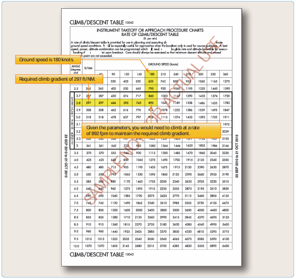
Figure 1-17. Rate of climb table.
treated as a plane which must not be penetrated from above until reaching the stated height or has reached the en route environment (e.g., above the MEA, MOCA). Departure design, including climb gradients, does not take into consideration the performance of the aircraft; it only considers obstacle protection for all aircraft. TERPS criteria assume the aircraft is operating with all available engines and systems fully functioning. Development of contingency procedures, required to cover the case of an engine failure, engine out procedures (EOPs) or other emergency in flight that may occur after liftoff, is the responsibility of the operator. When a climb gradient is required for a specific departure, it is vital that pilots fully understand the performance of their aircraft and determine if it can comply with the required climb. The standard climb of 200 ft/NM is not an issue for most aircraft. When an increased climb gradient is specified due to obstacle issues, it is important to calculate aircraft performance, particularly when flying out of airports at higher altitudes on warm days. To aid in the calculations, the front matter of every TPP booklet contains a rate of climb table that relates specific climb gradients and typical groundspeeds. [Figure 1-17].
Low, Close-In Obstacles
Obstacles that are located within 1 NM of the DER and penetrate the 40:1 OCS are referred to as “low, close-in obstacles”and are also included in the TPP. These obstacles
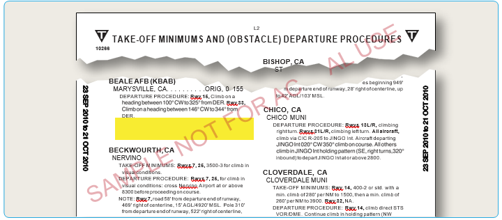
Figure 1-18. Examples of takeoff minimums obstacle clearance.
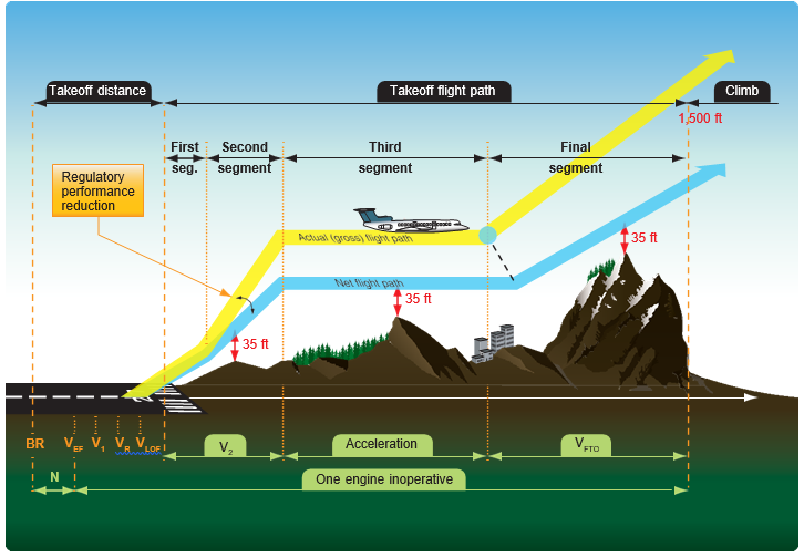
Figure 1-19. Part 25 turbine-powered, transport category airplane OEI actual (gross) takeoff flight path and OEI net takeoff flight path.
are less than 200 feet above the DER elevation, within 1 NM of the runway end, and do not require increased takeoff minimums. The standard ROC to clear these obstacles would require a climb gradient greater than 200 ft/NM for a very short distance, only until the aircraft was 200 feet above the DER. To eliminate publishing an excessive climb gradient, the obstacle above ground level (AGL)/ MSL height and location relative to the DER is noted in the Takeoff Minimums and (Obstacle) Departure Procedures section of a given TPP booklet. The purpose of this note is to identify the obstacle and alert the pilot to the height and location of the obstacle so they can be avoided. This can be accomplished in a variety of ways:
- The pilot may be able to see the obstruction and maneuver around the obstacle(s) if necessary;
- Early liftoff/climb performance may allow the aircraft to cross well above the obstacle(s);
- If the obstacle(s) cannot be visually acquired during departure, preflight planning should take into account what turns or other maneuver(s) may be necessary immediately after takeoff to avoid the obstruction(s).
These obstacles are especially critical to aircraft that do not lift off until close to the DER or which climb at the minimum rate. [Figure 1-18]
One-Engine-Inoperative (OEI) Takeoff Obstacle Clearance Requirements
Large and turbine-powered, multiengine transport category airplanes and commuter category airplanes operated under Part 121 or Part 135 have additional takeoff obstacle clearance requirements beyond the scope of the IFR departure procedure requirements addressed by TERPS.
Part 25 transport category and Part 23 commuter category airplane certification rules define the one-engine• inoperative (OEI) takeoff flight path, which is normally constructed from a series of segments beginning from 35 feet above the runway surface at the end of the OEI takeoff distance and ending at a minimum height of 1,500 feet above the runway elevation. However, the OEI net takeoff flight path assessment may continue above 1,500 feet if necessary to ensure obstacle clearance.
The actual, or gross, OEI flight path represents the vertical OEI climb profile that the aircraft has been demonstrated capable of achieving using takeoff procedures developed for line operations based on the aircraft’s weight, configuration, and environmental conditions at the time of takeoff. The OEI net takeoff flight path represents the actual OEI takeoff flight path that has been degraded by an amount specified by the certification rules to provide a safety margin for expected variations under operational conditions. Subpart I of Part 121 and Part 135 require that the OEI net takeoff flight path be at least 35 feet above obstacles that are located within the prescribed lateral distance either side of the flight path The actual obstacle clearance capability, under optimum conditions after experiencing an engine failure on takeoff, is equal to the difference between gross and net flight path, plus the additional 35 feet. [Figure 1-19]
Advisory Circular (AC) 120-91, Airport Obstacle Analysis, provides guidance and acceptable criteria for use in determining the safe lateral clearance from obstacles, when developing takeoff and initial climb out airport obstacle analyses and engine out obstacle avoidance procedures to comply with the intent of these regulatory requirements. Pilots departing an airport under IFR and operating under Part 121 or 135 are required by 14 CFR 91.175(f )(4) to use an engine-inoperative takeoff obstacle clearance or avoidance procedure that assures compliance with the obstacle clearance requirements (subpart I) of those rules. The assessment of OEI takeoff obstacle clearance is separate and independent of the IFR departure procedure and associated all-engines-operating climb gradient requirements. While the Part 91 operating rules governing large, commuter, and turbine-powered aircraft do not require the use of an OEI takeoff obstacle clearance or avoidance procedure, such use is encouraged for Part 91 operators of these aircraft.
Unlike TERPS, which assesses obstacle clearance beginning at the DER, the OEI net takeoff flight path obstacle assessment begins at the point where the aircraft reaches 35 feet above the runway at the end of the OEI takeoff distance. Therefore, the OEI net takeoff flight path assessment may begin before the DER allowing for the use of a portion of the runway for the OEI climb. The OEI net takeoff flight path obstacle clearance assessment must also account for clearance of the low, close-in obstacles that are noted on the IFR departure procedure, but are not necessarily cleared when complying with the TERPS-based IFR climb gradient. The OEI net takeoff flight path is unique for each aircraft type and is assessed on each takeoff for the required obstacle clearance directly against those obstacles located beneath the OEI flight track and within the prescribed lateral distance from the flight path centerline. TERPS, on the other hand, provides a required climb gradient that represents a surface that the aircraft’s all-engines-operating climb profile must remain above throughout the IFR climb until reaching the en route environment. These two methods of assessing obstacle clearance are necessarily quite different. TERPS is used by the procedure designer
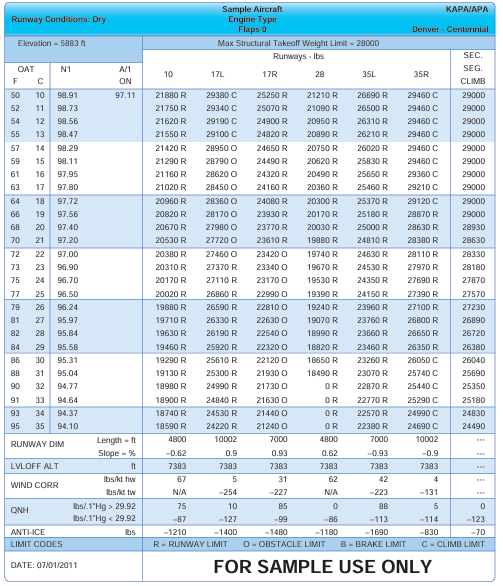
Figure 1-20. Airport/runway analysis example.
to determine a lateral path that is usable by a wide variety of aircraft types, and establishes a clearance plane that aircraft must be able to stay above to fly the procedure. A Part 25 transport category and Part 23 commuter category aircraft’s OEI takeoff flight path is established by or on behalf of the operator for a particular aircraft type and then limit weights are determined that assure clearance of any obstacles under that flight path (or within the prescribed lateral distance from the flight path centerline). It may be necessary for pilots and operators of these categories of aircraft to use the services of an aircraft performance engineer or airport/runway analysis service provider as means of compliance with the requirements of Part 121 subpart I, or Part 135 subpart I concerning OEI net takeoff flight obstacle clearance and takeoff field length requirements. [Figure 1-20] Airport/runway analysis involves the complex, usually computerized, computations of aircraft performance, using extensive airport/obstacle databases and terrain information. This yields maximum allowable takeoff and landing weights for particular aircraft/engine configurations for a specific airport, runway, and range of temperatures. The computations also consider flap settings, various aircraft characteristics, runway conditions, obstacle clearance, and weather conditions. Obstacle data also is available from these service providers for operators who desire to perform their own analysis using the OEI climb performance and flight path data furnished in the Airplane Flight Manual or when using an aircraft electronic performance program supplied by the manufacturer or other service provider. Airport/runway analysis is typically based on the assumption that the pilot will fly a straight-out departure following an engine failure on takeoff. However, when a straight-out departure is not practical or recommended, a special OEI turn procedure can be developed for each applicable runway. This OEI turn procedure may follow the path of a published IFR departure procedure or it may follow an independent path designed to avoid
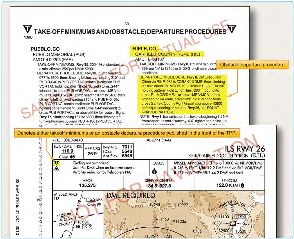
Figure 1-21. Graphic ODP/booklet front matter.
otherwise onerous obstacles and thereby maximize the allowable takeoff weight and payload. Graphic depiction of the OEI procedure is often available to give the pilot a pictorial representation of the special OEI procedure. An engine failure during takeoff is a non-normal condition; therefore, the actions taken by the pilot including the use of an OEI turn procedure takes precedence over noise abatement, air traffic, SIDs, DPs, and other normal operating considerations.
It must be understood that the airport/runway analysis assesses obstacle clearance using the OEI net takeoff flight path data provided in the Airplane Flight Manual and the selected lateral obstacle assessment area. A takeoff weight limit provided on the analysis does not necessarily ensure compliance with the all-engines-operating climb gradient published on an IFR departure procedure even if the track of the OEI special procedure and the IFR departure procedure are identical.
Categories of Departure Procedures
There are two types of DPs: those developed to assist pilots in obstruction avoidance, known as ODPs, printed either textually or graphically, and those developed to communicate ATC clearances, SIDs, always printed graphically.
Obstacle Departure Procedures (ODPs)
The term ODP is used to define procedures that simply provide obstacle clearance. ODPs are only used for obstruction clearance and do not include ATC-related climb requirements. In fact, the primary emphasis of ODP design is to use the least restrictive route of flight to the en route structure or to facilitate a climb to an altitude that allows random (diverse) IFR flight, while attempting to accommodate typical departure routes.
An ODP must be developed when obstructions penetrate the 40:1 departure OCS, as described in FAA Order 8260.3. Only one ODP will be established for a particular runway. This is considered the default IFR departure procedure for a given runway and is intended for pilot awareness and use in the absence of ATC radar vectors or SID assignment. Text is not published to allow an option to use a SID or alternate maneuver assigned by ATC (e.g., “Climb heading 330 to 1200 before turning or use Manchester Departure” or “Turn right, climb direct ABC very high frequency (VHF) omnidirectional range (VOR) or as assigned by ATC.”). ODPs are textual in nature. However, due to the complex nature of some procedures, a visual presentation may be necessary for clarification and understanding. If the ODP is charted graphically, the chart itself includes the word “Obstacle” in parentheses in the title. Additionally, all newly-developed RNAV ODPs are issued in graphical form.
All ODPs are listed in the front of the Aeronautical Information Services approach chart booklets under the heading Takeoff Minimums and Obstacle Departure Procedures. Each procedure is listed in alphabetical order by city and state. The ODP listing in the front of the booklet includes a reference to the graphic chart located in the main body of the booklet if one exists. [Figure 1-21]
ODP Flight Planning Considerations
ODPs are not assigned by ATC unless absolutely necessary to achieve aircraft separation. It is the pilot’s responsibility to determine if there is an ODP published for that airport. If a Part 91 pilot is not given a clearance containing an ODP, SID, or radar vectors and an ODP exists, compliance with such a procedure is the pilot’s choice. A graphic ODP may also be filed in an instrument flight plan by using the computer code included in the procedure title. As a technique, the pilot may enter “will depart (airport) (runway) via textual ODP” in the remarks section of the flight plan. Providing this information to the controller clarifies the intentions of the pilot and helps prevent a potential pilot/controller misunderstanding. If the ODP is not included in the pilot’s clearance, the pilot should inform ATC when an ODP is used for departure from a runway so that ATC can ensure appropriate traffic separation.
During planning, pilots need to determine whether or not the departure airport has an ODP. Remember, an ODP can only be established at an airport that has instrument approach procedures (IAPs). An ODP may drastically affect the initial part of the flight plan. Pilots may have to depart at a higher than normal climb rate, or depart in a direction opposite the intended heading and maintain that for a period of time, any of which would require an alteration in the flight plan and initial headings. Considering the forecast weather, departure runways, and existing ODP, plan the flight route, climb performance, and fuel burn accordingly to compensate for the departure procedure.
Additionally, when close-in obstacles are noted in the Takeoff Minimums and (Obstacle) Departure Procedures section, it may require the pilot to take action to avoid these obstacles. Consideration must be given to decreased climb performance from an inoperative engine or to the amount of runway used for takeoff. Aircraft requiring a short takeoff roll on a long runway may have little concern. On the other hand, airplanes that use most of the available runway for takeoff may not have the standard ROC when climbing at the normal 200 ft/NM.
Another factor to consider is the possibility of an
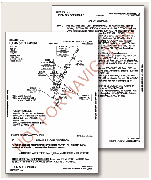
Figure 1-22. SID chart.

Figure 1-23. Transition routes as depicted on SID.
engine failure during takeoff and departure. During the preflight planning, use the aircraft performance charts to determine if the aircraft can still maintain the required climb performance. For high performance aircraft, an engine failure may not impact the ability to maintain the prescribed climb gradients. Aircraft that are performance limited may have diminished capability and may be unable to maintain altitude, let alone complete a climb to altitude. Based on the performance expectations for the aircraft, construct an emergency plan of action that includes emergency checklists and the actions to take to ensure safety in this situation.
Standard Instrument Departures (SIDs)
A SID is an ATC-requested and developed departure route, typically used in busy terminal areas. It is designed at the request of ATC in order to increase capacity of terminal airspace, effectively control the flow of traffic with minimal communication, and reduce environmental impact through noise abatement procedures.
While obstacle protection is always considered in SID routing, the primary goal is to reduce ATC/pilot workload while providing seamless transitions to the en route structure. ATC clearance must be received prior to flying a SID. SIDs also provide additional benefits to both the airspace capacity and the airspace users by reducing radio congestion, allowing more efficient airspace use, and simplifying departure clearances. All of the benefits combine to provide effective, efficient terminal operations, thereby increasing the overall capacity of the NAS.
If you cannot comply with a SID, if you do not possess the charted SID procedure, or if you simply do not wish to use SIDs, include the statement “NO SIDs” in the remarks section of your flight plan. Doing so notifies ATC that they cannot issue you a clearance containing a SID, but instead will clear you via your filed route to the extent possible, or via a Preferential Departure Route (PDR). It should be noted that SID usage not only decreases clearance delivery time, but also greatly simplifies your departure, easing you into the IFR structure at a desirable location and decreases your flight management load. While you are not required to depart using a SID, it may be more difficult to receive an “as filed” clearance when departing busy airports that frequently use SID routing. SIDs are always charted graphically and are located in the TPP after the last approach chart for an airport. The SID may be one or two pages in length, depending on the size of the graphic and the amount of space required for the departure description. Each chart depicts the departure route, navigational fixes, transition routes, and required altitudes. The departure description outlines the particular procedure for each runway. [Figure 1-22]
Transition Routes
Charted transition routes allow pilots to transition from the end of the basic SID to a location in the en route structure. Typically, transition routes fan out in various directions from the end of the basic SID to allow pilots to choose the transition route that takes them in the direction of intended departure. A transition route includes a course, a minimum altitude, and distances between fixes on the route. When filing a SID for a specific transition route, include the transition in the flight plan, using the correct departure and transition code. ATC also assigns transition routes as a means of putting the flight on course to the destination. In any case, the pilot must receive an ATC clearance for the departure and the associated transition, and the clearance from ATC will include both the departure name and transition (e.g., Joe Pool Nine Departure, College Station Transition). [Figure 1-23]
The SID is designed to allow the pilot to provide his or her own navigation with minimal radio communication. This type of procedure usually contains an initial set of departure instructions followed by one or more transition routes. A SID may include an initial segment requiring radar vectors to help the flight join the procedure, but the majority of the navigation remains the pilot’s responsibility. [Figure 1-24]
A radar SID usually requires ATC to provide radar vectors from just after takeoff (ROC is based on a climb to 400 feet above the DER elevation before making the initial turn) until reaching the assigned route or a fix depicted on the SID chart. Radar SIDs do not include departure routes or transition routes because independent pilot navigation is not involved. The procedure sets forth an initial set of departure instructions that typically include an initial heading and altitude. ATC must have radar contact with the aircraft to be able to provide vectors. ATC expects you to immediately comply with radar vectors, and they expect you to notify them if you are unable to fulfill their request. ATC also expects you to make contact immediately if an instruction causes you to compromise safety due to obstructions or traffic.
It is prudent to review radar SID charts prior to use because this type of procedure often includes nonstandard lost communication procedures. If you were to lose radio contact while being vectored by ATC, you would be expected to comply with the lost communication procedure as outlined on the chart, not necessarily those procedures outlined in the AIM. [Figure 1-25]

Figure 1-24. Example of a common SID at Denver, Colorado.
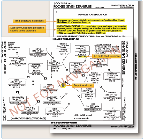
Figure 1-25. Example of a radar SID at Denver, Colorado.
SID Flight Planning Considerations
Take into consideration the departure paths included in the SIDs, and determine if you can use a standardized departure procedure. You have the opportunity to choose the SID that best suits your flight plan. During the flight planning phase, you can investigate each departure, and determine which procedure allows you to depart the airport in the direction of your intended flight. Also consider how a climb gradient to a specific altitude affects the climb time and fuel burn portions of the flight plan. Notes giving procedural requirements are listed on the graphic portion of a departure procedure, and they are mandatory in nature. [Figure 1-26] Mandatory procedural notes may include:
- Aircraft equipment requirements (DME, ADF, etc.)
- ATC equipment in operation (radar)
- Minimum climb requirements
- Restrictions for specific types of aircraft (turbojet only)
- Limited use to certain destinations
Cautionary statements may also be included on the procedure to notify you of specific activity, but these are strictly advisory. [Figure 1-26] If you are unable to comply with a specific requirement, you must not file the procedure as part of your flight plan. If ATC assigns you a SID, you may

Figure 1-26. Departure procedure notes and cautionary statements.
need to quickly recalculate your all-engines-operating performance numbers. If you cannot comply with the climb gradient in the SID, you should not accept a clearance for that SID and furthermore, you must not accept the procedure if ATC assigns it. A clearance for a SID which contains published altitude restrictions may be issued using the phraseology “climb via.” Climb via is an abbreviated clearance that requires compliance with the procedure lateral path, associated speed and altitude restrictions along the cleared route or procedure. Expanded procedures for “Climb via” can be found in the AIM.
ATC can assign SIDs or radar vectors as necessary for traffic management and convenience. To fly a SID, you must receive approval to do so in a clearance. In order to accept a clearance that includes a SID, you must have the charted SID procedure in your possession at the time of departure. It is your responsibility as pilot in command to accept or reject the issuance of a SID by ATC. You must accept or reject the clearance based on:
- The ability to comply with the required performance.
- The ability to navigate to the degree of accuracy required for the procedure.
- Possession of the charted SID procedure.
- Personal understanding of the SID in its entirety.
When you accept a clearance to depart using a SID or radar vectors, ATC is responsible for traffic separation. When departing with a SID, ATC expects you to fly the procedure as charted because the procedure design considers obstacle clearance. It is also expected that you will remain vigilant in scanning for traffic when departing in visual conditions. Furthermore, it is your responsibility to notify ATC if your clearance would endanger your safety or the safety of others. DPs are also categorized by equipment requirements as follows:
- Non-RNAV DP—established for aircraft equipped with conventional avionics using ground-based NAVAIDs.These DPs may also be designed using dead reckoning navigation. Some flight management systems (FMS) are certified to fly a non-RNAV DP if the FMS unit accepts inputs from conventional avionics sources, such as DME, VOR, and localizer (LOC). These inputs include radio tuning and may
- be applied to a navigation solution one at a time or in combination. Some FMS provide for the detection and isolation of faulty navigation information.
- RNAV DP—established for aircraft equipped with RNAV avionics (e.g., GPS, VOR/DME, DME/DME). Automated vertical navigation is not required, and all RNAV procedures not requiring GPS must be annotated with the note: “RADAR REQUIRED.” Prior to using TSO-C129 GPS equipment for RNAV departures, approach receiver autonomous integrity monitoring (RAIM) availability should be checked for that location.
- Radar DP—radar may be used for navigation guidance for SID design. Radar SIDs are established when ATC has a need to vector aircraft on departure to a particular ATS Route, NAVAID, or fix. A fix may be a ground-based NAVAID, a waypoint, or defined by reference to one or more radio NAVAIDs. Not all fixes are waypoints since a fix could be a VOR or VOR/ DME, but all waypoints are fixes. Radar vectors may also be used to join conventional or RNAV navigation SIDs. SIDs requiring radar vectors must be annotated “RADAR REQUIRED.”
Area Navigation (RNAV) Departures
Historically, departure procedures were built around existing ground-based technology and were typically designed to accommodate lower traffic volumes. Often, departure and arrival routes use the same NAVAIDs creating
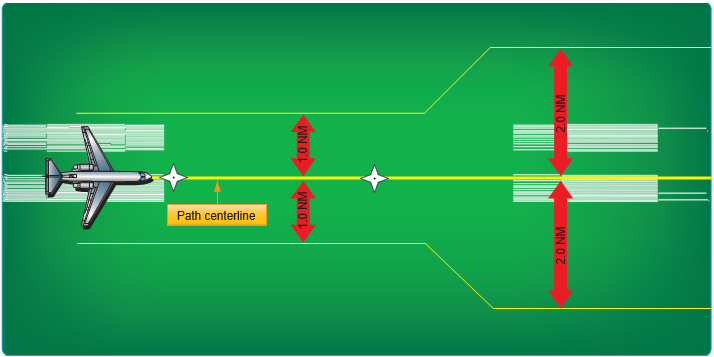
Figure 1-27. RNP departure levels.
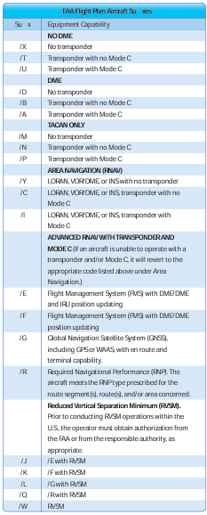
Figure 1-28. Flight plan equipment codes (continued on next page).
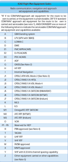
Any alphanumeric characters not indicated above are reserved. E ective September 1, 2005.
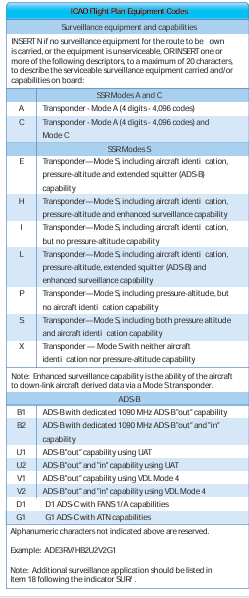
Figure 1-28. Flight plan equipment codes (continued).
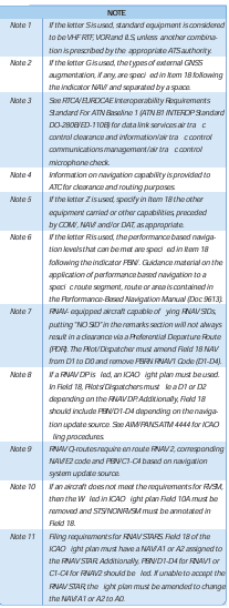
interdependent, capacity diminishing routes. RNAV is a method of navigation that permits aircraft operation on any desired flight path within the coverage of ground- or spaced- based NAVAIDs or within the limits of the capability of self-contained aids or a combination of these. In the future, there will be an increased dependence on the use of RNAV in lieu of routes defined by ground-based NAVAIDs. As a part of the evolving RNAV structure, the FAA has developed departure procedures for pilots flying aircraft equipped with some type of RNAV technology. RNAV allows for the creation of new departure routes that are independent of present fixes and NAVAIDs. RNAV routing is part of the National Airspace Redesign (NAR) and is expected to reduce complexity and increase efficiency of terminal airspace.
When new RNAV departure procedures are designed, they will require minimal vectoring and communications between pilots and ATC. Usually, each departure procedure includes position, time, and altitude, which increase the ability to predict what the pilot will actually do. RNAV departure procedures have the ability to increase the capacity of terminal airspace by increasing on- time departures, airspace utilization, and improved predictability.
All public RNAV SIDs and graphic ODPs are RNAV 1. These procedures generally start with an initial RNAV or heading leg near the departure end runway. In addition, these procedures require system performance currently met by GPS, DME/DME/Inertial Reference Unit (IRU) RNAV systems that satisfy the criteria discussed in AC 90-100, U.S. Terminal and En Route Area Navigation (RNAV) Operations. RNAV departures are identifiable by the inclusion of the term RNAV in the title of the departure. From a required navigation performance (RNP) standpoint, RNAV departure routes are designed with 1 or 2 NM performance standards as listed below. This means you as the pilot and your aircraft equipment must be able to maintain the aircraft within 1 or 2 NM either side of route centerline. [Figure 1-27]
- RNAV 1 procedures require that the aircraft’s total system error remain bounded by ±1 NM for 95 percent of the total flight time.
- RNAV 2 requires a total system error of not more than 2 NM for 95 percent of the total flight time.
RNP is RNAV with on-board monitoring and alerting; RNP is also a statement of navigation performance necessary for operation within defined airspace. RNP 1 (in-lieu-of RNAV 1) is used when a DP that contains a constant radius to a fix (RF) leg or when surveillance (radar) monitoring is not desired for when DME/DME/IRU is used. These procedures are annotated with a standard note: “RNP 1.”
If unable to comply with the requirements of an RNAV or RNP procedure, pilots need to advise ATC as soon as possible. For example, “N1234, failure of GPS system, unable RNAV, request amended clearance.” Pilots are not authorized to fly a published RNAV or RNP procedure unless it is retrievable by the procedure name from the navigation database and conforms to the charted procedure. No other modification of database waypoints or creation of user- defined waypoints on published RNAV or RNP procedures is permitted, except to change altitude and/or airspeed waypoint constraints to comply with an ATC clearance/ instruction, or to insert a waypoint along the published route to assist in complying with an ATC instruction. For example, “Climb via the WILIT departure except cross 30 north of CHUCK at/ or above FL 210.” This is limited only to systems that allow along track waypoint construction.
Pilots of aircraft utilizing DME/DME for primary navigation updating should ensure any required DME stations are in service as determined by NOTAM, ATIS, or ATC advisory. DME/DME navigation system updating may require specific DME facilities to meet performance standards. Based on DME availability evaluations at the time of publication, current DME coverage is not sufficient to support DME/DME RNAV operations everywhere without IRU augmentation or use of GPS. [Figure 1-28] DP chart notes may also include operational information for certain types of equipment, systems, and performance requirements, in addition to the type of RNAV departure procedure.
While operating on RNAV segments, pilots are encouraged to use the flight director in lateral navigation mode. RNAV terminal procedures may be amended by ATC issuing radar vectors and/or clearances direct to a waypoint. Pilots should avoid premature manual deletion of waypoints from their active “legs” page to allow for rejoining procedures. While operating on RNAV segments, pilots operating /R aircraft should adhere to any flight manual limitation or operating procedure required to maintain the RNP value specified for the procedure. In 2008, the FAA implemented the use of en route host automation ICAO flight plan (FP) processing for requesting assignment of RNAV SID, Standard Terminal Arrivals (STARs), or RNAV routes U.S. domestic airspace. This is part of a risk reduction strategy for introduction of the En Route Automation Modernization (ERAM) system in October 2008. ERAM also will use ICAO FP processing and as a result aircrews should be aware that as the FAA updates to ERAM the standard FAA flight plan equipment suffix codes will change to the ICAO flight plan equipment suffix codes. For procedures requiring GPS and/or aircraft approvals requiring GPS, if the navigation system does not automatically alert the flight crew of a loss of GPS, aircraft operators must develop procedures to verify correct GPS
Figure 1-29. Examples of RNAV SID.
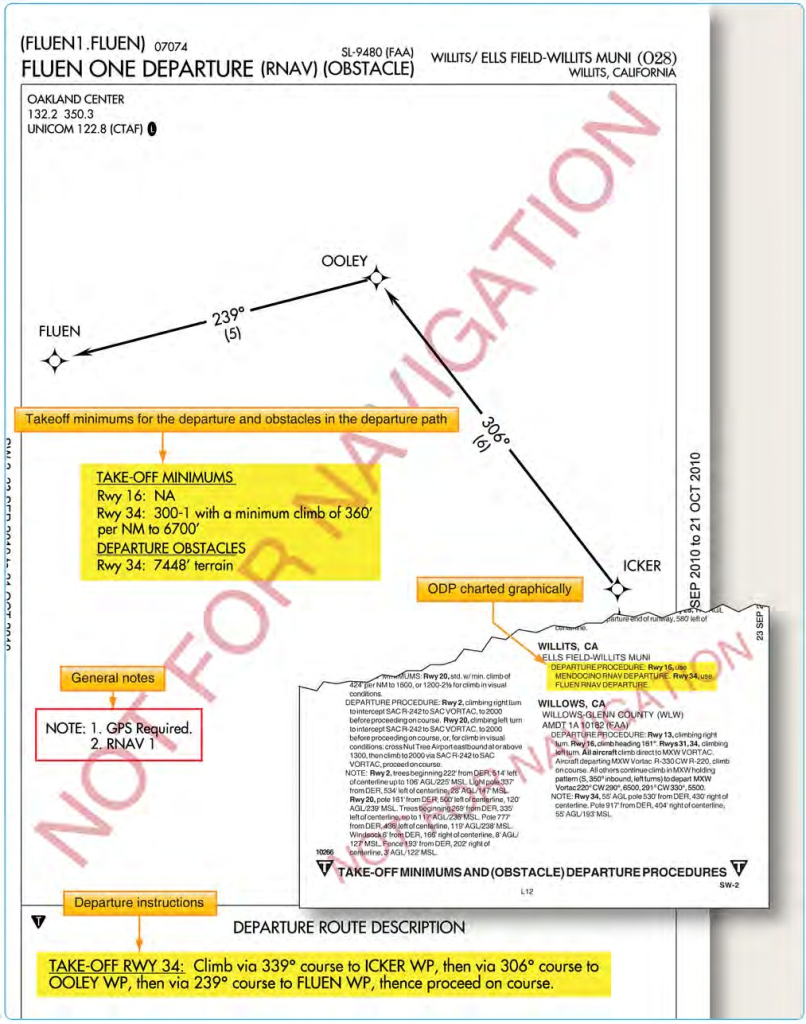
Figure 1-30. Examples of RNAV ODP.
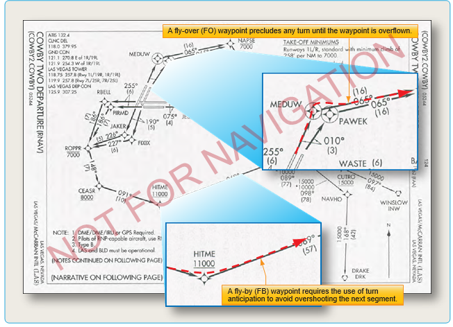
Figure 1-31. Fly-over and fly-by waypoints.
operation. If not equipped with GPS, or for multi-sensor systems with GPS that do not alert upon loss of GPS, aircraft must be capable of navigation system updating using DME/ DME or DME/DME/ IRU for type 1 and 2 procedures. AC 90• 100 may be used as operational guidance for RNAV ODPs. Pilots of FMS-equipped aircraft who are assigned an RNAV DP procedure and subsequently receive a change of runway, transition, or procedure, must verify that the appropriate changes are loaded and available for navigation. [Figures 1-29 and 1-30] Additionally, new waypoint symbols are used in conjunction with RNAV charts. There are two types of waypoints currently in use: fly-by (FB) and fly-over (FO). A FB waypoint typically is used in a position at which a change in the course of procedure occurs. Charts represent them with four- pointed stars. This type of waypoint is designed to allow you to anticipate and begin your turn prior to reaching the waypoint, thus providing smoother transitions. Conversely, RNAV charts show a FO waypoint as a four-pointed star enclosed in a circle. This type of waypoint is used to denote a missed approach point, a missed approach holding point, or other specific points in space that must be flown over. [Figure 1-31] Pilots should not change any database waypoint type from a FB to FO, or vice versa.
There are specific requirements; however, that must be met before using RNAV procedures. Every RNAV departure chart lists general notes and may include specific equipment and performance requirements, as well as the type of RNAV departure procedure in the chart plan view. New aircraft equipment suffix codes are used to denote capabilities for advanced RNAV navigation for flight plan filing purposes. [Figure 1-32]
SID Altitudes
SID altitudes can be charted in four different ways. The first are mandatory altitudes, the second, minimum altitudes, the third, maximum altitudes and the fourth is a combination of minimum and maximum altitudes or also referred to as block altitudes. Below are examples of how each will be shown on a SID chart.
- Mandatory altitudes – 5500
- Minimum altitudes – 2300
- Maximum altitudes – 3300
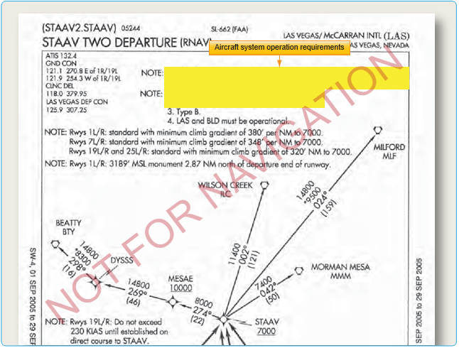
Figure 1-32. Operation requirements for RNAV.
- Combination of minimum and maximum – 7000
4600
Some SIDs may still have “(ATC)” adjacent to a crossing altitude as shown in Figure 1-33 which implies that the crossing altitude is there to support an ATC requirement. A new charting standard has begun a process to remove, over a period of time, the ATC annotation. The Cowboy Four Departure (RNAV) shown in Figure 1-34 depicts the new charting standard without ATC annotations. When necessary, ATC may amend or delete SID crossing altitude restrictions; when doing so, ATC assumes responsibility for obstacle clearance until the aircraft is re-established laterally and vertically on the published SID route.
Pilot Responsibility for Use of RNAV Departures
RNAV usage brings with it multitudes of complications as it is being implemented. It takes time to transition, to disseminate information, and to educate current and potential users. As a current pilot using the NAS, you need to have a clear understanding of the aircraft equipment requirements for operating in a given RNP environment. You must understand the type of navigation system installed in your aircraft, and furthermore, you must know how your system operates to ensure that you can comply with all RNAV requirements. Operational information should be included in your AFM or its supplements. Additional information concerning how to use your equipment to its fullest capacity, including “how to” training, may be gathered from your avionics manufacturer. If you are in doubt about the operation of your avionics system and its ability to comply with RNAV requirements, contact the FAA directly through your local Flight Standards District Office (FSDO). RNAV departure procedures are being developed at a rapid pace to provide RNAV capabilities at all airports. With every chart revision cycle, new RNAV departures are being added for small and large airports. These departures are flown in the same manner as traditional navigation-based departures; pilots are provided headings, altitudes, navigation waypoint, and departure descriptions. RNAV SIDs are found in the TPP with traditional departure procedures.
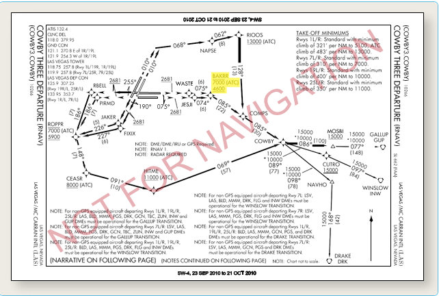
Figure 1-33. Crossing altitude is there to support an ATC requirement.
Radar Departures
A radar departure is another option for departing an airport on an IFR flight. You might receive a radar departure if the airport does not have an established departure procedure, if you are unable to comply with a departure procedure, or if you request“No SIDs” as a part of your flight plan. Expect ATC to issue an initial departure heading if you are being radar vectored after takeoff; however, do not expect to be given a purpose for the specific vector heading. Rest assured that the controller knows your flight route and will vector you into position. By nature of the departure type, once you are issued your clearance, the responsibility for coordination of your flight rests with ATC, including the tower controller and, after handoff, the departure controller who will remain with you until you are released on course and allowed to “resume own navigation.” For all practical purposes, a radar departure is the easiest type of departure to use. It is also a good alternative to a published departure procedure, particularly when none of the available departure procedures are conducive to your flight route. However, it is advisable to always maintain a detailed awareness of your location while you are being radar vectored by ATC. If for some reason radar contact is lost, you will be asked to provide position reports in order for ATC to monitor your flight progress. Also, ATC may release you to“resume own navigation”after vectoring you off course momentarily for a variety of reasons, including weather or traffic.
Upon initial contact, state your aircraft or flight number, the altitude you are climbing through, and the altitude to which you are climbing. The controller will verify that your reported altitude matches that emitted by your transponder. If your altitude does not match, or if you do not have Mode C capabilities, you will be continually required to report your position and altitude for ATC.
The controller is not required to provide terrain and obstacle clearance just because ATC has radar contact with your aircraft. It remains your responsibility until the controller begins to provide navigational guidance in the form of radar vectors. Once radar vectors are given, you are expected to promptly comply with headings and altitudes as assigned. Question any assigned heading if you believe it to be incorrect or if it would cause a violation of a regulation, then advise ATC immediately and obtain a revised clearance.
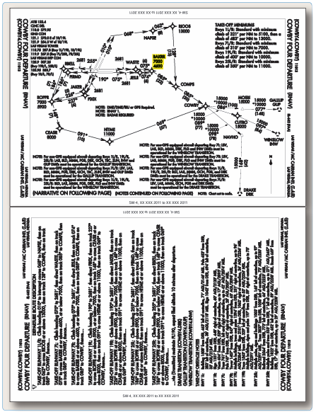
Figure 1-34. New charting standard without ATC annotations.
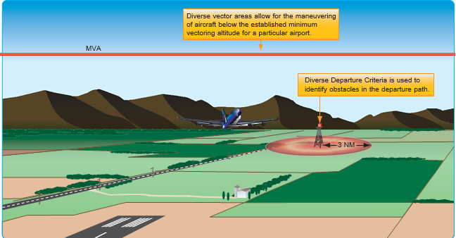
Figure 1-35. Diverse vector area establishment criteria.
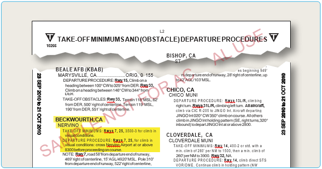
Figure 1-36. Examples of takeoff minimums obstacle clearance.
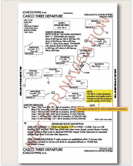
Figure 1-37. Noise abatement SID.
Diverse Vector Area
ATC may establish a minimum vectoring altitude (MVA) around certain airports. This altitude, based on terrain and obstruction clearance, provides controllers with minimum altitudes to vector aircraft in and around a particular location. However, at times, it may be necessary to vector aircraft below this altitude to assist in the efficient flow of departing traffic. For this reason, an airport may have an established Diverse Vector Area (DVA). This DVA may be established below the MVA or Minimum IFR Altitude (MIA) in a radar environment at the request of Air Traffic. This type of DP meets the TERPs criteria for diverse departures, obstacles and terrain avoidance in which random radar vectors below the MVA/MIA may be issued to departing traffic.
The existence of a DVA will be noted in the Takeoff Minimums and Obstacle Departure Procedures section of the U.S. Terminal Procedure Publication (TPP). The Takeoff Departure procedure will be listed first, followed by any applicable DVA. Pilots should be aware that Air Traffic facilities may utilize a climb gradient greater than the standard 200 ft/NM within a DVA. This information will be identified in the DVA text for pilot evaluation against the aircraft’s performance. Pilots should note that the DVA has been assessed for departures which do not follow a specified ground track, but will remain within the specified area. ATC may also vector an aircraft off a previously assigned DP. In all cases, the minimum 200 ft/NM climb gradient is assumed unless a higher is specified on the departure, and obstacle clearance is not provided by ATC until the controller begins to provide navigational guidance (vectors). Lastly, pilots should understand ATC instructions take precedence over an ODP [Figure 1-35].
Visual Climb Over Airport (VCOA)
A visual climb over airport (VCOA) is a departure option for an IFR aircraft, operating in VMC equal to or greater than the specified visibility and ceiling, to visually conduct climbing turns over the airport to the published “climb-to” altitude from which to proceed with the instrument portion of the departure. A VCOA is a departure option developed when obstacles farther than 3 SM from the airport require a CG of more than 200 ft/NM.
These procedures are published in the Take-Off Minimums and (Obstacle) Departure Procedures section of the TPP. [Figure 1-36] Prior to departure, pilots are required to notify ATC when executing the VCOA.
Noise Abatement Procedures
As the aviation industry continues to grow and air traffic increases, so does the population of people and businesses around airports. As a result, noise abatement procedures have become commonplace at most of the nation’s airports. 14 CFR Part 150 specifies the responsibilities of the FAA to investigate the recommendations of the airport operator in a noise compatibility program and approve or disapprove the noise abatement suggestions. This is a crucial step in ensuring that the airport is not unduly inhibited by noise requirements and that air traffic workload and efficiency are not significantly impacted, all while considering the noise problems addressed by the surrounding community.
While most DPs are designed for obstacle clearance and workload reduction, there are some SIDs that are developed solely to comply with noise abatement requirements. Portland International Jetport is an example of an airport where a SID was created strictly for noise abatement purposes as noted in the DP. [Figure 1-36] Typically, noise restrictions are incorporated into the main body of the SID. These types of restrictions require higher departure altitudes, larger climb gradients, reduced airspeeds, and turns to avoid specific areas. Noise restrictions may also be evident during a radar departure. ATC may require you to turn away from your intended course or vector you around a particular area. While these restrictions may seem burdensome, it is important to remember that it is your duty to comply with written and spoken requests from ATC.
Additionally, when required, departure instructions specify the actual heading to be flown after takeoff, as is the case in Figure 1-37 under the departure route description, “Climb via heading 112 degrees…”Some existing procedures specify, “Climb runway heading.”Over time, both of these departure instructions will be updated to read, “Climb heading 112 degrees ” Runway heading is the magnetic direction that
corresponds with the runway centerline extended (charted on the airport diagram), not the numbers painted on the runway. Pilots cleared to “fly or maintain runway heading” are expected to fly or maintain the published heading that corresponds with the extended centerline of the departure runway (until otherwise instructed by ATC), and are not to apply drift correction (e.g., RWY 11, actual magnetic heading of the runway centerline 112.2 degrees, “fly heading 112 degrees”). In the event of parallel departures, this prevents a loss of separation caused by only one aircraft applying a wind drift.
Procedural Notes
An important consideration to make during your flight planning is whether or not you are able to fly your chosen departure procedure as charted.
DP Responsibilities
Responsibility for the safe execution of DPs rests on the shoulders of both ATC and the pilot. Without the interest and attention of both parties, the IFR system cannot work in harmony, and achievement of safety is impossible.
ATC, in all forms, is responsible for issuing clearances appropriate to the operations being conducted, assigning altitudes for IFR flight above the minimum IFR altitudes for a specific area of controlled airspace, ensuring the pilot has acknowledged the clearance or instructions, and ensuring the correct read back of instructions. Specifically related to departures, ATC is responsible for specifying the direction of takeoff or initial heading when necessary, obtaining pilot concurrence that the procedure complies with local traffic patterns, terrain, and obstruction clearance, and including DP as part of the ATC clearance when pilot compliance for separation is necessary.
The pilot has a number of responsibilities when simply operating in conjunction with ATC or when using DPs under an IFR clearance:
- Acknowledge receipt and understanding of an ATC clearance.
- Read back any part of a clearance that contains“hold short” instructions.
- Request clarification of clearances.
- Request an amendment to a clearance if it is c unacceptable from a safety perspective
- Promptly comply with ATC requests. Advise ATC immediately if unable
to comply with a clearance. - You are required to contact ATC if you are unable to comply with all-engines-operating climb gradients and climb rates. It is also expected that you are capable of maintaining the climb gradient outlined in either a standard or non-standard DP. If you cannot maintain a standard climb gradient or the climb gradient specified in an ODP, you must wait until you can depart under VMC.
When planning for a departure, pilots should:
- Consider the type of terrain and other obstructions in the vicinity of the airport.
- Determine if obstacle clearance can be maintained visually, or if they need to make use of a DP.
- Determine if an ODP or SID is available for the departure airport.
- Determine what actions allow for a safe departure out of an airport that does not have any type of affiliated DPs.
By simply complying with DPs in their entirety as published, obstacle clearance is guaranteed. Depending on the type of departure used, responsibility for terrain clearance and traffic separation may be shared between pilots and controllers.
Departures From Tower-Controlled Airports
Departing from a tower-controlled airport is relatively simple in comparison to departing from non-towered airport. Normally you request your IFR clearance through ground control or clearance delivery. Communication frequencies for the various controllers are listed on departure, approach, and airport charts, as well as the Chart Supplement (CS). At some airports, you may have the option of receiving a pre-taxi clearance. This program allows you to call ground control or clearance delivery no more than 10 minutes prior to beginning taxi operations and receive your IFR clearance. A pre-departure clearance (PDC) program that allows pilots to receive a clearance via data link from a dispatcher or a data link communications service provider, e.g. ARINC, is available for Part 121 and 135 operators. A clearance is given to the dispatcher, who in turn, relays it to the crew, enabling the crew to bypass communication with clearance delivery, thus reducing frequency congestion. Once you have received your clearance, it is your responsibility to comply with the instructions as given, and notify ATC if you are unable to comply with the clearance. If you do not understand the clearance, or if you think that you have missed a portion of the clearance, contact ATC immediately for clarification.
Departures From Airports Without an Operating Control Tower
There are hundreds of airports across the United States that operate successfully every day without the benefit of a control tower. While a tower is certainly beneficial when departing IFR, most other departures can be made with few challenges. As usual, you must file your flight plan at least 30 minutes in advance. During your planning phase, investigate the departure airport’s method for receiving an instrument clearance. You can contact the Flight Service Station (FSS) on the ground by telephone, and they will request your clearance from ATC. Typically, when a clearance is given in this manner, the clearance includes a void time. You must depart the airport before the clearance void time; if you fail to depart, you must contact ATC by a specified notification time, which is within 30 minutes of the original void time. After the clearance void time, your reserved space within the IFR system is released for other traffic.
There are several other ways to receive a clearance at a non- towered airport. If you can contact the FSS or ATC on the radio, you can request your departure clearance. However, these frequencies are typically congested, and they may not be able to provide you with a clearance via the radio. You also can use a Remote Communications Outlet (RCO) to contact a FSS if one is located nearby. Some airports have licensed UNICOM operators that can also contact ATC on your behalf and, in turn, relay your clearance from ATC. You are also allowed to depart the airport VFR, if conditions permit, and contact the controlling authority to request your clearance in the air. If there is a direct line to the controlling ATC Facility, the phone number is published in the Chart Supplement U.S. (formerly Airport/Facility Directory (A/FD). As technology improves, new methods for delivery of clearances at non-towered airports are being created.
Ground Communication Outlet
Ground Communication Outlets (GCO), have been developed in conjunction with the FAA to provide pilots flying in and out of non-towered airports with the capability to contact ATC and AFSS via very high frequency (VHF) radio to a telephone connection. This lets pilots obtain an instrument clearance or close a VFR/IFR flight plan. You can use four key clicks on your VHF radio to contact the nearest ATC facility and six key clicks to contact the local AFSS, but it is intended to be used only as a ground operational tool. A GCO is an unstaffed, remote controlled ground-to-ground communication facility that is relatively inexpensive to install and operate. Installations of these types of outlets are scheduled at instrument airports around the country. GCOs are manufactured by different companies including ARINC and AVTECH, each with different operating characteristics but with the ability to accomplish the same goal. This latest technology has proven to be an incredibly useful tool for communicating with the appropriate authorities when departing IFR from a non-towered airport. The GCO should help relieve the need to use the telephone to call ATC and the need to depart into marginal conditions just to achieve radio contact. GCO information is listed on airport charts and instrument approach charts with other communications frequencies. Signs may also be located on an airport to notify you of the frequency and proper usage.
See and Avoid Techniques
Meteorological conditions permitting, you are required to use “see and avoid” techniques to avoid traffic, terrain, and other obstacles. To avoid obstacles during a departure, the takeoff minimums may include a non-standard ceiling and visibility minimum. These are given to pilots so they can depart an airport without being able to meet the established climb gradient. Instead, they must see and avoid obstacles in the departure path. In these situations, ATC provides radar traffic information for radar-identified aircraft outside controlled airspace, workload permitting, and safety alerts to pilots believed to be within an unsafe proximity to obstacles or aircraft.
VFR Departures
There may be times when you need to fly an IFR flight plan due to the weather you will encounter at a later time (or if you simply wish to fly IFR to remain proficient), but the weather outside is clearly VFR. It may be that you can depart VFR, but you need to get an IFR clearance shortly after departing the airport. A VFR departure can be used as a tool that allows you to get off the ground without having to wait for a time slot in the IFR system, however, departing VFR with the intent of receiving an IFR clearance in the air can also present serious hazards worth considering.
A VFR departure dramatically changes the takeoff responsibilities for you and for ATC. Upon receiving clearance for a VFR departure, you are cleared to depart; however, you must maintain separation between yourself and other traffic. You are also responsible for maintaining terrain and obstruction clearance, as well as remaining in VFR weather conditions. You cannot fly in IMC without first receiving your IFR clearance. Likewise, a VFR departure relieves ATC of these duties and basically requires them only to provide you with safety alerts as workload permits.
Maintain VFR until you have obtained your IFR clearance and have ATC approval to proceed on course in accordance with your clearance. If you accept this clearance and are below the minimum IFR altitude for operations in the area, you accept responsibility for terrain/obstruction clearance until you reach that altitude.


