Gyroplanes are available in a wide variety of designs that range from amateur built to FAA-certificated air- craft. Similarly, the complexity of the systems integrated in gyroplane design cover a broad range. To ensure the airworthiness of your aircraft, it is important that you thoroughly understand the design and operation of each system employed by your machine.
Propulsion systems
Most of the gyroplanes flying today use a reciprocating engine mounted in a pusher configuration that drives either a fixed or constant speed propeller. The engines used in amateur-built gyroplanes are normally proven powerplants adapted from automotive or other uses. Some amateur-built gyroplanes use FAA-certificated air- craft engines and propellers. Auto engines, along with some of the other powerplants adapted to gyroplanes, operate at a high r.p.m., which requires the use of a reduc- tion unit to lower the output to efficient propeller speeds.
Early auto gyros used existing aircraft engines, which drove a propeller in the tractor configuration. Several amateur-built gyroplanes still use this propulsion con- figuration, and may utilize a certificated or an uncertificated engine. Although not in use today, turboprop and pure jet engines could also be used for the propulsion of a gyroplane.
Rotor systems
SEMIRIGID ROTOR SYSTEM
Any rotor system capable of autorotation may be utilized in a gyroplane. Because of its simplicity, the most widely used system is the semirigid, teeter-head system. This system is found in most amateur-built gyroplanes. [Figure 18-1] In this system, the rotor head is mounted on a spindle, which may be tilted for control. The rotor blades are attached to a hub bar that may or may not have adjustments for varying the blade pitch. A coning angle, determined by projections of blade weight, rotor speed, and load to be carried, is built into the hub bar. This minimizes hub bar bending moments and eliminates the need for a coning hinge, which is used in more complex rotor systems. A tower block pro- vides the undersling and attachment to the rotor head by the teeter bolt. The rotor head is comprised of a bearing block in which the bearing is mounted and onto which the tower plates are attached. The spindle (commonly, a vertically oriented bolt) attaches the rotating portion of the head to the non-rotating torque tube. The torque tube is mounted to the airframe through attachments allowing both lateral and longitudinal movement. This allows the movement through which control is achieved.
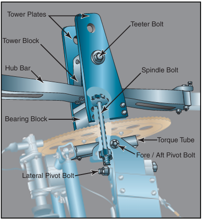
Figure 18-1. The semirigid, teeter-head system is found on most amateur-built gyroplanes. The rotor hub bar and blades are permitted to tilt by the teeter bolt.
FULLY ARTICULATED ROTOR SYSTEM
The fully articulated rotor system is found on some gyroplanes. As with helicopter-type rotor systems, the articulated rotor system allows the manipulation of
Coning Angle—An angular deflection of the rotor blades upward from the rotor hub.
Undersling—A design character- istic that prevents the distance between the rotor mast axis and the center of mass of each rotor blade from changing as the blades teeter. This precludes Coriolis Effect from acting on the speed of the rotor system.
Undersling is further explained in Chapter 3—Aerodynamics of Flight, Coriolis Effect (Law of Conservation of Angular Momentum).
rotor blade pitch while in flight. This system is significantly more complicated than the teeter-head, as it requires hinges that allow each rotor blade to flap, feather, and lead or lag independently. [Figure 18-2] When used, the fully articulated rotor system of a gyro- plane is very similar to those used on helicopters, which is explained in depth in Chapter 5—Helicopter Systems, Main Rotor Systems. One major advantage of using a fully articulated rotor in gyroplane design is that it usually allows jump takeoff capability. Rotor characteristics required for a successful jump takeoff must include a method of collective pitch change, a blade with sufficient inertia, and a prerotation mechanism capable of approximately 150 percent of rotor flight r.p.m.
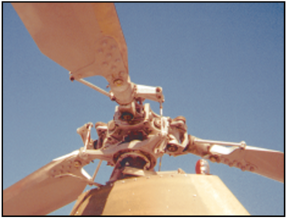
Figure 18-2. The fully articulated rotor system enables the pilot to effect changes in pitch to the rotor blades, which is necessary for jump takeoff capability.
Incorporating rotor blades with high inertia potential is desirable in helicopter design and is essential for jump takeoff gyroplanes. A rotor hub design allowing the rotor speed to exceed normal flight r.p.m. by over 50 percent is not found in helicopters, and predicates a rotor head design particular to the jump takeoff gyroplane, yet very similar to that of the helicopter.
Prerotator
Prior to takeoff, the gyroplane rotor must first achieve a rotor speed sufficient to create the necessary lift. This is accomplished on very basic gyroplanes by initially spinning the blades by hand. The aircraft is then taxied with the rotor disc tilted aft, allowing airflow through the system to accelerate it to flight r.p.m. More advanced gyroplanes use a prerotator, which provides a mechanical means to spin the rotor. Many prerotators are capable of only achieving a portion of the speed necessary for flight; the remainder is gained by taxiing or during the takeoff roll. Because of the wide variety of prerotation systems available, you need to become thoroughly familiar with the characteristics and techniques associated with your particular system.
MECHANICAL PREROTATOR
Mechanical prerotators typically have clutches or belts for engagement, a drive train, and may use a transmission to transfer engine power to the rotor. Friction drives and flex cables are used in conjunction with an automotive type bendix and ring gear on many gyro- planes. [Figure 18-3]
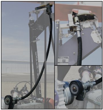
Figure 18-3. The mechanical prerotator used by many gyro- planes uses a friction drive at the propeller hub, and a flexi- ble cable that runs from the propeller hub to the rotor mast. When engaged, the bendix spins the ring gear located on the rotor hub.
The mechanical prerotator used on jump takeoff gyro- planes may be regarded as being similar to the helicopter main rotor drive train, but only operates while the air- craft is firmly on the ground. Gyroplanes do not have an antitorque device like a helicopter, and ground contact is necessary to counteract the torque forces generated by the prerotation system. If jump takeoff capability is designed into a gyroplane, rotor r.p.m. prior to liftoff must be such that rotor energy will support the air- craft through the acceleration phase of takeoff. This combination of rotor system and prerotator utilizes the transmission only while the aircraft is on the ground, allowing the transmission to be disconnected from both the rotor and the engine while in normal flight.
HYDRAULIC PREROTATOR
The hydraulic prerotator found on gyroplanes uses engine power to drive a hydraulic pump, which in turn drives a hydraulic motor attached to an automotive type bendix and ring gear. [Figure 18-4] This system also requires that some type of clutch and pressure regulation be incorporated into the design.
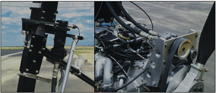
Figure 18-4. This prerotator uses belts at the propeller hub to drive a hydraulic pump, which drives a hydraulic motor on the rotor mast.
ELECTRIC PREROTATOR
The electric prerotator found on gyroplanes uses an automotive type starter with a bendix and ring gear mounted at the rotor head to impart torque to the rotor system. [Figure 18-5] This system has the advantage of simplicity and ease of operation, but is dependent on having electrical power available. Using a “soft start” device can alleviate the problems associated with the high starting torque initially required to get the rotor system turning. This device delivers electrical pulses to the starter for approximately 10 seconds before connecting uninterrupted voltage.
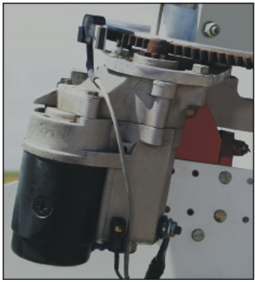
Figure 18-5. The electric prerotator is simple and easy to use, but requires the availability of electrical power.
TIP JETS
Jets located at the rotor blade tips have been used in sev- eral applications for prerotation, as well as for hover flight. This system has no requirement for a transmission or clutches. It also has the advantage of not imparting torque to the airframe, allowing the rotor to be powered in flight to give increased climb rates and even the ability to hover. The major disadvantage is the noise generated by the jets. Fortunately, tip jets may be shut down while operating in the autorotative gyroplane mode.
Instrumentation
The instrumentation required for flight is generally related to the complexity of the gyroplane. Some gyro- planes using air-cooled and fuel/oil-lubricated engines may have limited instrumentation.
ENGINE INSTRUMENTS
All but the most basic engines require monitoring instrumentation for safe operation. Coolant tempera- ture, cylinder head temperatures, oil temperature, oil pressure, carburetor air temperature, and exhaust gas temperature are all direct indications of engine opera- tion and may be displayed. Engine power is normally indicated by engine r.p.m., or by manifold pressure on gyroplanes with a constant speed propeller.
ROTOR TACHOMETER
Most gyroplanes are equipped with a rotor r.p.m. indica- tor. Because the pilot does not normally have direct control of rotor r.p.m. in flight, this instrument is most useful on the takeoff roll to determine when there is sufficient rotor speed for liftoff. On gyroplanes not equipped with a rotor tachometer, additional piloting skills are required to sense rotor r.p.m. prior to takeoff.
Certain gyroplane maneuvers require you to know pre- cisely the speed of the rotor system. Performing a jump takeoff in a gyroplane with collective control is one example, as sufficient rotor energy must be available for the successful outcome of the maneuver. When variable collective and a rotor tachometer are used, more efficient rotor operation may be accomplished by using the lowest practical rotor r.p.m. [Figure 18-6]
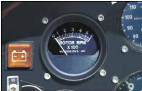
Figure 18-6. A rotor tachometer can be very useful to deter- mine when rotor r.p.m. is sufficient for takeoff.
SLIP/SKID INDICATOR
A yaw string attached to the nose of the aircraft and a conventional inclinometer are often used in gyroplanes to assist in maintaining coordinated flight. [Figure 18-7]
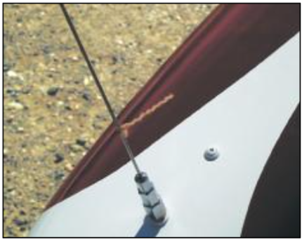
Figure 18-7. A string simply tied near the nose of the gyro- plane that can be viewed from the cockpit is often used to indicate rotation about the yaw axis. An inclinometer may also be used.
AIRSPEED INDICATOR
Airspeed knowledge is essential and is most easily obtained by an airspeed indicator that is designed for speed indicator is used, as in some very basic amateur-built machines, you must have a very acute sense of “q” (impact air pressure against your body).
ALTIMETER
For the average pilot, it becomes increasingly difficult to judge altitude accurately when more than several hundred feet above the ground. A conventional altime- ter may be used to provide an altitude reference when flying at higher altitudes where human perception degrades.
IFR FLIGHT INSTRUMENTATION
Gyroplane flight into instrument meteorological condi- tions requires adequate flight instrumentation and navi- gational systems, just as in any aircraft. Very few gyroplanes have been equipped for this type of operation. The majority of gyroplanes do not meet the stability requirements for single-pilot IFR flight. As larger and more advanced gyroplanes are developed, issues of IFR flight in these aircraft will have to be addressed.
Ground handling
The gyroplane is capable of ground taxiing in a manner similar to that of an airplane. A steerable nose wheel, which may be combined with independent main wheel brakes, provides the most common method of control. [Figure 18-8] The use of independent main wheel brakes allows differential braking, or applying more braking to one wheel than the other to achieve tight radius turns. On some gyroplanes, the steerable nose wheel is equipped with a foot-operated brake rather than using main wheel brakes. One limitation of this system is that the nose wheel normally supports only a fraction of the weight of the gyroplane, which greatly reduces braking effectiveness. Another drawback is the
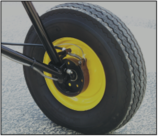
Figure 18-8. Depending on design, main wheel brakes can be operated either independently or collectively. They are considerably more effective than nose wheel brakes.
inability to use differential braking, which increases the radius of turns.
The rotor blades demand special consideration during ground handling, as turning rotor blades can be a hazard to those nearby. Many gyroplanes have a rotor brake that may be used to slow the rotor after landing, or to secure the blades while parked. A parked gyro- plane should never be left with unsecured blades, because even a slight change in wind could cause the blades to turn or flap.


