It is vital to comply with weight and balance limits established for helicopters. Operating above the maxi- mum weight limitation compromises the structural integrity of the helicopter and adversely affects per- formance. Balance is also critical because on some fully loaded helicopters, center of gravity deviations as small as three inches can dramatically change a heli- copter’s handling characteristics. Taking off in a helicopter that is not within the weight and balance limitations is unsafe.
Weight
When determining if your helicopter is within the weight limits, you must consider the weight of the basic helicopter, crew, passengers, cargo, and fuel. Although the effective weight (load factor) varies during maneu- vering flight, this chapter primarily considers the weight of the loaded helicopter while at rest.
The following terms are used when computing a heli- copter’s weight.
BASIC EMPTY WEIGHT—The starting point for weight computations is the basic empty weight, which is the weight of the standard helicopter, optional equipment, unusable fuel, and full operating fluids including full engine oil. Some helicopters might use the term “licensed empty weight,” which is nearly the same as basic empty weight, except that it does not include full engine oil, just undrainable oil. If you fly a helicopter that lists a licensed empty weight, be sure to add the weight of the oil to your computations.
USEFUL LOAD—The difference between the gross weight and the basic empty weight is referred to as useful load. It includes the flight crew, usable fuel, drainable oil, if applicable, and payload.
PAYLOAD—The weight of the passengers, cargo, and baggage.
GROSS WEIGHT—The sum of the basic empty weight and useful load.
MAXIMUM GROSS WEIGHT— The maximum weight of the helicopter. Most helicopters have an inter- nal maximum gross weight, which refers to the weight within the helicopter structure and an external maximum gross weight, which refers to the weight of the helicopter with an external load.
WEIGHT LIMITATIONS
Weight limitations are necessary to guarantee the struc- tural integrity of the helicopter, as well as enabling you to predict helicopter performance accurately. Although aircraft manufacturers build in safety factors, you should never intentionally exceed the load limits for which a helicopter is certificated. Operating above a maximum weight could result in structural deformation or failure during flight if you encounter excessive load factors, strong wind gusts, or turbulence. Operating below a minimum weight could adversely affect the handling characteristics of the helicopter. During sin- gle-pilot operations in some helicopters, you may have to use a large amount of forward cyclic in order to maintain a hover. By adding ballast to the helicopter, the cyclic will be closer to the center, which gives you a greater range of control motion in every direction. Additional weight also improves autorotational charac- teristics since the autorotational descent can be estab- lished sooner. In addition, operating below minimum weight could prevent you from achieving the desirable rotor r.p.m. during autorotations.
Although a helicopter is certificated for a specified maximum gross weight, it is not safe to take off with this load under all conditions. Anything that adversely affects takeoff, climb, hovering, and landing perform- ance may require off-loading of fuel, passengers, or baggage to some weight less than the published maxi- mum. Factors which can affect performance include high altitude, high temperature, and high humidity con- ditions, which result in a high density altitude.
DETERMINING EMPTY WEIGHT
A helicopter’s weight and balance records contain essential data, including a complete list of all installed optional equipment. Use these records to determine the weight and balance condition of the empty helicopter.
When a helicopter is delivered from the factory, the basic empty weight, empty weight center of gravity (CG), and useful load are recorded on a weight and balance data sheet included in the FAA-Approved Rotocraft Flight Manual. The basic empty weight can vary even in the same model of helicopter because of differences in installed equipment. If the owner or operator of a helicopter has equipment removed, replaced, or additional equipment installed, these changes must be reflected in the weight and balance records. In addition, major repairs or alterations must be recorded by a certified mechanic. When the revised weight and moment are recorded on a new form, the old record is marked with the word “superseded” and dated with the effective date of the new record. This makes it easy to determine which weight and balance form is the latest version. You must use the latest weight and balance data for computing all loading problems.
Balance
Helicopter performance is not only affected by gross weight, but also by the position of that weight. It is essential to load the aircraft within the allowable center- of-gravity range specified in the rotorcraft flight manual’s weight and balance limitations.
CENTER OF GRAVITY (CG)
The center of gravity is defined as the theoretical point where all of the aircraft’s weight is considered to be concentrated. If a helicopter was suspended by a cable attached to the center-of-gravity point, it would balance like a teeter-totter. For helicopters with a single main rotor, the CG is usually close to the main rotor mast.
Improper balance of a helicopter’s load can result in serious control problems. The allowable range in which the CG may fall is called the “CG range.” The exact CG location and range are specified in the rotorcraft flight manual for each helicopter. In addition to making a helicopter difficult to control, an out-of-balance load- ing condition also decreases maneuverability since cyclic control is less effective in the direction opposite to the CG location.
Ideally, you should try to perfectly balance a helicopter so that the fuselage remains horizontal in hovering flight, with no cyclic pitch control needed except for wind correction. Since the fuselage acts as a pendulum suspended from the rotor, changing the center of gravity changes the angle at which the aircraft hangs from the rotor. When the center of gravity is directly under the rotor mast, the helicopter hangs horizontal; if the CG is too far forward of the mast, the helicopter hangs with its nose tilted down; if the CG is too far aft of the mast, the nose tilts up. [Figure 7-1]
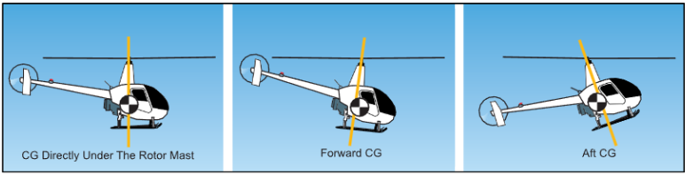
Figure 7-1. The location of the center of gravity strongly influences how the helicopter handles.
sive forward displacement of cyclic control to main- tain a hover in a no-wind condition. If there is a wind, you need even greater forward cyclic.
If flight is continued in this condition, you may find it impossible to fly in the upper allowable airspeed range due to inadequate forward cyclic authority to maintain a nose-low attitude. In addition, with an extreme aft CG, gusty or rough air could accelerate the helicopter to a speed faster than that produced with full forward cyclic control. In this case, dissymmetry of lift and blade flap- ping could cause the rotor disc to tilt aft. With full for- ward cyclic control already applied, you might not be able to lower the rotor disc, resulting in possible loss of control, or the rotor blades striking the tailboom.
LATERAL BALANCE
For most helicopters, it is usually not necessary to determine the lateral CG for normal flight instruction and passenger flights. This is because helicopter cab- ins are relatively narrow and most optional equipment is located near the center line. However, some helicopter manuals specify the seat from which you must conduct solo flight. In addition, if there is an unusual situation, such as a heavy pilot and a full load of fuel on one side of the helicopter, which could affect the lateral CG, its position should be checked against the CG envelope. If carrying external loads in a position that requires large lateral cyclic control displacement to maintain level flight, fore and aft cyclic effectiveness could be dramatically limited.
Weight and balance calculations
When determining whether your helicopter is properly loaded, you must answer two questions:
- Is the gross weight less than or equal to the max- imum allowable gross weight?
- Is the center of gravity within the allowable CG range, and will it stay within the allowable range as fuel is burned off?
To answer the first question, just add the weight of the items comprising the useful load (pilot, passengers, fuel, oil, if applicable, cargo, and baggage) to the basic empty weight of the helicopter. Check that the total weight does not exceed the maximum allowable gross weight.
To answer the second question, you need to use CG or moment information from loading charts, tables, or graphs in the rotorcraft flight manual. Then using one of the methods described below, calculate the loaded moment and/or loaded CG and verify that it falls within the allow- able CG range shown in the rotorcraft flight manual.
It is important to note that any weight and balance computation is only as accurate as the information provided. Therefore, you should ask passengers what they weigh and add a few pounds to cover the additional weight of clothing, especially during the winter months. The bag- gage weight should be determined by the use of a scale, if practical. If a scale is not available, be conservative and overestimate the weight. Figure 7-2 indicates the standard weights for specific operating fluids.
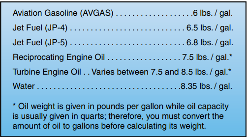
Figure 7-2. When making weight and balance computations, always use actual weights if they are available, especially if the helicopter is loaded near the weight and balance limits.
The following terms are used when computing a heli- copter’s balance.
REFERENCE DATUM—Balance is determined by the location of the CG, which is usually described as a given number of inches from the reference datum. The horizontal reference datum is an imaginary vertical plane or point, arbitrarily fixed somewhere along the longitudinal axis of the helicopter, from which all horizontal distances are measured for weight and balance purposes. There is no fixed rule for its location. It may be located at the rotor mast, the nose of the helicopter, or even at a point in space ahead of the helicopter. [Figure 7-3]
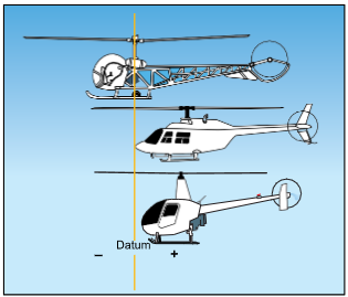
Figure 7-3. While the horizontal reference datum can be any- where the manufacturer chooses, most small training heli- copters have the horizontal reference datum 100 inches forward of the main rotor shaft centerline. This is to keep all the computed values positive.
The lateral reference datum, is usually located at the center of the helicopter. The location of the reference datums is established by the manufacturer and is defined in the rotorcraft flight manual. [Figure 7-4]
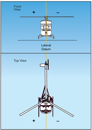
Figure 7-4. The lateral reference datum is located longitudinally through the center of the helicopter; therefore, there are positive and negative values.
ARM—The horizontal distance from the datum to any component of the helicopter or to any object located within the helicopter is called the arm. Another term that can be used interchangeably with arm is station. If the component or object is located to the rear of the datum, it is measured as a positive number and usu- ally is referred to as inches aft of the datum. Conversely, if the component or object is located for- ward of the datum, it is indicated as a negative num- ber and is usually referred to as inches forward of the datum.
MOMENT—If the weight of an object is multiplied by its arm, the result is known as its moment. You may think of moment as a force that results from an object’s weight acting at a distance. Moment is also referred to as the tendency of an object to rotate or pivot about a point. The farther an object is from a pivotal point, the greater its force.
CENTER OF GRAVITY COMPUTATION—By totaling the weights and moments of all components and objects carried, you can determine the point where a loaded helicopter would balance. This point is known as the center of gravity.
Weight and balance methods
Since weight and balance is so critical to the safe oper- ation of a helicopter, it is important to know how to check this condition for each loading arrangement. Most helicopter manufacturers use one of two meth- ods, or a combination of the methods, to check weight and balance conditions.
COMPUTATIONAL METHOD
With the computational method, you use simple mathematics to solve weight and balance problems. The first step is to look up the basic empty weight and total moment for the particular helicopter you fly. If the center of gravity is given, it should also be noted. The empty weight CG can be considered the arm of the empty helicopter. This should be the first item recorded on the weight and balance form. [Figure 7-5]
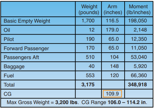
Figure 7-5. In this example, the helicopter’s weight of 1,700 pounds is recorded in the first column, its CG or arm of 116.5 inches in the second, and its moment of 198,050 pound- inches in the last. Notice that the weight of the helicopter, multiplied by its CG, equals its moment.
Next, the weights of the oil, if required, pilot, passengers, baggage, and fuel are recorded. Use care in recording the weight of each passenger and baggage. Recording each weight in its proper location is extremely important to the accurate calculation of a CG. Once you have recorded all of the weights, add them together to determine the total weight of the loaded helicopter.
Now, check to see that the total weight does not exceed the maximum allowable weight under existing conditions. In this case, the total weight of the helicopter is under the maximum gross weight of 3,200 pounds.
Once you are satisfied that the total weight is within prescribed limits, multiply each individual weight by its associated arm to determine its moment. Then, add the moments together to arrive at the total moment for the helicopter. Your final computation is to find the center of gravity of the loaded helicopter by dividing the total moment by the total weight.
After determining the helicopter’s weight and center of gravity location, you need to determine if the CG is within acceptable limits. In this example, the allowable range is between 106.0 inches and 114.2 inches. Therefore, the CG location is within the acceptable range. If the CG falls outside the accept- able limits, you will have to adjust the loading of the helicopter.
LOADING CHART METHOD
You can determine if a helicopter is within weight and CG limits using a loading chart similar to the one in figure 7-6. To use this chart, first subtotal the empty weight, pilot, and passengers. This is the weight at which you enter the chart on the left. The next step is to follow the upsloping lines for baggage and then for fuel to arrive at your final weight and CG. Any value on or inside the envelope is within the range.
SAMPLE PROBLEM 1
Determine if the gross weight and center of gravity are within allowable limits under the following loading conditions for a helicopter based on the loading chart in figure 7-6.
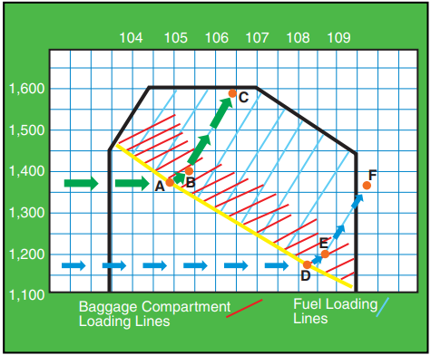
Figure 7-6. Loading chart illustrating the solution to sample problems 1 and 2.
To use the loading chart for the helicopter in this example, you must add up the items in a certain order. The maximum allowable gross weight is 1,600 pounds.
| ITEM | POUNDS |
| Basic empty weight | 1,040 |
| Pilot | 135 |
| Passenger | 200 |
| Subtotal | 1,375 (point A) |
| Baggage compartment load | 25 |
| Subtotal | 1,400 (point B) |
| Fuel load (30 gallons) | 180 |
| Total weight | 1,580 (point C) |
- Follow the green arrows in figure 7-6. Enter the graph on the left side at 1,375 lb., the subtotal of the empty weight and the passenger weight. Move right to the yellow line. (point A)
- Move up and to the right, parallel to the baggage compartment loading lines to 1,400 lb. (Point B)
- Continue up and to the right, this time parallel to the fuel loading lines, to the total weight of 1,580 lb. (Point C).
Point C is within allowable weight and CG limits.
SAMPLE PROBLEM 2
Assume that the pilot in sample problem 1 discharges the passenger after using only 20 pounds of fuel.
ITEM POUNDS
Basic empty weight 1,040
Pilot 135
Subtotal 1,175 (point D)
Baggage compartment load 25
Subtotal 1,200 (point E)
Fuel load 160
Total weight 1,360 (point F)
Follow the blue arrows in figure 7-6, starting at 1,175 lb. on the left side of the graph, then to point D, E, and
F. Although the total weight of the helicopter is well below the maximum allowable gross weight, point F falls outside the aft allowable CG limit.
As you can see, it is important to reevaluate the balance in a helicopter whenever you change the loading. Unlike most airplanes, where discharging a passenger is unlikely to adversely affect the CG, off-loading a passenger from a helicopter could make the aircraft unsafe to fly. Another difference between helicopter and air- plane loading is that most small airplanes carry fuel in the wings very near the center of gravity. Burning off fuel has little effect on the loaded CG. However, helicopter fuel tanks are often significantly behind the center of gravity. Consuming fuel from a tank aft of the rotor mast causes the loaded helicopter CG to move forward. As standard practice, you should compute the weight and balance with zero fuel to verify that your helicopter remains within the acceptable limits as fuel is used.
SAMPLE PROBLEM 3
The loading chart used in the sample problems 1 and 2 is designed to graphically calculate the loaded center of gravity and show whether it is within limits, all on a single chart. Another type of loading chart calculates moments for each station. You must then add up these moments and consult another graph to determine whether the total is within limits. Although this method has more steps, the charts are sometimes easier to use.
To begin, record the basic empty weight of the helicopter, along with its total moment. Remember to use the actual weight and moment of the helicopter you are flying. Next, record the weights of the pilot, passengers, fuel, and baggage on a weight and balance worksheet. Then, determine the total weight of the helicopter. Once you have determined the weight to be within pre- scribed limits, compute the moment for each weight and for the loaded helicopter. Do this with a loading graph provided by the manufacturer. Use figure 7-7 to determine the moments for a pilot and passenger weighing 340 pounds and for 211 pounds of fuel.
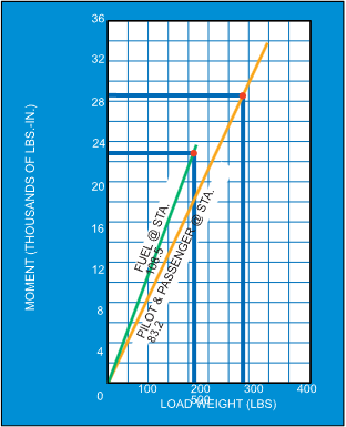
Figure 7-7. Moments for fuel, pilot, and passenger.
Start at the bottom scale labeled LOAD WEIGHT. Draw a line from 211 pounds up to the line labeled “FUEL @ STA108.5.” Draw your line to the left to intersect the MOMENT scale and read the fuel moment (22.9 thousand lb.-inches). Do the same for the pilot/passenger moment. Draw a line from a weight of 340 pounds up to the line labeled “PILOT & PASSENGER @STA. 83.2.” Go left and read the pilot/passenger moment (28.3 thousand lb.-inches).
Reduction factors are often used to reduce the size of large numbers to manageable levels. In figure 7-7, the scale on the loading graph gives you moments in thou- sands of pound-inches. In most cases, when using this type of chart, you need not be concerned with reduction factors because the CG/moment envelope chart normally uses the same reduction factor. [Figure 7-8]
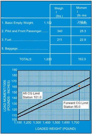
Figure 7-8. CG/Moment Chart.
After recording the basic empty weight and moment of the helicopter, and the weight and moment for each item, total and record all weights and moments. Next, plot the calculated takeoff weight and moment on the sample moment envelope graph. Based on a weight of 1,653 pounds and a moment/1,000 of 162 pound-inches, the helicopter is within the prescribed CG limits.
COMBINATION METHOD
The combination method usually uses the computation method to determine the moments and center of gravity. Then, these figures are plotted on a graph to determine if they intersect within the acceptable envelope. Figure 7-9 illustrates that with a total weight of 2,399 pounds and a total moment of 225,022 pound-
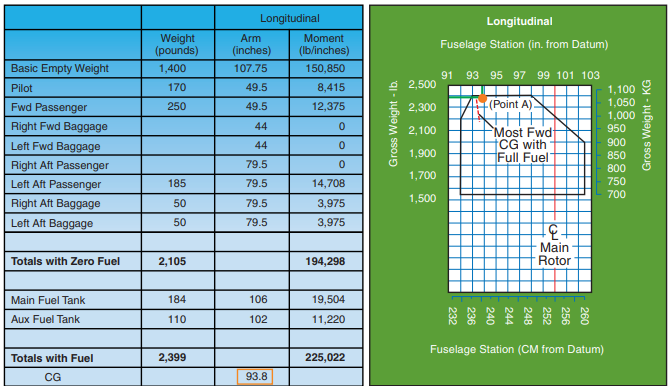
Figure 7-9. Use the longitudinal CG envelope along with the computed CGs to determine if the helicopter is loaded properly.
inches, the CG is 93.8. Plotting this CG against the weight indicates that the helicopter is loaded within the longitudinal limits (point A).
CALCULATING LATERAL CG
Some helicopter manufacturers require that you also determine the lateral CG limits. These calculations are similar to longitudinal calculations. However, since the lateral CG datum line is almost always defined as the center of the helicopter, you are likely to encounter negative CGs and moments in your calculations.
Negative values are located on the left side while posi- tive stations are located on the right.
Refer to figure 7-10. When computing moment for the pilot, 170 pounds is multiplied by the arm of 12.2 inches resulting in a moment of 2,074 pound-inches. As with any weight placed right of the aircraft centerline, the moment is expressed as a positive value. The forward passenger sits left of the aircraft centerline. To compute this moment, multiply 250 pounds by –10.4 inches. The result is in a moment of –2,600 pound-inches. Once the aircraft is completely loaded, the weights and moments are totaled and the CG is computed. Since more weight is located left of the aircraft centerline, the resulting total moment is –3,837 pound-inches. To calculate CG, divide –3,837 pound-inches by the total weight of 2,399 pounds. The result is –1.6 inches, or a CG that is 1.6 inches left of the aircraft centerline.
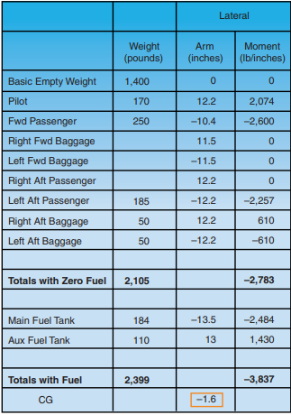
Figure 7-10. Computed Lateral CG.
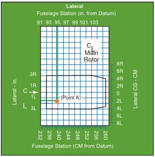
Figure 7-11. Use the lateral CG envelope to determine if the helicopter is properly loaded.
Lateral CG is often plotted against the longitudinal CG. [Figure 7-11] In this case, –1.6 is plotted against 93.8, which was the longitudinal CG determined in the previous problem. The intersection of the two lines falls well within the lateral CG envelope.


