By knowing the various systems on a helicopter, you will be able to more easily recognize potential problems, and if a problem arises, you will have a better under- standing of what to do to correct the situation.
Engines
The two most common types of engines used in helicopters are the reciprocating engine and the turbine engine. Reciprocating engines, also called piston engines, are generally used in smaller helicopters. Most training helicopters use reciprocating engines because they are relatively simple and inexpensive to operate. Turbine engines are more powerful and are used in a wide variety of helicopters. They produce a tremendous amount of power for their size but are generally more expensive to operate.
RECIPROCATING ENGINE
The reciprocating engine consists of a series of pistons connected to a rotating crankshaft. As the pistons move up and down, the crankshaft rotates. The reciprocating engine gets its name from the back-and-forth movement of its internal parts. The four-stroke engine is the most common type, and refers to the four different cycles the engine undergoes to produce power. [Figure 5-1]
When the piston moves away from the cylinder head on the intake stroke, the intake valve opens and a mixture of fuel and air is drawn into the combustion chamber. As the cylinder moves back towards the cylinder head, the intake valve closes, and the fuel/air mixture is com- pressed. When compression is nearly complete, the spark plugs fire and the compressed mixture is ignited to begin the power stroke. The rapidly expanding gases from the controlled burning of the fuel/air mixture drive the piston away from the cylinder head, thus pro- viding power to rotate the crankshaft. The piston then moves back toward the cylinder head on the exhaust stroke where the burned gasses are expelled through the opened exhaust valve.
Even when the engine is operated at a fairly low speed, the four-stroke cycle takes place several hundred times each minute. In a four-cylinder engine, each cylinder operates on a different stroke. Continuous rotation of a crankshaft is maintained by the precise timing of the power strokes in each cylinder.
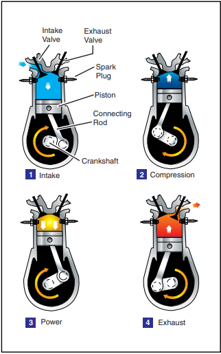
Figure 5-1. The arrows in this illustration indicate the direction of motion of the crankshaft and piston during the four- stroke cycle.
TURBINE ENGINE
The gas turbine engine mounted on most helicopters is made up of a compressor, combustion chamber, turbine, and gearbox assembly. The compressor compresses the air, which is then fed into the combustion chamber where atomized fuel is injected into it. The fuel/air mixture is ignited and allowed to expand. This combustion gas is then forced through a series of turbine wheels causing them to turn. These turbine wheels provide power to both the engine compressor and the main rotor system through an output shaft. The
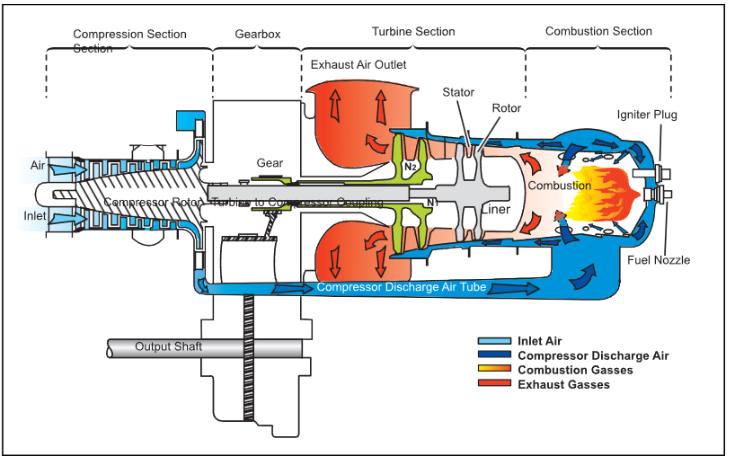
Figure 5-2. Many helicopters use a turboshaft engine to drive the main transmission and rotor systems. The main difference between a turboshaft and a turbojet engine is that most of the energy produced by the expanding gases is used to drive a tur- bine rather than producing thrust through the expulsion of exhaust gases.
combustion gas is finally expelled through an exhaust outlet. [Figure 5-2]
COMPRESSOR
The compressor may consist of an axial compressor, a centrifugal compressor, or both. An axial compressor consists of two main elements, the rotor and the stator. The rotor consists of a number of blades fixed on a rotating spindle and resembles a fan. As the rotor turns, air is drawn rearwards. Stator vanes are arranged in fixed rows between the rotor blades and act as a diffuser at each stage to decrease air velocity and increase air pressure. There may be a number of rows of rotor blades and stator vanes. Each row constitutes a pressure stage, and the number of stages depends on the amount of air and pressure rise required for the particular engine.
A centrifugal compressor consists of an impeller, diffuser, and a manifold. The impeller, which is a forged disc with integral blades, rotates at a high speed to draw air in and expel it at an accelerated rate. The air then passes through the diffuser which slows the air down. When the velocity of the air is slowed, static pressure increases, resulting in compressed, high-pressure air. The high pressure air then passes through the compressor manifold where it is distributed to the combustion chamber.
COMBUSTION CHAMBER
Unlike a piston engine, the combustion in a turbine engine is continuous. An igniter plug serves only to ignite the fuel/air mixture when starting the engine. Once the fuel/air mixture is ignited, it will continue to burn as long as the fuel/air mixture continues to be present. If there is an interruption of fuel, air, or both, combustion ceases. This is known as a “flame-out,” and the engine has to be restarted or re-lit. Some helicopters are equipped with auto-relight, which automatically activates the igniters to start combustion if the engine flames out.
TURBINE
The turbine section consists of a series of turbine wheels that are used to drive the compressor section and the rotor system. The first stage, which is usually referred to as the gas producer or N1 may consist of one or more turbine wheels. This stage drives the components necessary to complete the turbine cycle making the engine self-sustaining. Common components driven by the N1 stage are the compressor, oil pump, and fuel pump. The second stage, which may also consist of one or more wheels, is dedicated to driving the main rotor system and accessories from the engine gearbox. This is referred to as the power turbine (N2 or Nr).
If the first and second stage turbines are mechanically cou- pled to each other, the system is said to be a direct-drive engine or fixed turbine. These engines share a common shaft, which means the first and second stage turbines, and thus the compressor and output shaft, are connected.
On most turbine assemblies used in helicopters, the first stage and second stage turbines are not mechanically connected to each other. Rather, they are mounted on independent shafts and can turn freely with respect to each other. This is referred to as a “free turbine.” When the engine is running, the combustion gases pass through the first stage turbine to drive the compressor rotor, and then past the independent second stage tur- bine, which turns the gearbox to drive the output shaft.
Transmission system
The transmission system transfers power from the engine to the main rotor, tail rotor, and other accessories. The main components of the transmission system are the main rotor transmission, tail rotor drive system, clutch, and freewheeling unit. Helicopter trans- missions are normally lubricated and cooled with their own oil supply. A sight gauge is provided to check the oil level. Some transmissions have chip detectors located in the sump. These detectors are wired to warning lights located on the pilot’s instrument panel that illuminate in the event of an internal problem.
MAIN ROTOR TRANSMISSION
The primary purpose of the main rotor transmission is to reduce engine output r.p.m. to optimum rotor
r.p.m. This reduction is different for the various heli- copters, but as an example, suppose the engine r.p.m. of a specific helicopter is 2,700. To achieve a rotor speed of 450 r.p.m. would require a 6 to 1 reduction. A 9 to 1 reduction would mean the rotor would turn at 300 r.p.m.
Most helicopters use a dual-needle tachometer to show both engine and rotor r.p.m. or a percentage of engine and rotor r.p.m. The rotor r.p.m. needle normally is used only during clutch engagement to monitor rotor acceleration, and in autorotation to maintain r.p.m. within prescribed limits. [Figure 5-3]
Chip Detector—A chip detector is a warning device that alerts you to any abnormal wear in a transmission or engine. It consists of a magnetic plug located within the transmission. The magnet attracts any ferrous metal particles that have come loose from the bearings or other transmission parts. Most chip detectors send a signal to lights located on the instrument panel that illuminate when ferrous metal particles are picked up.
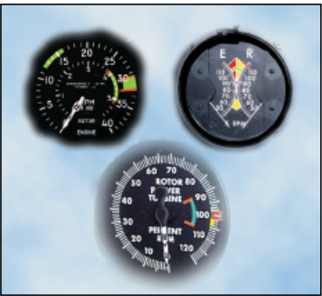
Figure 5-3. There are various types of dual-needle tachome- ters, however, when the needles are superimposed or married, the ratio of the engine r.p.m. is the same as the gear reduction ratio.
In helicopters with horizontally mounted engines, another purpose of the main rotor transmission is to change the axis of rotation from the horizontal axis of the engine to the vertical axis of the rotor shaft.
TAIL ROTOR DRIVE SYSTEM
The tail rotor drive system consists of a tail rotor drive shaft powered from the main transmission and a tail rotor transmission mounted at the end of the tail boom. The drive shaft may consist of one long shaft or a series of shorter shafts connected at both ends with flexible couplings. This allows the drive shaft to flex with the tail boom. The tail rotor transmission provides a right angle drive for the tail rotor and may also include gearing to adjust the output to optimum tail rotor r.p.m. [Figure 5-4]
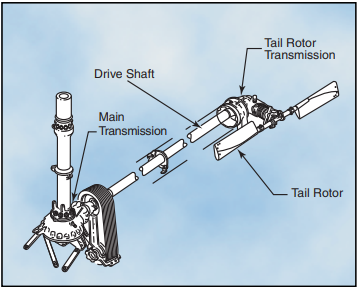
Figure 5-4. The typical components of a tail rotor drive system are shown here.
CLUTCH
In a conventional airplane, the engine and propeller are permanently connected. However, in a helicopter there is a different relationship between the engine and the rotor. Because of the greater weight of a rotor in rela- tion to the power of the engine, as compared to the weight of a propeller and the power in an airplane, the rotor must be disconnected from the engine when you engage the starter. A clutch allows the engine to be started and then gradually pick up the load of the rotor.
On free turbine engines, no clutch is required, as the gas producer turbine is essentially disconnected from the power turbine. When the engine is started, there is little resistance from the power turbine. This enables the gas producer turbine to accelerate to normal idle speed without the load of the transmission and rotor system dragging it down. As the gas pressure increases through the power turbine, the rotor blades begin to turn, slowly at first and then gradually accelerate to normal operating r.p.m.
On reciprocating helicopters, the two main types of clutches are the centrifugal clutch and the belt drive clutch.
CENTRIFUGAL CLUTCH
The centrifugal clutch is made up of an inner assembly and a outer drum. The inner assembly, which is con- nected to the engine driveshaft, consists of shoes lined with material similar to automotive brake linings. At low engine speeds, springs hold the shoes in, so there is no contact with the outer drum, which is attached to the transmission input shaft. As engine speed increases, centrifugal force causes the clutch shoes to move out- ward and begin sliding against the outer drum. The transmission input shaft begins to rotate, causing the rotor to turn, slowly at first, but increasing as the friction increases between the clutch shoes and transmission drum. As rotor speed increases, the rotor tachometer needle shows an increase by moving toward the engine tachometer needle. When the two needles are superim- posed, the engine and the rotor are synchronized, indicating the clutch is fully engaged and there is no further slippage of the clutch shoes.
BELT DRIVE CLUTCH
Some helicopters utilize a belt drive to transmit power from the engine to the transmission. A belt drive con- sists of a lower pulley attached to the engine, an upper pulley attached to the transmission input shaft, a belt or a series of V-belts, and some means of applying tension to the belts. The belts fit loosely over the upper and lower pulley when there is no tension on the belts. This allows the engine to be started without any load from the transmission. Once the engine is running, tension on the belts is gradually increased. When the rotor and engine tachometer needles are superimposed, the rotor and the engine are synchronized, and the clutch is then fully engaged.
Advantages of this system include vibration isolation, simple maintenance, and the ability to start and warm up the engine without engaging the rotor.
FREEWHEELING UNIT
Since lift in a helicopter is provided by rotating airfoils, these airfoils must be free to rotate if the engine fails. The freewheeling unit automatically disengages the engine from the main rotor when engine r.p.m. is less than main rotor r.p.m. This allows the main rotor to continue turning at normal in-flight speeds. The most common freewheel- ing unit assembly consists of a one-way sprag clutch located between the engine and main rotor transmission. This is usually in the upper pulley in a piston helicopter or mounted on the engine gearbox in a turbine helicopter. When the engine is driving the rotor, inclined surfaces in the spray clutch force rollers against an outer drum. This prevents the engine from exceeding transmission r.p.m. If the engine fails, the rollers move inward, allowing the outer drum to exceed the speed of the inner portion. The transmission can then exceed the speed of the engine. In this condition, engine speed is less than that of the drive system, and the helicopter is in an autorotative state.
Main rotor system
Main rotor systems are classified according to how the main rotor blades move relative to the main rotor hub. As was described in Chapter 1—Introduction to the Helicopter, there are three basic classifications: fully articulated, semirigid, or rigid. Some modern rotor systems use a combination of these types.
FULLY ARTICULATED ROTOR SYSTEM
In a fully articulated rotor system, each rotor blade is attached to the rotor hub through a series of hinges, which allow the blade to move independently of the others. These rotor systems usually have three or more blades. [Figure 5-5]
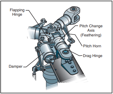
Figure 5-5. Each blade of a fully articulated rotor system can flap, drag, and feather independently of the other blades.
The horizontal hinge, called the flapping hinge, allows the blade to move up and down. This movement is called flapping and is designed to compensate for dis- symetry of lift. The flapping hinge may be located at varying distances from the rotor hub, and there may be more than one hinge.
The vertical hinge, called the lead-lag or drag hinge, allows the blade to move back and forth. This move- ment is called lead-lag, dragging, or hunting. Dampers are usually used to prevent excess back and forth movement around the drag hinge. The pur- pose of the drag hinge and dampers is to compensate for the acceleration and deceleration caused by Coriolis Effect.
Each blade can also be feathered, that is, rotated around its spanwise axis. Feathering the blade means changing the pitch angle of the blade. By changing the pitch angle of the blades you can control the thrust and direction of the main rotor disc.
SEMIRIGID ROTOR SYSTEM
A semirigid rotor system is usually composed of two blades which are rigidly mounted to the main rotor hub. The main rotor hub is free to tilt with respect to the main rotor shaft on what is known as a teetering hinge. This allows the blades to flap together as a unit. As one blade flaps up, the other flaps down. Since there is no vertical drag hinge, lead-lag forces are absorbed through blade bending. [Figure 5-6]
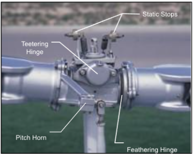
Figure 5-6. On a semirigid rotor system, a teetering hinge allows the rotor hub and blades to flap as a unit. A static flap- ping stop located above the hub prevents excess rocking when the blades are stopped. As the blades begin to turn, centrifugal force pulls the static stops out of the way.
RIGID ROTOR SYSTEM
In a rigid rotor system, the blades, hub, and mast are rigid with respect to each other. There are no vertical or horizontal hinges so the blades cannot flap or drag, but they can be feathered. Flapping and lead/lag forces are absorbed by blade bending.
COMBINATION ROTOR SYSTEMS
Modern rotor systems may use the combined principles of the rotor systems mentioned above. Some rotor hubs incorporate a flexible hub, which allows for blade bending (flexing) without the need for bearings or hinges. These systems, called flextures, are usually constructed from composite material. Elastomeric bearings may also be used in place of conventional roller bearings. Elastomeric bearings are bearings constructed from a rubber type material and have limited movement that is perfectly suited for helicopter applications. Flextures and elastomeric bearings require no lubrication and, therefore, require less maintenance. They also absorb vibration, which means less fatigue and longer service life for the helicopter components. [Figure 5-7]
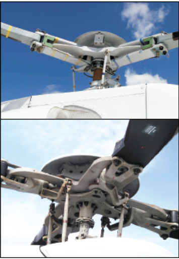
Figure 5-7. Rotor systems, such as Eurocopter’s Starflex or Bell’s soft-in-plane, use composite material and elastomeric bearings to reduce complexity and maintenance and, thereby, increase reliability.
SWASH PLATE ASSEMBLY
The purpose of the swash plate is to transmit control inputs from the collective and cyclic controls to the main rotor blades. It consists of two main parts: the stationary swash plate and the rotating swash plate. [Figure 5-8] The stationary swash plate is mounted around the main rotor mast and connected to the cyclic and collective controls by a series of pushrods. It is restrained from rotating but is able to tilt in all directions and move vertically. The rotating swash plate is mounted to the stationary swash plate by means of a bearing and is allowed to rotate with the main rotor mast. Both swash plates tilt and slide up and down as one unit. The rotating swash plate is connected to the pitch horns by the pitch links.
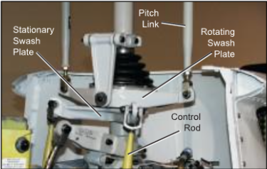
Figure 5-8. Collective and cyclic control inputs are transmit- ted to the stationary swash plate by control rods causing it to tilt or to slide vertically. The pitch links attached from the rotating swash plate to the pitch horns on the rotor hub transmit these movements to the blades.
Fuel systems
The fuel system in a helicopter is made up of two groups of components: the fuel supply system and the engine fuel control system.
FUEL SUPPLY SYSTEM
The supply system consists of a fuel tank or tanks, fuel quantity gauges, a shut-off valve, fuel filter, a fuel line to the engine, and possibly a primer and fuel pumps. [Figure 5-9]
The fuel tanks are usually mounted to the airframe as close as possible to the center of gravity. This way, as fuel is burned off, there is a negligible effect on the center of gravity. A drain valve located on the bottom of the fuel tank allows the pilot to drain water and sediment that may have collected in the tank. A fuel vent prevents the formation of a vacuum in the tank, and an overflow drain allows for fuel to expand without rupturing the tank. A fuel quantity gauge located on the pilot’s instrument panel shows the amount of fuel measured by a sensing unit inside the tank. Some gauges show tank capacity in both gallons and pounds.
The fuel travels from the fuel tank through a shut-off valve, which provides a means to completely stop fuel
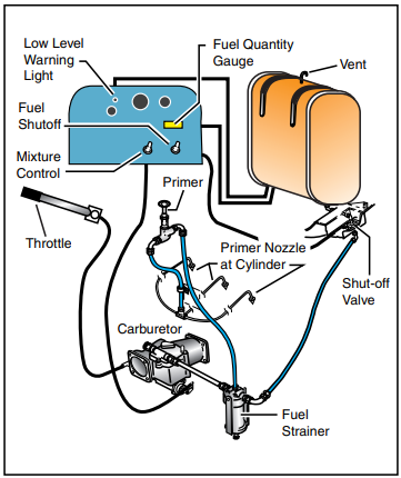
Figure 5-9. A typical gravity feed fuel system, in a helicopter with a reciprocating engine, contains the components shown here.
flow to the engine in the event of an emergency or fire. The shut-off valve remains in the open position for all normal operations.
Most non-gravity feed fuel systems contain both an electric pump and a mechanical engine driven pump. The electrical pump is used to maintain positive fuel pressure to the engine pump and also serves as a backup in the event of mechanical pump failure. The electrical pump is controlled by a switch in the cockpit. The engine driven pump is the primary pump that sup- plies fuel to the engine and operates any time the engine is running.
A fuel filter removes moisture and other sediment from the fuel before it reaches the engine. These contaminants are usually heavier than fuel and settle to the bot- tom of the fuel filter sump where they can be drained out by the pilot.
Some fuel systems contain a small hand-operated pump called a primer. A primer allows fuel to be pumped directly into the intake port of the cylinders prior to engine start. The primer is useful in cold weather when fuel in the carburetor is difficult to vaporize.
ENGINE FUEL CONTROL SYSTEM
The purpose of the fuel control system is to bring out- side air into the engine, mix it with fuel in the proper proportion, and deliver it to the combustion chamber.
RECIPROCATING ENGINES
Fuel is delivered to the cylinders by either a carburetor or fuel injection system.
CARBURETOR
In a carburetor system, air is mixed with vaporized fuel as it passes through a venturi in the carburetor. The metered fuel/air mixture is then delivered to the cylinder intake.
Carburetors are calibrated at sea level, and the correct fuel-to-air mixture ratio is established at that altitude with the mixture control set in the FULL RICH position. However, as altitude increases, the density of air entering the carburetor decreases while the density of the fuel remains the same. This means that at higher altitudes, the mixture becomes progressively richer. To maintain the correct fuel/air mixture, you must be able to adjust the amount of fuel that is mixed with the incoming air. This is the function of the mixture control. This adjustment, often referred to as “leaning the mixture,” varies from one aircraft to another. Refer to the FAA-Approved Rotocraft Flight Manual (RFM) to determine specific procedures for your helicopter. Note that most manufacturers do not recommend leaning helicopters in-flight.
Most mixture adjustments are required during changes of altitude or during operations at airports with field elevations well above sea level. A mixture that is too rich can result in engine roughness and reduced power. The rough- ness normally is due to spark plug fouling from excessive carbon buildup on the plugs. This occurs because the excessively rich mixture lowers the temperature inside the cylinder, inhibiting complete combustion of the fuel. This condition may occur during the pretakeoff runup at high elevation airports and during climbs or cruise flight at high altitudes. Usually, you can correct the problem by leaning the mixture according to RFM instructions.
If you fail to enrich the mixture during a descent from high altitude, it normally becomes too lean. High engine temperatures can cause excessive engine wear or even failure. The best way to avoid this type of situation is to monitor the engine temperature gauges regularly and follow the manufacturer’s guidelines for maintaining the proper mixture.
CARBURETOR ICE
The effect of fuel vaporization and decreasing air pressure in the venturi causes a sharp drop in temperature in the carburetor. If the air is moist, the water vapor in the air may condense. When the temperature in the carburetor is at or below freezing, carburetor ice may form on internal surfaces, including the throttle valve. [Figure 5-10] Because of the sudden cooling that takes place in the carburetor, icing can occur even on warm days with temperatures as high as 38°C (100°F) and the humidity as low as 50 percent. However, it is more likely to occur when temperatures are below 21°C (70°F) and the relative humidity is above 80 percent. The likelihood of icing increases as temperature decreases down to 0°C (32°F), and as relative humidity increases. Below freezing, the possibility of carburetor icing decreases with decreasing temperatures.
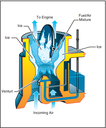
Figure 5-10. Carburetor ice reduces the size of the air pas- sage to the engine. This restricts the flow of the fuel/air mixture, and reduces power.
Although carburetor ice can occur during any phase of flight, it is particularly dangerous when you are using reduced power, such as during a descent. You may not notice it during the descent until you try to add power.
Indications of carburetor icing are a decrease in engine r.p.m. or manifold pressure, the carburetor air temperature gauge indicating a temperature outside the safe operating range, and engine roughness. Since changes in r.p.m. or manifold pressure can occur for a number of reasons, it is best to closely check the carburetor air temperature gauge when in possible carburetor icing conditions. Carburetor air temperature gauges are marked with a yellow caution arc or green operating arcs. You should refer to the FAA-Approved Rotorcraft Flight Manual for the specific procedure as to when and how to apply carburetor heat. However, in most cases, you should keep the needle out of the yellow arc or in the green arc. This is accomplished by using a carburetor heat system, which eliminates the ice by routing air across a heat source, such as an exhaust manifold, before it enters the carburetor. [Figure 5-11].
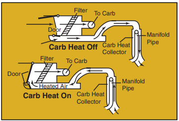
Figure 5-11. When you turn the carburetor heat ON, normal air flow is blocked, and heated air from an alternate source flows through the filter to the carburetor.
FUEL INJECTION
In a fuel injection system, fuel and air are metered at the fuel control unit but are not mixed. The fuel is injected directly into the intake port of the cylinder where it is mixed with the air just before entering the cylinder. This system ensures a more even fuel distribution in the cylinders and better vaporization, which in turn, promotes more efficient use of fuel. Also, the fuel injection system eliminates the problem of carburetor icing and the need for a carburetor heat system.
TURBINE ENGINES
The fuel control system on the turbine engine is fairly complex, as it monitors and adjusts many different parameters on the engine. These adjustments are done automatically and no action is required of the pilot other than starting and shutting down. No mixture adjustment is necessary, and operation is fairly simple as far as the pilot is concerned. New generation fuel controls incorporate the use of a full authority digital engine control (FADEC) computer to control the engine’s fuel requirements. The FADEC systems increase efficiency, reduce engine wear, and also reduce pilot workload. The FADEC usually incorporates back-up systems in the event of computer failure.
Electrical systems
The electrical systems, in most helicopters, reflect the increased use of sophisticated avionics and other electrical accessories. More and more operations in today’s flight environment are dependent on the aircraft’s electrical system; however, all helicopters can be safely flown without any electrical power in the event of an electrical malfunction or emergency.
Helicopters have either a 14- or 28-volt, direct-cur- rent electrical system. On small, piston powered helicopters, electrical energy is supplied by an enginedriven alternator. These alternators have advantages over older style generators as they are lighter in weight, require lower maintenance, and maintain a uniform electrical output even at low engine r.p.m. [Figure 5-12]
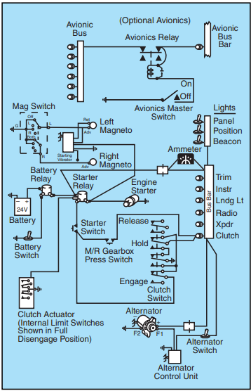
Figure 5-12. An electrical system scematic like this sample is included in most POHs. Notice that the various bus bar accessories are protected by circuit breakers. However, you should still make sure all electrical equipment is turned off before you start the engine. This protects sensitive components, particularly the radios, from damage which may be caused by random voltages generated during the starting process.
Turbine powered helicopters use a starter/generator system. The starter/generator is permanently coupled to the engine gearbox. When starting the engine, electrical power from the battery is supplied to the starter/generator, which turns the engine over. Once the engine is running, the starter/generator is driven by the engine and is then used as a generator.
Current from the alternator or generator is delivered through a voltage regulator to a bus bar. The voltage regulator maintains the constant voltage required by the electrical system by regulating the output of the alternator or generator. An over-voltage control may be incorporated to prevent excessive voltage, which may damage the electrical components. The bus bar serves to distribute the current to the various electrical com- ponents of the helicopter.
A battery is mainly used for starting the engine. In addition, it permits limited operation of electrical components, such as radios and lights, without the engine running. The battery is also a valuable source of standby or emergency electrical power in the event of alternator or generator failure.
An ammeter or loadmeter is used to monitor the electrical current within the system. The ammeter reflects current flowing to and from the battery. A charging ammeter indicates that the battery is being charged. This is normal after an engine start since the battery power used in starting is being replaced. After the battery is charged, the ammeter should stabilize near zero since the alternator or generator is supplying the electrical needs of the system. A dis- charging ammeter means the electrical load is exceeding the output of the alternator or generator, and the battery is helping to supply electrical power. This may mean the alternator or generator is mal- functioning, or the electrical load is excessive. A loadmeter displays the load placed on the alternator or generator by the electrical equipment. The RFM for a particular helicopter shows the normal load to expect. Loss of the alternator or generator causes the loadmeter to indicate zero.
Electrical switches are used to select electrical compo- nents. Power may be supplied directly to the component or to a relay, which in turn provides power to the component. Relays are used when high current and/or heavy electrical cables are required for a particular com- ponent, which may exceed the capacity of the switch.
Circuit breakers or fuses are used to protect various electrical components from overload. A circuit breaker pops out when its respective component is overloaded. The circuit breaker may be reset by pushing it back in, unless a short or the overload still exists. In this case, the circuit breaker continues to pop, indicating an electrical malfunction. A fuse simply burns out when it is overloaded and needs to be replaced. Manufacturers usually provide a holder for spare fuses in the event one has to be replaced in flight. Caution lights on the instru- ment panel may be installed to show the malfunction of an electrical component.
Hydraulics
Most helicopters, other than smaller piston powered helicopters, incorporate the use of hydraulic actuators to overcome high control forces. [Figure 5-13] A typical hydraulic system consists of actuators, also called
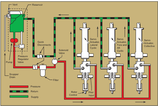
Figure 5-13. A typical hydraulic system for helicopters in the light to medium range is shown here.
servos, on each flight control, a pump which is usually driven by the main rotor gearbox, and a reservoir to store the hydraulic fluid. A switch in the cockpit can turn the system off, although it is left on under normal conditions. A pressure indicator in the cockpit may also be installed to monitor the system.
When you make a control input, the servo is activated and provides an assisting force to move the respective flight control, thus lightening the force required by the pilot. These boosted flight controls ease pilot workload and fatigue. In the event of hydraulic system failure, you are still able to control the helicopter, but the control forces will be very heavy.
In those helicopters where the control forces are so high that they cannot be moved without hydraulic assistance, two or more independent hydraulic systems may be installed. Some helicopters use hydraulic accumulators to store pressure, which can be used for a short period of time in an emergency if the hydraulic pump fails. This gives you enough time to land the helicopter with normal control
Stability augmentations systems
Some helicopters incorporate stability augmentations systems (SAS) to aid in stabilizing the helicopter in flight and in a hover. The simplest of these systems is a force trim system, which uses a magnetic clutch and springs to hold the cyclic control in the position where it was released. More advanced systems use electric servos that actually move the flight controls. These servos receive control commands from a computer that senses helicopter attitude. Other inputs, such as heading, speed, altitude, and navigation information may be supplied to the computer to form a complete autopilot system. The SAS may be overridden or disconnected by the pilot at any time.
Stability augmentation systems reduce pilot workload by improving basic aircraft control harmony and decreasing disturbances. These systems are very useful when you are required to perform other duties, such as sling loading and search and rescue operations.
Autopilot
Helicopter autopilot systems are similar to stability augmentations systems except they have additional features. An autopilot can actually fly the helicopter and perform certain functions selected by the pilot. These functions depend on the type of autopilot and systems installed in the helicopter.
The most common functions are altitude and heading hold. Some more advanced systems include a vertical speed or indicated airspeed (IAS) hold mode, where a constant rate of climb/descent or indicated airspeed is maintained by the autopilot. Some autopilots have navigation capabilities, such as VOR, ILS, and GPS intercept and tracking, which is especially useful in IFR conditions. The most advanced autopilots can fly an instrument approach to a hover without any additional pilot input once the initial functions have been selected.
The autopilot system consists of electric actuators or servos connected to the flight controls. The number and location of these servos depends on the type of system installed. A two-axis autopilot controls the helicopter in pitch and roll; one servo controls fore and aft cyclic, and another controls left and right cyclic. A three-axis autopilot has an additional servo connected to the anti- torque pedals and controls the helicopter in yaw. A four-axis system uses a fourth servo which controls the collective. These servos move the respective flight controls when they receive control commands from a central computer. This computer receives data input from the flight instruments for attitude reference and from the navigation equipment for navigation and tracking reference. An autopilot has a control panel in the cock- pit that allows you to select the desired functions, as well as engage the autopilot.
For safety purposes, an automatic disengage feature is usually included which automatically disconnects the autopilot in heavy turbulence or when extreme flight attitudes are reached. Even though all autopilots can be overridden by the pilot, there is also an autopilot disengage button located on the cyclic or collective which allows you to completely disengage the autopilot with- out removing your hands from the controls. Because autopilot systems and installations differ from one helicopter to another, it is very important that you refer to the autopilot operating procedures located in the Rotorcraft Flight Manual.
Environmental systems
Heating and cooling for the helicopter cabin can be provided in different ways. The simplest form of cooling is ram air cooling. Air ducts in the front or sides of the helicopter are opened or closed by the pilot to let ram air into the cabin. This system is limited as it requires forward airspeed to provide airflow and also
VOR—Ground-based navigation system consisting of very high frequency omnidirectional range (VOR) stations which provide course guidance.
ILS (Instrument Landing System)—A precision instrument approach system, which normally consists of the following electronic components and visual aids: localizer, glide slope, outer marker, and approach lights.
GPS (Global Positioning System)—A satellite-based radio positioning, navigation, and time-transfer system.
IFR (Instrument Flight Rules)—Rules that govern the procedure for conducting flight in weather conditions below VFR weather minimums. The term IFR also is used to define weather conditions and the type of flight plan under which an aircraft is operating.
depends on the temperature of the outside air. Air conditioning provides better cooling but it is more com- plex and weighs more than a ram air system.
Piston powered helicopters use a heat exchanger shroud around the exhaust manifold to provide cabin heat. Outside air is piped to the shroud and the hot exhaust manifold heats the air, which is then blown into the cockpit. This warm air is heated by the exhaust manifold but is not exhaust gas. Turbine helicopters use a bleed air system for heat. Bleed air is hot, com- pressed, discharge air from the engine compressor. Hot air is ducted from the compressor to the helicopter cabin through a pilot-controlled, bleed air valve.
Anti-icing systems
Most anti-icing equipment installed on small helicopters is limited to engine intake anti-ice and pitot heat systems. The anti-icing system found on most turbine-powered helicopters uses engine bleed air. The bleed air flows through the inlet guide vanes to prevent ice formation on the hollow vanes. A pilot-controlled, electrically operated valve on the compressor controls the air flow. The pitot heat system uses an electrical element to heat the pitot tube, thus melting or preventing ice formation.
Airframe and rotor anti-icing may be found on some larger helicopters, but it is not common due to the complexity, expense, and weight of such systems. The leading edges of rotors may be heated with bleed air or electrical elements to prevent ice formation. Balance and control problems might arise if ice is allowed to form unevenly on the blades. Research is being done on lightweight ice-phobic (anti-icing) materials or coatings. These materials placed in strategic areas could significantly reduce ice formation and improve performance.


