There are four forces acting on a helicopter in flight. They are lift, weight, thrust, and drag. [Figure 2-1] Lift is the upward force created by the effect of airflow as it passes around an airfoil. Weight opposes lift and is caused by the downward pull of gravity. Thrust is the force that propels the helicopter through the air. Opposing lift and thrust is drag, which is the retarding force created by development of lift and the movement of an object through the air.
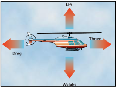
Figure 2-1. Four forces acting on a helicopter in forward flight.
Airfoil
Before beginning the discussion of lift, you need to be aware of certain aerodynamic terms that describe an airfoil and the interaction of the airflow around it.
An airfoil is any surface, such as an airplane wing or a helicopter rotor blade, which provides aerodynamic force when it interacts with a moving stream of air. Although there are many different rotor blade airfoil designs, in most helicopter flight conditions, all airfoils perform in the same manner.
Engineers of the first helicopters designed relatively thick airfoils for their structural characteristics. Because the rotor blades were very long and slender, it was necessary to incorporate more structural rigidity into them. This prevented excessive blade droop when the rotor system was idle, and minimized blade twisting while in flight. The airfoils were also designed to be symmetrical, which means they had the same camber (curvature) on both the upper and lower surfaces.
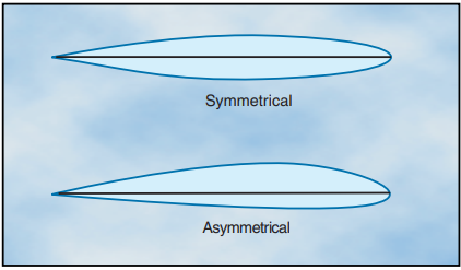
Figure 2-2. The upper and lower curvatures are the same on a symmetrical airfoil and vary on an asymmetrical airfoil.
Symmetrical blades are very stable, which helps keep blade twisting and flight control loads to a minimum. [Figure 2-2] This stability is achieved by keeping the center of pressure virtually unchanged as the angle of attack changes. Center of pressure is the imaginary point on the chord line where the resultant of all aero- dynamic forces are considered to be concentrated.
Today, designers use thinner airfoils and obtain the required rigidity by using composite materials. In addi- tion, airfoils are asymmetrical in design, meaning the upper and lower surface do not have the same camber. Normally these airfoils would not be as stable, but this can be corrected by bending the trailing edge to produce the same characteristics as symmetrical airfoils. This is called “reflexing.” Using this type of rotor blade allows the rotor system to operate at higher forward speeds.
One of the reasons an asymmetrical rotor blade is not as stable is that the center of pressure changes with changes in angle of attack. When the center of pressure lifting force is behind the pivot point on a rotor blade, it tends to cause the rotor disc to pitch up. As the angle of attack increases, the center of pressure moves forward. If it moves ahead of the pivot point, the pitch of the rotor disc decreases. Since the angle of attack of the rotor blades is constantly changing during each cycle of rotation, the blades tend to flap, feather, lead, and lag to a greater degree.
When referring to an airfoil, the span is the distance from the rotor hub to the blade tip. Blade twist refers to a changing chord line from the blade root to the tip.
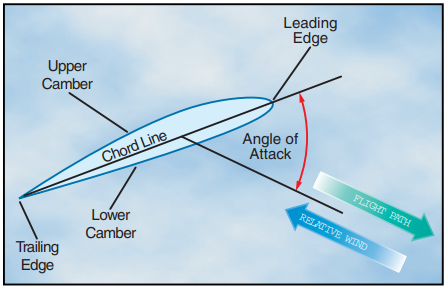
Figure 2-3. Aerodynamic terms of an airfoil.
Twisting a rotor blade causes it to produce a more even amount of lift along its span. This is necessary because rotational velocity increases toward the blade tip. The leading edge is the first part of the airfoil to meet the oncoming air. [Figure 2-3] The trailing edge is the aft portion where the airflow over the upper surface joins the airflow under the lower surface. The chord line is an imaginary straight line drawn from the leading to the trailing edge. The camber is the curvature of the air- foil’s upper and lower surfaces. The relative wind is the wind moving past the airfoil. The direction of this wind is relative to the attitude, or position, of the airfoil and is always parallel, equal, and opposite in direction to the flight path of the airfoil. The angle of attack is the angle between the blade chord line and the direction of the relative wind.
RELATIVE WIND
Relative wind is created by the motion of an airfoil through the air, by the motion of air past an airfoil, or by a combination of the two. Relative wind may be affected by several factors, including the rotation of the rotor blades, horizontal movement of the helicopter, flapping of the rotor blades, and wind speed and direction.
For a helicopter, the relative wind is the flow of air with respect to the rotor blades. If the rotor is stopped, wind blowing over the blades creates a relative wind. When the helicopter is hovering in a no-wind condition, relative wind is created by the motion of the rotor blades through the air. If the helicopter is hovering in a wind, the relative wind is a combination of the wind and the motion of the rotor blades through the air. When the helicopter is in forward flight, the relative wind is a combination of the rotation of the rotor blades and the forward speed of the helicopter.
BLADE PITCH ANGLE
The pitch angle of a rotor blade is the angle between its chord line and the reference plane containing the rotor hub. [Figure 2-4] You control the pitch angle of the blades with the flight controls. The collective pitch changes each rotor blade an equal amount of pitch no matter where it is located in the plane of rotation (rotor disc) and is used to change rotor thrust. The cyclic pitch control changes the pitch of each blade as a function of where it is in the plane of rotation. This allows for trimming the helicopter in pitch and roll during forward flight and for maneuvering in all flight conditions.
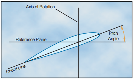
Figure 2-4. Do not confuse the axis of rotation with the rotor mast. The only time they coincide is when the tip-path plane is perpendicular to the rotor mast.
ANGLE OF ATTACK
When the angle of attack is increased, air flowing over the airfoil is diverted over a greater distance, resulting in an increase of air velocity and more lift. As angle of attack is increased further, it becomes more difficult for air to flow smoothly across the top of the airfoil. At this point the airflow begins to separate from the airfoil and enters a burbling or turbulent pattern. The turbulence results in a large increase in drag and loss of lift in the area where it is taking place. Increasing the angle of attack increases lift until the critical angle of attack is reached. Any increase in the angle of attack beyond this point produces a stall and a rapid decrease in lift. [Figure 2-5]
Angle of attack should not be confused with pitch angle. Pitch angle is determined by the direction of the relative wind. You can, however, change the angle of attack by changing the pitch angle through the use of the flight controls. If the pitch angle is increased, the angle of attack is increased, if the pitch angle is reduced, the angle of attack is reduced. [Figure 2-6]
Axis-of-Rotation—The imaginary line about which the rotor rotates. It is represented by a line drawn through the center of, and perpendicular to, the tip-path plane.
Tip-Path Plane—The imaginary circular plane outlined by the rotor blade tips as they make a cycle of rotation.
Aircraft Pitch—When referenced to a helicopter, is the movement of the helicopter about its lateral, or side to side axis. Movement of the cyclic forward or aft causes the nose of the helicopter to move up or down.
Aircraft Roll—Is the movement of the helicopter about its longitudinal, or nose to tail axis. Movement of the cyclic right or left causes the helicopter to tilt in that direction.
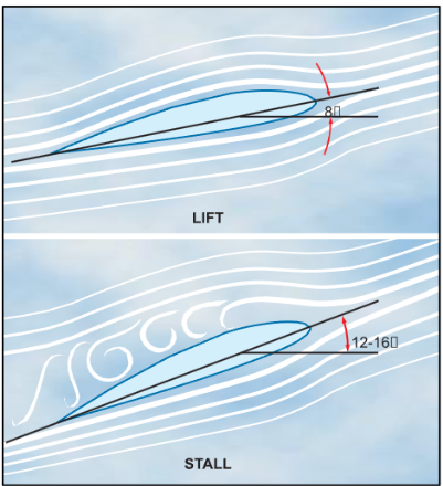
Figure 2-5. As the angle of attack is increased, the separation point starts near the trailing edge of the airfoil and pro- gresses forward. Finally, the airfoil loses its lift and a stall condition occurs.
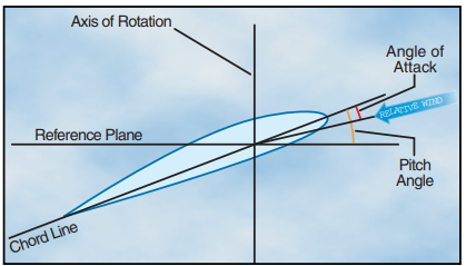
Figure 2-6. Angle of attack may be greater than, less than, or the same as the pitch angle
Lift
MAGNUS EFFECT
The explanation of lift can best be explained by looking at a cylinder rotating in an airstream. The local velocity near the cylinder is composed of the airstream velocity and the cylinder’s rotational velocity, which decreases with distance from the cylinder. On a cylinder, which is rotating in such a way that the top surface area is rotating in the same direction as the airflow, the local velocity at the surface is high on top and low on the bottom.
As shown in figure 2-7, at point “A,” a stagnation point exists where the airstream line that impinges on the sur- face splits; some air goes over and some under. Another stagnation point exists at “B,” where the two air streams rejoin and resume at identical velocities. We
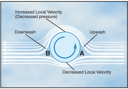
Figure 2-7. Magnus Effect is a lifting force produced when a rotating cylinder produces a pressure differential. This is the same effect that makes a baseball curve or a golf ball slice.
now have upwash ahead of the rotating cylinder and downwash at the rear.
The difference in surface velocity accounts for a differ- ence in pressure, with the pressure being lower on the top than the bottom. This low pressure area produces an upward force known as the “Magnus Effect.” This mechanically induced circulation illustrates the rela- tionship between circulation and lift.
An airfoil with a positive angle of attack develops air circulation as its sharp trailing edge forces the rear stagnation point to be aft of the trailing edge, while the front stagnation point is below the leading edge. [Figure 2-8]
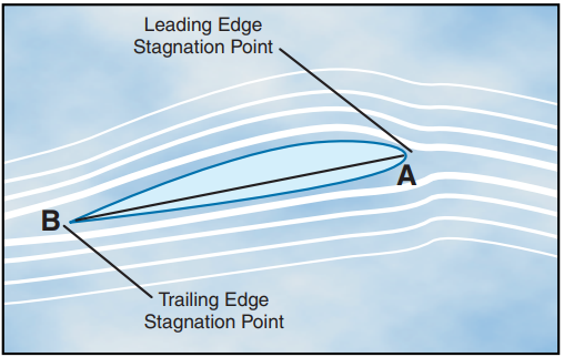
Figure 2-8. Air circulation around an airfoil occurs when the front stagnation point is below the leading edge and the aft stagnation point is beyond the trailing edge.
BERNOULLI’S PRINCIPLE
Air flowing over the top surface accelerates. The airfoil is now subjected to Bernoulli’s Principle or the “venturi effect.” As air velocity increases through the constricted portion of a venturi tube, the pressure decreases.
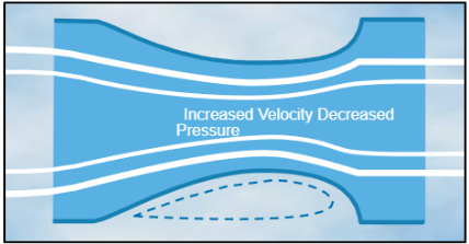
Figure 2-9. The upper surface of an airfoil is similar to the constriction in a venturi tube
Compare the upper surface of an airfoil with the con- striction in a venturi tube that is narrower in the middle than at the ends. [Figure 2-9]
The upper half of the venturi tube can be replaced by layers of undisturbed air. Thus, as air flows over the upper surface of an airfoil, the camber of the airfoil causes an increase in the speed of the airflow. The increased speed of airflow results in a decrease in pressure on the upper surface of the airfoil. At the same time, air flows along the lower surface of the airfoil, building up pressure. The combination of decreased pressure on the upper surface and increased pressure on the lower surface results in an upward force. [Figure 2-10]
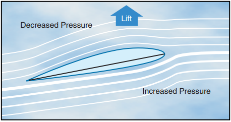
Figure 2-10. Lift is produced when there is decreased pres- sure above and increased pressure below an airfoil.
As angle of attack is increased, the production of lift is increased. More upwash is created ahead of the airfoil as the leading edge stagnation point moves under the leading edge, and more downwash is created aft of the trailing edge. Total lift now being produced is perpendicular to relative wind. In summary, the production of lift is based upon the airfoil creating circulation in the airstream (Magnus Effect) and creating differential pressure on the airfoil (Bernoulli’s Principle).
NEWTON’S THIRD LAW OF MOTION
Additional lift is provided by the rotor blade’s lower surface as air striking the underside is deflected downward. According to Newton’s Third Law of Motion, “for every action there is an equal and opposite reac- tion,” the air that is deflected downward also produces an upward (lifting) reaction.
Since air is much like water, the explanation for this source of lift may be compared to the planing effect of skis on water. The lift which supports the water skis (and the skier) is the force caused by the impact pres- sure and the deflection of water from the lower surfaces of the skis.
Under most flying conditions, the impact pressure and the deflection of air from the lower surface of the rotor blade provides a comparatively small percentage of the total lift. The majority of lift is the result of decreased pressure above the blade, rather than the increased pressure below it.
Weight
Normally, weight is thought of as being a known, fixed value, such as the weight of the helicopter, fuel, and occupants. To lift the helicopter off the ground verti- cally, the rotor system must generate enough lift to overcome or offset the total weight of the helicopter and its occupants. This is accomplished by increasing the pitch angle of the main rotor blades.
The weight of the helicopter can also be influenced by aerodynamic loads. When you bank a helicopter while maintaining a constant altitude, the “G” load or load factor increases. Load factor is the ratio of the load sup- ported by the main rotor system to the actual weight of the helicopter and its contents. In steady-state flight, the helicopter has a load factor of one, which means the main rotor system is supporting the actual total weight of the helicopter. If you increase the bank angle to 60°, while still maintaining a constant altitude, the load fac- tor increases to two. In this case, the main rotor system has to support twice the weight of the helicopter and its contents. [Figure 2-11]
Disc loading of a helicopter is the ratio of weight to the total main rotor disc area, and is determined by dividing the total helicopter weight by the rotor disc area, which is the area swept by the blades of a rotor. Disc area can be found by using the span of one rotor blade as the radius of a circle and then determining the area the blades encompass during a complete rotation. As the helicopter is maneuvered, disc loading changes. The higher the loading, the more power you need to maintain rotor speed.
Steady-State Flight—A condition when an aircraft is in straight and-level, unaccelerated flight, and all forces are in balance
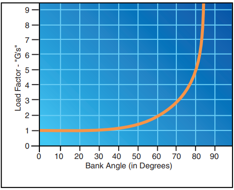
Figure 2-11. The load factor diagram allows you to calculate the amount of “G” loading exerted with various angle of bank.
Thrust
Thrust, like lift, is generated by the rotation of the main rotor system. In a helicopter, thrust can be for- ward, rearward, sideward, or vertical. The resultant of lift and thrust determines the direction of movement of the helicopter.
The solidity ratio is the ratio of the total rotor blade area, which is the combined area of all the main rotor blades, to the total rotor disc area. This ratio provides a means to measure the potential for a rotor system to provide thrust.
The tail rotor also produces thrust. The amount of thrust is variable through the use of the antitorque ped- als and is used to control the helicopter’s yaw.
Drag
The force that resists the movement of a helicopter through the air and is produced when lift is developed is called drag. Drag always acts parallel to the relative wind. Total drag is composed of three types of drag: profile, induced, and parasite.
PROFILE DRAG
Profile drag develops from the frictional resistance of the blades passing through the air. It does not change significantly with the airfoil’s angle of attack, but increases moderately when airspeed increases. Profile drag is composed of form drag and skin friction.
Form drag results from the turbulent wake caused by the separation of airflow from the surface of a structure. The amount of drag is related to both the size and shape of the structure that protrudes into the relative wind. [Figure 2-12]
Skin friction is caused by surface roughness. Even though the surface appears smooth, it may be quite rough when viewed under a microscope. A thin layer of air clings to the rough surface and creates small eddies that contribute to drag.
INDUCED DRAG
Induced drag is generated by the airflow circulation around the rotor blade as it creates lift. The high-pressure area beneath the blade joins the low-pressure air above the blade at the trailing edge and at the rotor tips. This causes a spiral, or vortex, which trails behind each blade whenever lift is being produced. These vortices deflect the airstream downward in the vicinity of the blade, creating an increase in downwash. Therefore, the blade operates in an average relative wind that is inclined downward and rearward near the blade. Because the lift produced by the blade is perpendicular
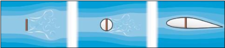
Figure 2-12. It is easy to visualize the creation of form drag by examining the airflow around a flat plate. Streamlining decreases form drag by reducing the airflow separation.
Aircraft Yaw—The movement of the helicopter about its vertical axis.
to the relative wind, the lift is inclined aft by the same amount. The component of lift that is acting in a rear- ward direction is induced drag. [Figure 2-13]
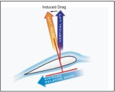
Figure 2-13. The formation of induced drag is associated with the downward deflection of the airstream near the rotor blade.
As the air pressure differential increases with an increase in angle of attack, stronger vortices form, and induced drag increases. Since the blade’s angle of attack is usually lower at higher airspeeds, and higher at low speeds, induced drag decreases as airspeed increases and increases as airspeed decreases. Induced drag is the major cause of drag at lower airspeeds.
PARASITE DRAG
Parasite drag is present any time the helicopter is moving through the air. This type of drag increases with airspeed. Nonlifting components of the helicopter, such as the cabin, rotor mast, tail, and landing gear, contribute to par- asite drag. Any loss of momentum by the airstream, due to such things as openings for engine cooling, creates additional parasite drag. Because of its rapid increase with increasing airspeed, parasite drag is the major cause of drag at higher airspeeds. Parasite drag varies with the square of the velocity. Doubling the airspeed increases the parasite drag four times.
TOTAL DRAG
Total drag for a helicopter is the sum of all three drag forces. [Figure 2-14] As airspeed increases, parasite drag increases, while induced drag decreases. Profile drag remains relatively constant throughout the speed range with some increase at higher airspeeds. Combining all drag forces results in a total drag curve. The low point on the total drag curve shows the air- speed at which drag is minimized. This is the point where the lift-to-drag ratio is greatest and is referred to as L/Dmax. At this speed, the total lift capacity of the helicopter, when compared to the total drag of the heli- copter, is most favorable. This is important in helicopter performance.
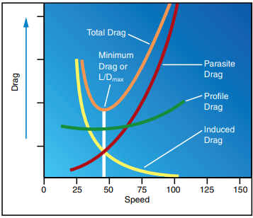
Figure 2-14. The total drag curve represents the combined forces of parasite, profile, and induced drag; and is plotted against airspeed.


