Aerodynamic Terms
Airfoil is the term used for surfaces on a powered parachute that produce lift, typically the wing itself.
Although many different airfoil designs exist, all airfoils produce lift in a similar manner.
Camber refers to the curvature of a wing when looking at a cross section. A wing possesses upper camber on its top surface and lower camber on its bottom surface. Leading edge describes the forward edge of the airfoil. The rear edge of the airfoil is called the trailing edge. The chord line is an imaginary straight line drawn from the leading edge to the trailing edge.
[Figure 2-1]
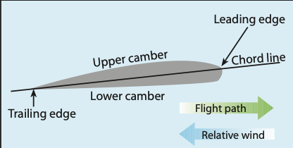
Figure 2-1. Aerodynamic terms of an airfoil.
Relative wind is the direction of the airflow with respect to the wing; it is usually parallel to and opposite the PPC flight path. Relative wind may be affected by movement of the PPC through the air, as well as by all forms of unstable, disturbed air such as wind shear, thermals, turbulence, and mountain rotors. When a PPC is flying through undisturbed air, the relative wind is parallel to and opposite the flight path.
Angle of attack is the angle between the relative wind and the wing chord line. [Figure 2-2]
Longitudinal axis is an imaginary line about which the aircraft rolls; it is also called the roll axis. The longitudinal axis is not a fixed line through the cart because the angle of incidence changes in turbulence and with loading changes.
Angle of incidence is the angle formed by the chord line of the wing and the longitudinal axis of the PPC cart. The cart longitudinal axis is not the same as the aerodynamic longitudinal axis defined in the previous paragraph. [Figure 2-2] Unlike an airplane, the angle of incidence can change in flight because of the flexible line attachment between the wing and the cart.
Angle of incidence can change for different types of flight configurations and PPC designs; this is covered in detail in the “Moments” section.
Trim angle is the angle between the chord line of the wing and the horizontal plane when the PPC is in non-powered gliding flight. [Figure 2-3] The PPC wing is designed at a slight angle, with the chord line inclined downward to the horizontal plane to maintain the manufacturer-designed angle of attack during gliding, level and climbing flight. This “trim angle” is built into the powered parachute by the manufacturer and cannot be adjusted by the pilot moving the controls.
Pitch angle is the angle the PPC wing chord makes with the horizontal plane. Pitch angle is what you can see. Many pilots confuse the pitch angle, which you can easily see and feel, with the angle of attack which may not be as perceptible. [Figure 2-4] For example, the pitch angle in an engine-out glide could be minus 8 degrees, in level flight 10 degrees above the hori-zon, and in a climb it could be 28 degrees above the horizon. These are significantly different angles you easily see. Pitch angles are covered in greater detail in Chapter 6.
Deck angle is the angle of the cart’s lower frame (from the front wheel to the rear wheels), to the landing surface. The deck on the lower part of the conventional cart frame can be used to visualize deck angle.
An imaginary line between the front and back wheel axles can also be used on unconventional carts.
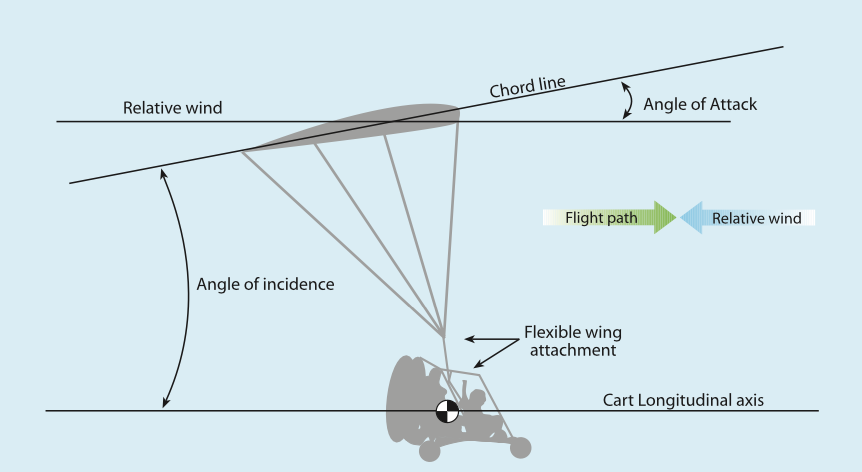
Figure 2-2. Angle of incidence.
Planform is the shape or form of a wing as viewed from above. The PPC wing comes in two wing plan- forms: rectangular, and elliptical. [Figure 2-5] The el- liptical planform leading and trailing edges are curved to form an elliptical shape when viewed from the top or bottom. These two shapes have unique flying char- acteristics. Rectangular wings typically produce more drag, are lower-performance, and do not move fore and aft, relative to the cart, as quickly as elliptical wings. These characteristics are more obvious when the wing is inflating, during pitch changes, and when flying in turbulence. Rectangular wings are therefore more stable and require less effort to fly. Elliptical wings are higher-performance and more efficient due to less drag. Elliptical wings react more quickly with changing conditions and require greater pilot experi- ence and skill during inflation, in turbulent air, and with abrupt throttle changes.Aspect ratio is the wingspan divided by the average chord line. A PPC with a common 500-square foot rectangular wing (about a 38-foot wingspan) and with a typical mean chord line of 13 feet, would have an average aspect ratio of about 3. This relatively low aspect ratio is less efficient at producing lift. An ellip- tical wing with the same 500 square feet and a 45-foot wing span and an 11-foot average chord would have an aspect ratio of about 4. The PPC wing is similar to airplane wings in that the aspect ratio will differ with the specific design mission for the aircraft. Generally,
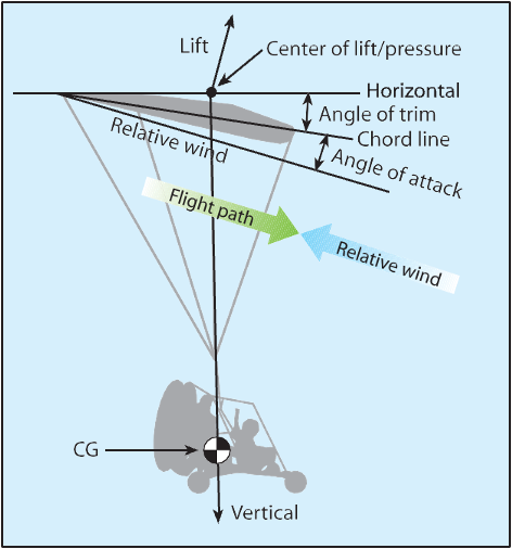
Figure 2-3. Angle of trim and center of pressure in gliding flight.
rectangular wings have lower aspect ratios and lower efficiency than the higher aspect ratio and higher effi- ciency elliptical wings. Generally, a high aspect ratio wing, compared to a low aspect ratio wing, produces higher lift at lower angles of attack with less induced drag. [Figure 2-6].
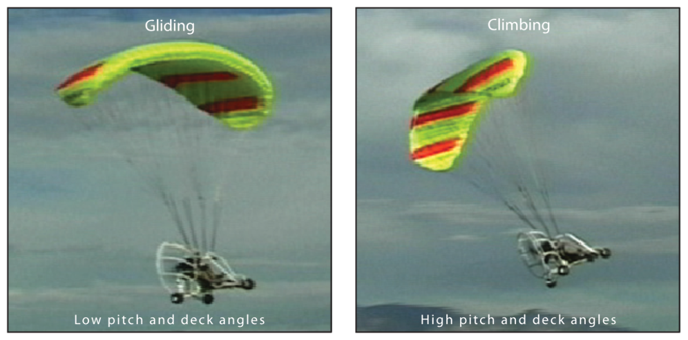
Figure 2-4. Gliding and climbing pitch angles.
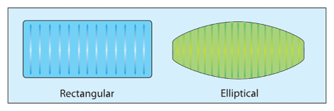
Figure 2-5. Planform view of a PPC inflated wing: rectangular and elliptical.
Wing loading is a term associated with the total weight the ram-air wing must support. Wing loading is found by dividing the total weight of the aircraft, in pounds, by the total area of the wing, in square feet. Wing loading is found by dividing the weight of the aircraft, in pounds, by the total area of the wing, in square feet. For example, the wing loading would be 2.0 pounds per square foot when 1,000 pounds—a common weight for a two-seat PPC with two people — is under a 500-square foot wing. If flying with one person the aircraft weight might be 700 pounds and the wing loading would decrease to 1.4 pounds per square foot.
Gliding flight is flying in a descent with the engine at idle or shut off.
Powered Parachute Wing Pressurization and Flexibility
The powered parachute has two distinctive modes: (1) inflated, it is a ram-air wing with a curved arc—a recognizable airfoil shape; and (2) deflated, it is a canopy that is either lying flat on the ground or packed into a bag.
Note: Chapter 7, Takeoffs and Departure Climbs, will detail the methods of getting the uninflated canopy laying on the ground turned into a flying wing. Since the aerodynamics of the PPC do not start until the wing is completely inflated, this chapter will assume each reference to the PPC wing is to an inflated ram-air wing already in the shape of an airfoil.
The powered parachute ram-air wing retains its air–
foil shape due to the air pressurizing the inside cells via the relative wind airflow being rammed into the front openings of the canopy—thus the term “ram-air wing.” The pressure inside the wing is much higher than the outside top and bottom because the dynamic pressure from the relative wind is converted to static sppreesesdu,re to pressurize the wing. The greater the the greater the pressure inside the wing and the more rigid the wing. The cell openings are designed to be perpendicular to the relative wind to achieve maximum pressure from the relative wind. This static in- internal pressure harnessed from the relative wind is called dynamic pressure (q) and is determined by the velocity squared times the air density factor. [Figure
2-7] Note the dynamic air pressure converted to static pressure at point A is constant throughout the wing points B and C. This static pressure is always greater than the pressure outside the wing at points X and Z.
Cross-port openings are placed in the ribs of each cell, connecting the adjoining cells. These cross-ports are dispersed throughout the wing (with exception to the outboard side of the end cells) to maintain positive pressure throughout. The pressure is constant inside
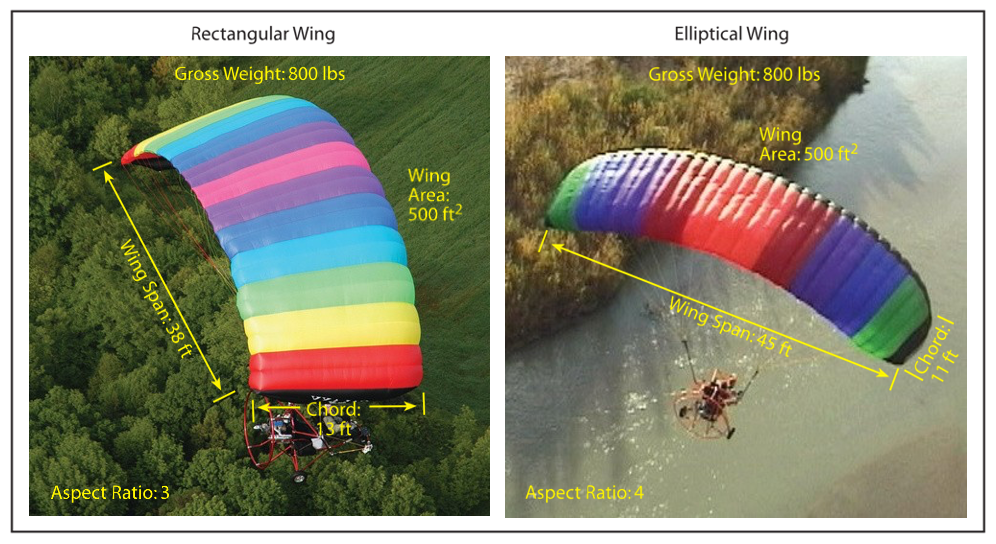
Figure 2-6. spect ratio comparisons for wings with similar areas.
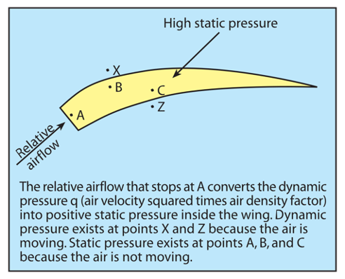
Figure 2-7. Dynamic pressure.
the wing because the dynamic pressure hitting the opening is the same for each cell and the speed is the same. The cross-ports aid the complete wing in becoming pressurized during inflation and maintain- ing the pressure throughout the wing in turbulence. [Figure 2-8]
The inflatable wing airfoil generally remains a consis-
tent shape as designed by the manufacturer. However, pilot control of the wing to make a turn significantly changes the relative aerodynamic qualities of the PPC wing by pulling down the trailing edge similar to a flap on an airplane. [Figure 2-9]
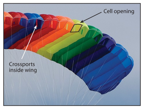
Figure 2-8. Cell openings and cross-port view.
Faster speeds from smaller wings or more weight cre- ate a higher pressure in the wing resulting in higher control forces because of the higher internal pressure.
Forces in Flight
Like all aircraft, the four forces that affect PPC flight are thrust, drag, lift, and weight. [Figure 2-10] In steady PPC flight:
- The sum of all upward forces equals the sum of all downward forces.
- The sum of all forward forces equals the sum of all backward forces.
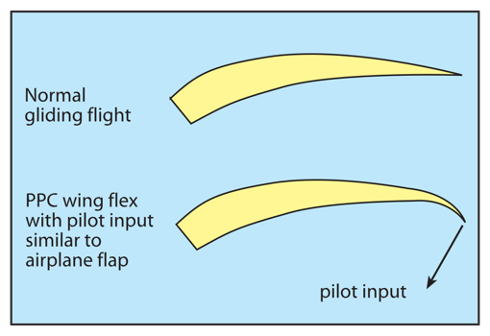
Figure 2-9. PPC wing flexibility in flight.
3. The sum of all moments equals zero.
THRUST – the forward force produced by a power-
plant/propeller as it forces a mass of air to the rear (usu- ally said to act parallel to the longitudinal axis).
VS
DRAG – the aerodynamic force acting on the airfoil lines and cart in the same plane and in the same direc- tion as the relative wind.
LIFT – the aerodynamic force caused by air flowing over the wing that is perpendicular to the relative wind.
VS
WEIGHT – the force of gravity acting upon a body.
Lift
Lift opposes the downward force of weight and is pro- duced by the dynamic effects of the surrounding air- stream acting on the wing. Lift acts perpendicular to the flight path through the wing’s center of lift. There is a mathematical relationship between lift, angle of attack, airspeed, altitude, and the size of the wing. In the lift equation, these factors correspond to the terms coefficient of lift, velocity, air density, and wing sur- face area. The relationship is expressed in Figure 2-11.
This shows that for lift to increase, one or more of the ifnacrteoarsse.on the other side of the equation must
Lift is proportional to the square of the velocity, or airspeed, therefore, doubling airspeed quadruples the amount of lift if everything else remains the same. Small changes in airspeed create larger changes in lift. Likewise, if other factors remain the same while the coefficient of lift increases, lift also will increase. The coefficient of lift goes up as the angle of attack is increased. As air density increases, lift increases. However, you will usually be more concerned with
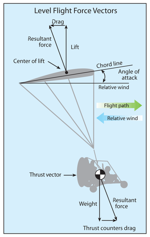
Figure 2-10. Level flight forces.
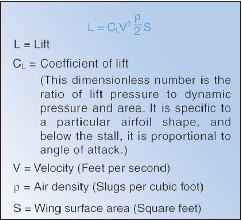
Figure 2-11. The lift equation.
how lift is diminished by reductions in air density on a hot day, or if you are operating at higher altitudes.
All wings produce lift in two ways:
- Airfoil shape creating a higher velocity over
the top of the wing and a lower velocity over the bottom of the wing with Bernoulli’s venturi effect.
- Downward deflection of airflow because of the curvature of the wing with the principle of
Newton’s Third Law of Motion: For every action,
there is an equal and opposite reaction.
Both principles determine the lifting force. Review
Chapter 2 in the Pilot’s Handbook of Aeronautical Knowledge to understand Newton’s laws of motion and force and Bernoulli’s principle of pressure.
Drag
Drag is the resistance to forward motion through the air. Drag opposes thrust. Aerodynamic drag comes in two forms:
- Induced drag: a result of the wing producing lift;
- Parasite drag: resistance to the airflow from
the cart, its occupants, suspension lines from the wing, interference drag from objects in the airstream, and skin friction drag of the wing.
Induced drag is the result of lift, and its amount var-
ies as discussed above for lift. Induced drag creates organized circular vortices off the wing tips that gener- ally track down and out from each wingtip. [Figure 2- 12] This is true for all aircraft that use wings including PPC, weight-shift control and fixed wing aircraft. The bigger and heavier the aircraft, the greater and more powerful the wingtip vortices will be. This organized swirling turbulence is an important factor to understand for flight safety. Refer to Section 7-3 of the Aeronau- tical Information Manual (AIM) or Chapter 12 of the Pilot’s Handbook of Aeronautical Knowledge (FAA-H- 8083-25) for additional discussion.
Parasite drag is caused by the friction of air moving over the structure. Just as with lift, parasite drag in- creases as the surface area of the aircraft increases and dramatically increases as airspeed increases,
at the square of the velocity. Therefore, doubling the airspeed will quadruple your parasite drag. [Figure 2-13]
The PPC has relatively slow speeds, but plenty of items (area) for the wind to strike including wing, lines, pilot, cart, engine, wheels, and tubes. Parasitic drag can be reduced by streamlining the items but since the PPC flies at relatively slow airspeeds, the
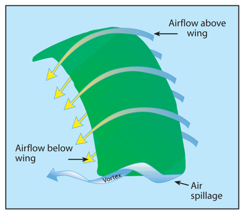
Figure 2-12. Turbulence — induced drag wingtip vortices — created by lift of the ram-air wing.
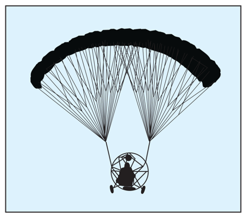
Figure 2-13. Frontal areas of the cart, wing, and occupants are the source of parasitic drag.
extra weight, cost, and complexity of streamlining the PPC is generally not incorporated into the design.
Total Drag is the combination of parasite and induced drag. Total Drag = Parasitic Drag + Induced Drag
To help explain the force of drag, the mathematical
equation D = Cd · q · S is used. In this equation drag
- is the product of drag coefficient (Cd), dynamic pressure (q) determined by the velocity squared times the air density factor, and surface area (S) of the cart and the ram-air wing (S). The drag coefficient is the ratio of drag pressure to dynamic pressure.
Induced and parasitic drag have opposite effects as angle of attack decreases and speed increases. Note the total drag. It is high at the slowest air speeds at high angles of attack near the stall, decreases to the lowest at the most efficient airspeed, and then pro- gressively increases as the speed increases. The PPC wing is typically designed to fly at a speed generally above lowest overall total drag. Too slow, and the wing would be near its critical angle of attack. Too fast, and the power to maintain level flight or climb would be excessive. The manufacturer determines the speed range of the wing based on the weight range, and the resultant location on the total drag diagram. [Figure 2-14]
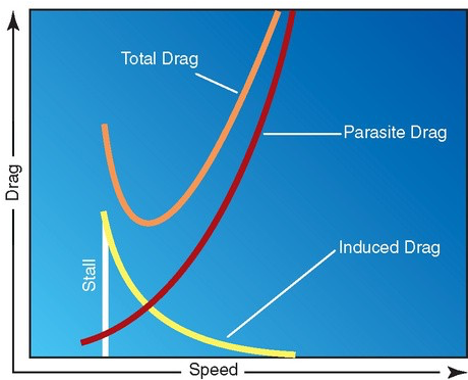
Figure 2-14. Relationship between drag and speed.
Weight
Weight is a measure of the force of gravity acting upon the mass of the PPC. It is the force that opposes lift, and acts vertically downward through the aircraft’s center of gravity. Weight consists of everything di- rectly associated with the powered parachute in flight: the combined load of the total PPC (wing, risers, en- gine, cart, fuel, oil, etc.), people (clothing, helmets, etc.), and baggage (charts, books, checklists, pencils, handheld GPS, spare clothes, suitcase, etc.). In stabi- lized level flight, when the vertical component of lift is equal to the weight force, the PPC is in a state of equilibrium and neither gains nor loses altitude.
Because the trim angle is set at the factory, the PPC
airspeed is predetermined, before takeoff, by the weight of the aircraft and the wing design. The more weight, the more forward airspeed is generated.
Therefore, gravity is the primary force for creating forward speed — pulling the wing through the rela- tive wind while airborne. The forces in gliding flight are very similar to those for an airplane or gliding sailplane. [Figure 2-15] Specific numbers presented in this chapter are examples to serve as a basis to understand the concepts. Each PPC has unique fly- ing characteristics and these numbers will be differ- ent, but can be compared to your PPC to provide a greater understanding of your unique performance. Note the component of weight acting along the flight path. This component of weight is called thrust by some but is more accurately the weight component providing the forward force.
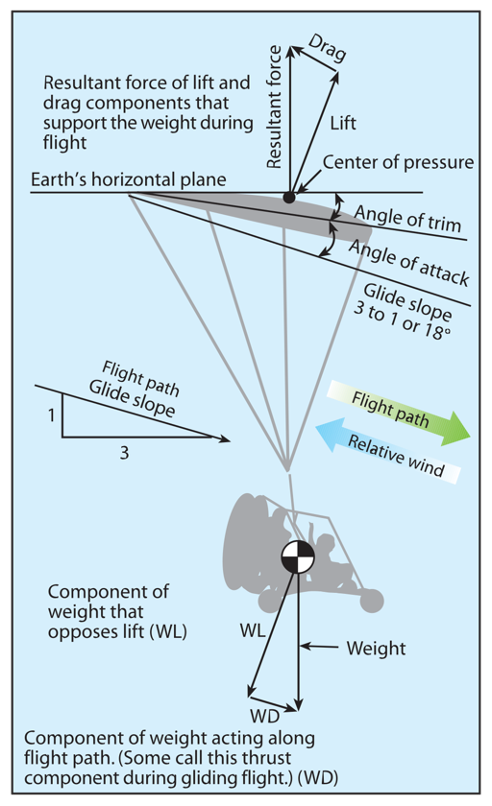
Figure 2-15. Typical forces in gliding flight, with no engine thrust.
Thrust
Compared to an airplane, as discussed in Chapter 3 of the Pilot’s Handbook of Aeronautical Knowledge, thrust serves different purposes in the PPC: (1) it is used to accelerate the PPC to flying speed while in- flating the wing (2) it is used to climb when at high thrust, cruise level at medium thrust, and descend at lower thrust. Variations in thrust have negligible effect
on PPC airspeed which remains relatively constant whether climbing, descending, or in level flight.
When enough thrust is added to produce level flight, the relative wind stream becomes horizontal with
the earth; the angle of attack and speed remain about the same. Just as described in the Pilot’s Handbook
of Aeronautical Knowledge for the airplane, thrust equals total drag for level flight. [Figure 2-16]
When in straight-and-level unaccelerated flight:
LIFT (L) = WEIGHT (W)
and
THRUST = TOTAL DRAG (DT)
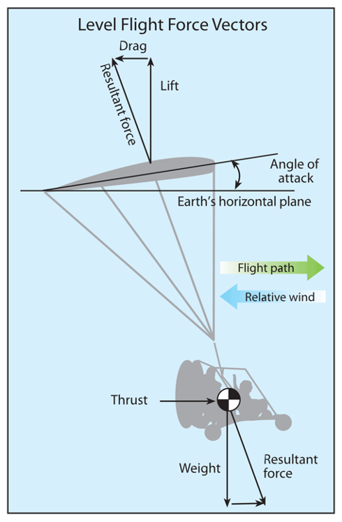
Figure 2-16. Powered parachute in level flight.
When excess thrust is added to produce climbing flight, the relative air stream becomes an inclined plane leading upward, while angle of attack and speed remain about the same. Just as described in the Pilot’s Handbook of Aeronautical Knowledge for the air- plane, the excess thrust determines the climb rate and climb angle of the flight path. [Figure 2-17]
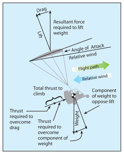
Figure 2-17. Powered parachute in climbing flight.
Center of Gravity
The center of gravity (CG) is the theoretical point of concentrated weight of the aircraft. It is the point within the PPC about which all the moments trying to rotate it are balanced. The most obvious difference in the center of gravity for a PPC is the vertical position compared to an airplane, as it is much lower than the wing. The Pilot’s Handbook of Aeronautical Knowl- edge accurately states the center of gravity is gener- ally in the vertical center of the fuselage. The same is true for the PPC. However, the PPC wing is high above the fuselage (cart) creating the unique pendu- lum effect flying characteristics of the PPC (which will be covered in detail later).
In a two-seat PPC, the second seat is typically behind
the pilot’s seat, and the center of gravity is usually located directly over the rear passenger seat. There- fore, the center of gravity location does not change significantly with or without a passenger. Fuel tanks are typically located near the center of gravity so
any differences in fuel quantity will not significantly change the center of gravity fore and aft with different fuel quantities.
Axes of Rotation
Motion about the lateral axis or pitch is primarily controlled by the thrust of the propeller moving the PPC pitch up (nose up) to climb and pitch down (nose down) at the reduced throttle.
Turning happens about the longitudinal axis and is the
result of the rolling motion similar to an airplane with aileron and rudder control. To turn, pull down the wing trailing edge on the side you want to turn to with the steering controls. This creates drag on the correspond- ing trailing edge of the wing, thus dropping the inside wing, and rolling the PPC into a banked turn. [Figure
2-18]
There is not significant turning about the vertical axis
because the PPC wing is designed to fly directly into the relative wind just like an airplane. Any sideways skidding or yaw is automatically corrected to fly straight with the wing design. An airplane uses the vertical tail to fly directly into the relative wind like a dart. The unique design of the PPC performs the same function through the combination of wing profile/ taper, the arch or curvature from tip to tip, washout built into the wing and/or tip stabilizer design. These factors make the PPC track directly into the relative wind and eliminate the need for a vertical tail surface and rudder to make coordinated turns. Designs and methods vary with manufacturer and wing type, but all PPCs are designed to track directly into the relative wind.
Ground Effect
Ground effect is the interference of the ground with the airflow and turbulence patterns created by the wing. The most apparent indication from ground effects is the unexpected lift given to an aircraft as it flies close to the ground — normally during takeoffs and landings.
Ground effect is usually felt when the wing is at altitudes of less than half of the wingspan. The typical PPC wingspan is approximately 38 feet with an average wing height of about 20 feet. Therefore, the ground effect is negligible for PPCs and is typically not a factor.
Moments
A body that rotates freely will turn about its center of gravity. In aerodynamic terms for a PPC, the mathematical value of a moment is the product of the force times the distance from the CG (moment arm) at which the force is applied.
Wings generally want to pitch nose down or roll for-
ward and follow the curvature of the airfoil creating a negative pitching moment. This is one of the reasons airplanes have tails. The powered parachute does not need a tail because the airfoil is locked into a specific position relative to the cart by the suspension lines. [Figure 2-19]. Any pitching moment for the wing is counteracted by the strong pendulum effect (weight of the cart hanging directly under the center of lift).
Any swinging of the weight creates moments that act to stabilize the swing. The wing aids to dampen swinging. This pendulum effect is unique to the PPC
because the cart has the ability to rotate around the PPC pendulum axis of rotation in addition to rotating about the CG.
To understand the pendulum effect, attach a small weight (a pencil or paper clip works) to a 24-inch string. Note the weight always wants to hang directly under where you hold it. If you hold the string still and move the weight to the side, the weight swings and stabilizes under where you hold it. Gravity, pulling down on the weight to stabilize it directly un- der where it is hanging, is PPC pendulum stability. [Figure 2-20]
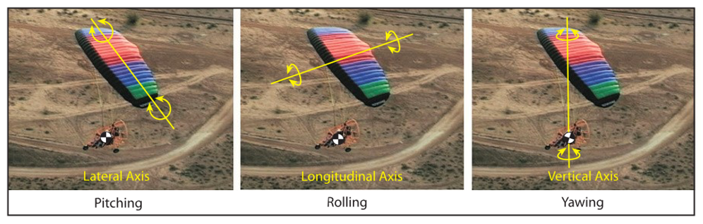
Figure 2-18. PPC axes of rotation.
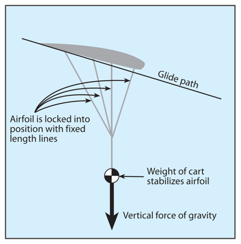
Figure 2-19. Powered parachute airfoil is locked into position by the lines and weight of the cart.
Pendulum stability is the result of a number of PPC design characteristics: there is no downward force from a horizontal tail that must be counteracted by the wing producing more lift; there is no weight of the tail that must be lifted; and there is no tail to impose extra drag on the aircraft. Gravity is the primary force that stabilizes the aircraft using pendulum stability.
The “dynamic pendulum effect” can be demonstrated
by swinging the weight around and then stopping the swinging to notice that the weight keeps swinging from the momentum. The swinging weight is known as the “dynamic pendulum effect” which will be dis- cussed in detail later.
Thrust Line Moments
PPC designs can have different moments caused by thrust; the propeller thrust may be above the CG (Figure 2-21 left) or go through the CG (Figure 2-21 right). Since the cart swings free in pitch, this CG thrust moment can slightly affect the pitch of the cart in relation to the wing.
PPCs with an attachment point above the thrust line
have a pitching nose up moment as shown in Figure 2-21 (both diagrams), with a thrust line, wing attach point, and arm “b.”
Gravity Moment
There is a moment arm from the CG of the cart, to the cart/wing attachment (see “arms” in Figure 2-22). The longer the distance from the CG to the

Figure 2-20. The pendulum effect is like a weight on a string, stabilizing weight and line vertically over time.
wing attachment point, the more stable the cart pitch is from thrust moments. The higher the wing attachment point above the CG, the more stable the cart is from swinging underneath and the less the cart will pitch up when thrust is applied.
A higher hang point will also better stabilize the PPC
cart in turbulence because the moment of the weight and the larger “d” arm create a larger stabilizing movement. [Figure 2-22]
For ground operations, the moment arm distance “c”
cannot be too great or the front wheel would lift off the ground prematurely, trying to inflate the wing (see right side of Figure 2-22).
During the flight, the advantage of a high attachment
point arm “c” is less swinging around of the cart under the wing, and less cart “pitch up” when the throttle is applied to climb. This high attachment point creates thrust that is now pointed slightly down to the relative wind, which has two significant effects. First, it creates a negative P-factor, counteracting increased torque. The second effect is a disadvantage: less climb rate or more thrust required for the same climb rate. This is due to the increased load on the wing from the thrust, requiring more speed and/or angle of attack to lift the total load. [Figure 2-23]
Wing Attachment to Cart
If flying straight and level over a perfectly flat landing strip, then with the rear wheels 1 inch above the run-
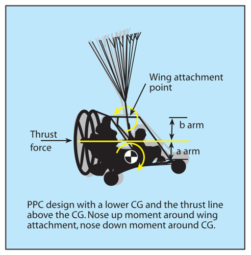
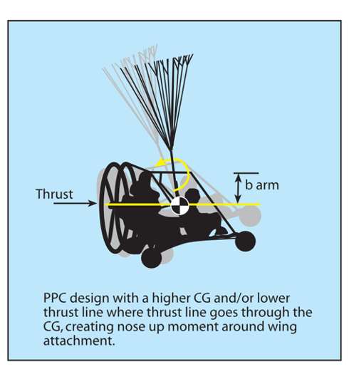
Figure 2-21. PPC designs can have different moments caused by thrust; the propeller thrust may be above the CG (left) or go through the CG (right). A PPC can have wing attachment thrust moments as shown, or no wing attachment thrust moment if the thrust line goes through the wing attachment point (not shown).
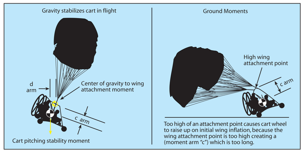
Figure 2-22. Gravity stabilizes thrust moment.
way, the nose wheel should be between 7 and 11 inches above the pavement. The POH specifies the wing fore and aft wing attachment points to the cart. [Fig- ure 2-24] Attaching the wing too far forward would cause the nose wheel to be higher than it should be. – Attaching the wing too far back would place the nose wheel too low, where it would hit first for landings. Balancing the cart properly per the POH is important to make sure the cart is hanging properly under the wing and ensure the thrust is properly aligned as designed by the manufacturer. Nose wheel low means thrust pointing down, increasing loads, and airspeed. The nose wheel high has the opposite effect. Thrust aligned too high or too low results in reduced thrust and unwanted P-factor.
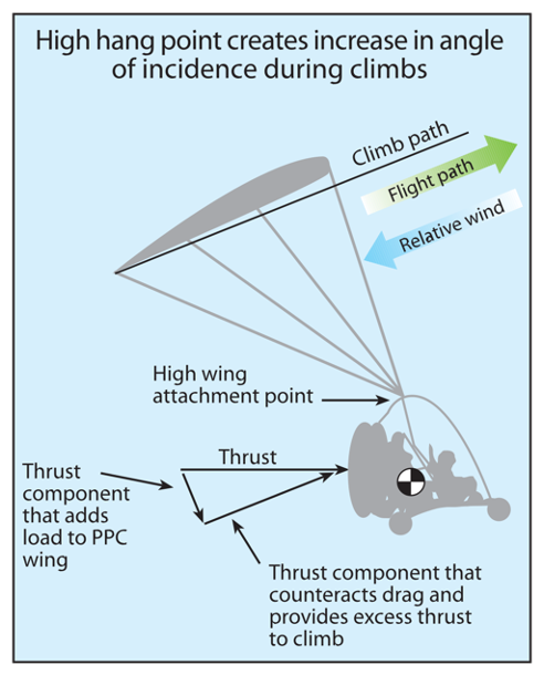
Figure 2-23. High wing attachment point effects in flight.
Manufacturers must balance the cart stability for take- off and flight, along with the thrust moment to achieve the best design for the specific application.
Stability
A stable aircraft is one that will routinely return to its original attitude after it has been disturbed from this condition; usually, this means returning to straight-and-level flight after encountering turbulence that disrupts a normal flightpath. The more stable the aircraft, the easier it is to return to a straight and level position. The natural tendency of the pendulum — the PPC cart hanging under the wing — is to return to its original centered position under the wing. The pendulum design gives the PPC airborne positive dynamic stability and positive static stability for roll and pitch because the weight of the pendulum wants to return the PPC to level stabilized flight. No matter what maneuver within the POH limitations the PPC is put through (regardless of whether it is pilot-induced or turbulence-created), as soon as the disruptive force stops, the aircraft is designed to return to a stabilized flight condition, with virtually no pilot input. Figure 2-25 shows the movements of the PPC as it auto-corrects from a side gust of wind.
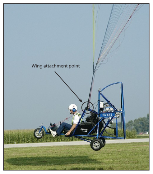
Figure 2-24. Straight and level flight with the nose wheel 7 to 11 inches above the horizontal flight path.
PPC Angle of Attack Characteristics
Normal Flying Conditions
For all practical purposes, the wing’s lift in a steady state normal climb is the same as it is in a steady level flight at the same airspeed. Though the flightpath has changed when the climb has been established, the angle of attack of the wing with respect to the inclined flightpath reverts to practically the same value, as does the lift. The angle of attack remains relatively constant for constant weights during stabilized flight for glide, level cruise or climb. However, wind gusts, flying in turbulence, quick uncoordinated flight (as covered later), or aerobatic maneuvers can change the PPC angle of attack. PPC limitations in the POH are specifically written to avoid any maneuver that would temporarily get the PPC into a situation of too high or too low an angle of attack. The PPC is specifically designed to fly at an angle of attack to avoid stalls (resulting from too high an angle of attack) and avoid wing collapses (resulting from too low an angle of attack). Each manufacturer specifically determines the limitations so a proper angle of attack is maintained throughout the flight operation range.
The basic design of the powered parachute is to fly at a relatively constant speed which results in a constant angle of attack. However, the angle of attack can change just as with any aircraft as when a gust of wind
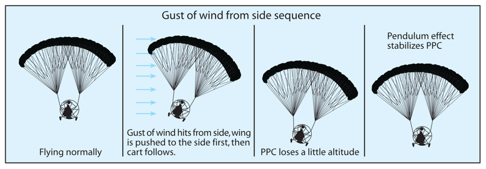
Figure 2-25. PPC stability after a side wind gust.
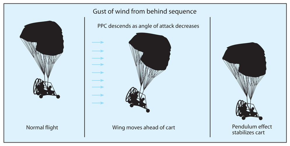
Figure 2-26. AOA changes as wind hits the airfoil.
changes the direction the air is hitting the airfoil. [Fig- ure 2-26]
The pilot can add weight or increase loads which may also increase the angle of attack slightly.
Flaring Increases Angle of Attack
The flare (pulling down the trailing edges of the wing— and thus lowering the trailing edge) increases the angle of attack. [Figure 2-27] In a flare, the trail- ing edges of the wing are pulled down (usually, as both foot steering controls are pushed forward). This is similar to lowering the flaps on an airplane: lift is increased, drag is increased, and for a PPC, the angle of attack is increased. The result is that the higher drag wing slows down and thus the wing moves backward relative to the cart. So as the total weight of the pendulum (the cart and occupants) moves forward of the wing, the angle of attack increases, generating more lift and more drag. The pendulum is the weight of the CG under the wing which swings forward for this transient situation due to pendulum effect.
Note that flare provides a temporary large increase in
the angle of attack (AOA) until the pendulum swings back underneath the wing. This action thus returns the wing to the normal stable flight configuration — the cart (the total weight of the pendulum) under the center of the wing. Therefore, a flare will only temporari- ly add an increase to lift and drag. Once the pendulum swings back down, the drag of the wing, and therefore the reduced airspeed, will continue until the flare is released.
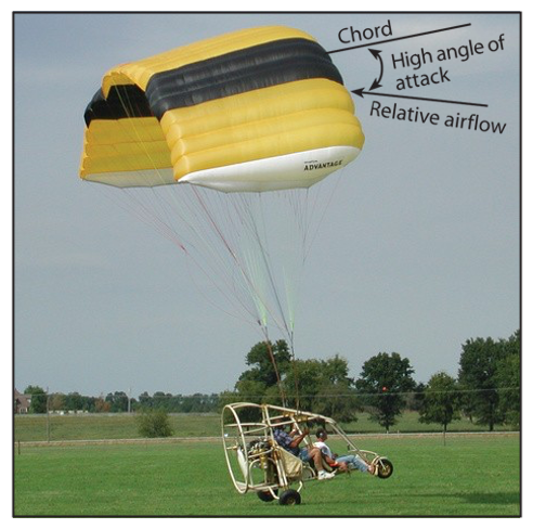
Figure 2-27. Flare on landing typically increases the angle of attack
Porpoising Creates Variations in AOA
Another slight variation in the angle of attack is the swinging pendulum action of the PPC when high-thrust engines provide a strong and immediate full thrust of the propeller. This extra thrust swings the cart through the pendulum arc relative to its position under the wing. This is why many times you will see the PPC take off and porpoise until it stabilizes. This is a good example of the dynamic pendulum effect. As the propeller thrust swings the cart out front, the cart peaks then swings back to center. The cart suc- cessively swings back and forth, continuing to reduce oscillations until it stabilizes in a climb. This porpois- ing is most common with a high power engine. This can be eliminated by using gradual throttle increases so as not to create a dynamic pendulum effect entering a climb.
Stalls: Exceeding the Critical Angle of Attack
The critical angle of attack is the angle of attack at which a wing stalls regardless of airspeed, flight altitude, or weight. The drawings in Figure 2-28 show airflow over a typical rectangular PPC wing. The first shows a laminar, smooth, lift-generating airflow— one that is typical when the angle of attack is within the flight range. The second depicts an exceeded angle of attack, turbulence, and loss of the lifting force. [Figure 2-28]
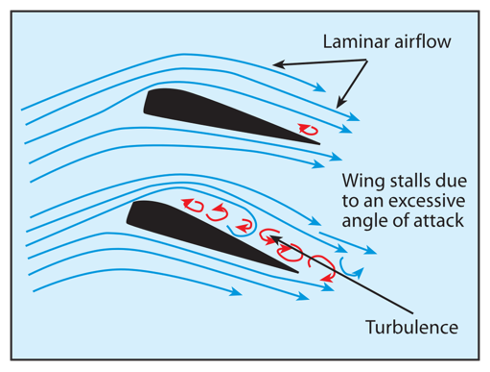
Figure 2-28. Wings stall due to an excessive angle of attack.
Unlike a fixed-wing aircraft that takes constant aware- ness of angle of attack to prevent a stall, the powered parachute wing is designed by the manufacturers to maintain a specified range of angle of attack and air- speeds. It is resistant to stalls because for all practical purposes, it is designed to fly at a constant normal operating range. This range is maintained if the operator flies within the operating limitations specified in the POH. Flying the PPC within the limitations specified
in the POH and avoiding turbulence means you will not exceed the critical angle of attack and stall the wing.
However, situations that could contribute to a stall are:
- A large increase in wing drag (full-flare)
— which the PPC pilot controls by pulling the wing back, thus increasing the AOA. (Note: A full-flare is normally used and recommended only for landings.)
- A quick full RPM throttle input, creates a climbing dynamic pendulum effect loading the wing.
- A quick reduction of throttle during a high pitch angle climb. This quickly turns a high pitch climb into a high angle of attack. The wing is initially pitched high, climbing the inclined plane under full power, then quickly changes to a gliding flight path when the throttle is reduced, just like an airplane.
- A wind gust from flying in turbulent air.
To prevent a stall, do not go to full-throttle while holding a full-flare, or as specified in the POH. Note: For an explanation of a stall recovery, see Chapter 12: Night, Abnormal, and Emergency Procedures.
Turning Effect
Torque is a reaction to the mass of the turning propel- ler. If the propeller is turning to the right, the reaction is for the cart to want to turn to the left. Therefore, a right turn is sometimes designed into the PPC system to counteract the torque.
PPC manufacturers compensate for this with various designs:
- Dual (counter-spinning) propellers. This is an
ideal way to counter prop torque, but counter- rotating gearboxes are complicated, more expensive, and weigh more.
- Different riser lengths. On a clockwise-turning propeller, the left riser is longer than the right.
- Swivel the wing attachment on a tilt bar above the cart.
- Adjust the PPC frame (longer on the left, shorter on the right) to compensate for the engine torque (for a clockwise spinning prop).
Additionally, P-factor, as discussed in the Pilot’s
Handbook of Aeronautical Knowledge can be a factor, producing a left turn if the nose of the cart is too high
through improper CG balance of the PPC. Rotating propeller gyroscopic action can also produce turning tendencies if a force is applied which would deflect the propeller from its existing plane of rotation.
There is no corkscrew effect of the slipstream on a PPC because it does not have a tail in the propeller prop blast.
Weight, Load, and Speed Changes
Greater load factor creates increases in speed. For un-accelerated and stabilized flight there are only slight variations in speed for different flight conditions. [Figure 2-29] For an 800-pound PPC in gliding flight, both the lift and drag components support the weight of the PPC (lift is 759 pounds, and drag is 252 pounds, with the resultant 800 pounds vertical force).
In level flight, the PPC does not have the vertical
component of total drag to support the weight so additional lift must be generated through speed or angle of attack increases.
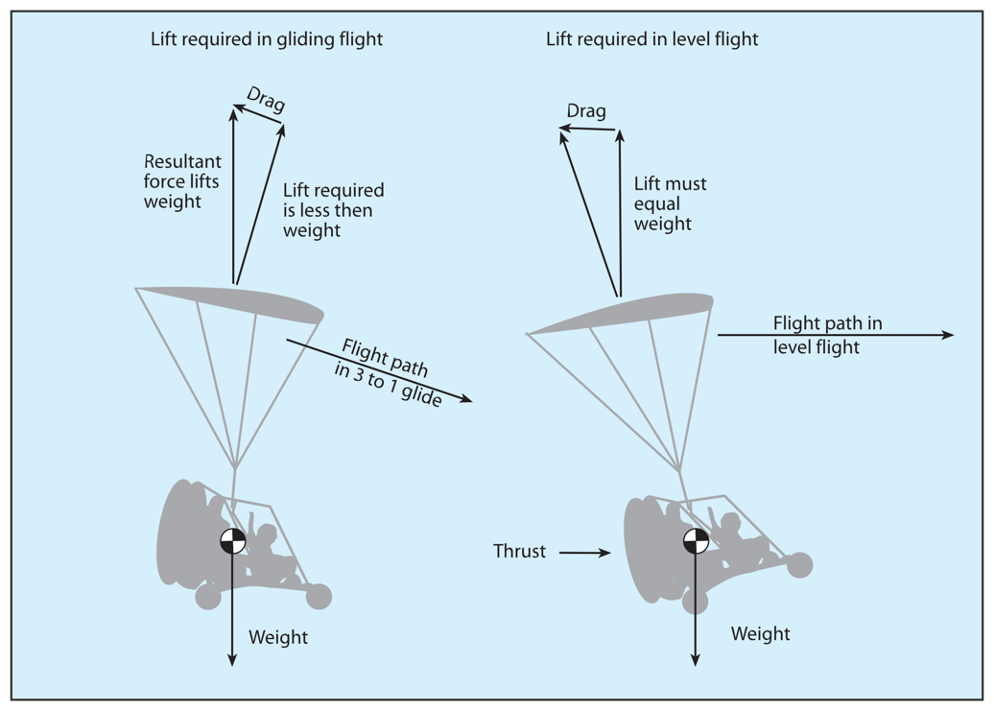
Figure 2-29. Forces differ between gliding and level flight.
The numbers are small and difficult to measure or feel so the industry rule of thumb is to assume the PPC flies at a constant speed and angle of attack with changes in throttle. However, increased load (weight) and load factor has a significant effect on speed. [Fig- ure 2-30]
As discussed in Chapter 2 of the Pilot’s Handbook of
Aeronautical Knowledge the following points apply to powered parachute operations:
- During straight and level flight, the lift opposes the weight.
- In a banked turn, the lift is no longer directly opposite the weight; it is losing some of the vertical components of lift. More lift is needed so the vertical component of lift will equal the weight.
- In a banked turn, lift must be increased and load factor goes up. [Figure 2-30]
In a 45-degree turn, the 800 pounds weight would equal 800 times 1.4 or 1,120 pounds total load. This 45-degree turn, 1.4 G loading is the same as adding 320 pounds of weight to the 800 pounds. This new 1,120 pounds of lift must be produced by the wing by increased speed and/or angle of attack. If all the additional lift is produced from airspeed, airspeed would increase about 5 MPH, a noticeable difference. Refer to your Pilot’s Operating Handbook to understand the specific design considerations for the aircraft you will be flying.
PPC Aerodynamics Summary
The following summarizes PPC aerodynamics:
- Increasing the throttle causes the PPC to climb, and decreasing the throttle allows the PPC to descend.
- The PPC flies at a relatively constant airspeed and angle of attack in normal flying conditions.
- The weight of the PPC controls steady-state airspeed under similar conditions of wing size and type, trim, steering line settings, and pilot flare. Increased weight or load factor increases speed and/or angle of attack.
- The lighter the weight, the slower the airspeed, the less control pressure on the wing, and the slower your descent.
- The heavier the cart (total weight under the wing), the faster the airspeed, the more effort required for maneuvers (foot steering pressure), and the faster your descent.
- The wing set (rectangular or elliptical), size, and cart weight have a strong influence on PPC performance and maneuverability.
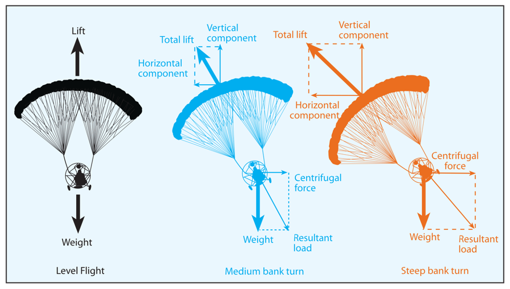
Figure 2-30. Loads and turning forces.


