This chapter covers the engines found on most powered parachutes and includes the exhaust, ignition, fuel, lubrication, cooling, propeller, gearbox, induction, charging, and fuel systems. Reciprocating engine operating theory is covered, for both two-stroke and four-stroke engines.
The powered parachute engine and propeller, often referred to as a powerplant, work in combination to produce thrust. The powerplant propels the powered parachute and charges the electrical system that supports PPC operation.
The engine is one of the key components of a powered parachute and should be maintained according to both the engine and airframe manufacturer recommendations. Preflight information, along with maintenance schedules and procedures, can be found in the Pilot’s Operating Handbook (POH) and/or maintenance references from the manufacturers.
Engine inspections and maintenance must be performed and documented in a logbook. You should review this logbook before flying an unfamiliar powered parachute.
Reciprocating Engines
Most powered parachutes are designed with reciprocating engines. Two common means of classifying reciprocating engines are:
- By the number of piston strokes needed to complete a cycle: two-stroke or four-stroke; and
- By the method of cooling: liquid or air-cooled.
Refer to Chapter 5 of the Pilot’s Handbook of Aeronautical Knowledge for a comprehensive review of how reciprocating four-stroke engines operate.
Two-Stroke Engines
Two-stroke engines are commonly used in powered parachutes. Two-stroke aviation engines evolved from two-stroke snowmobile and watercraft engines, the difference being that an aircraft engine is optimized for reliability with dual ignition often installed for each cylinder. Two-stroke engines are popular be- cause they have fewer components than four-stroke engines which makes them less expensive to manufacture, and lighter, thus increasing their power-to-weight ratio.
Two-stroke engines require that oil be mixed into the fuel to lubricate the engine, instead of being held in a sump and having a separate recirculating system like a four-stroke engine. Details on two-stroke oil mixing are covered later under the “Lubrication” section.
One stroke as the piston moves up is intake and compression, and the second stroke as the piston moves down is power and exhaust. The two-stroke engine performs the same functions as a four-stroke engine in half the strokes.
A wide range of valve systems are found on two-cycle engines, for the purpose of opening and closing ports in the cylinder to let fuel in and exhaust out at the proper time, similar to the intake and exhaust valves on a four-stroke engine. One-way pressure valves, called spring, reed, or poppet valves, open when the pressure drops within the crankcase, pulling the fuel from the carburetor into the crankcase. [Figure 4-1]
Mechanical rotary valves are driven off the engine, rotate to provide an opening at the precise time, and can be on the intake and exhaust ports. [Figure 4-2]
Piston porting does not use any valves. The fuel inlet port is opened and closed by the piston position as it moves up and down in the cylinder. This is called a “piston ported inlet” and will be used in the Two-Stroke Process description that follows. [Figure 4-3]
The two-stroke process begins with the fuel entering the engine and concludes as it exits as exhaust. [Figure 4-3]
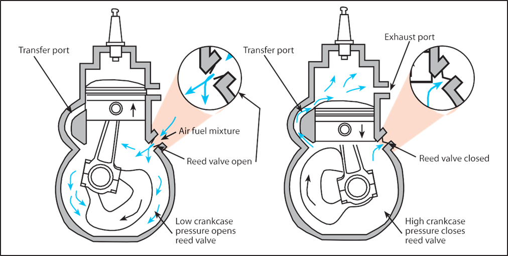
Figure 4-1. The Reed valve is open with low pressure and closes when the pressure increases.
Crankcase Vacuum Intake Stroke—Piston Moving up: Figure 4-3 a to b
The upward stroke of the piston [Figure 4-3a] creates a vacuum in the crankcase and pulls the fuel/ air/oil mixture into the crankcase through the intake valve system from the carburetor. [Figure 4-3b] This can be a pressure-actuated reed valve, a rotary valve, or a third ported inlet system where the lower piston skirt provides an opening for the fuel/air/oil mixture to flow in when the piston is reaching its highest point Top Dead Center (TDC). At this point, the greatest portion of the fuel/air/oil mixture has filled the crankcase.
Crankcase Compression Stroke—Piston Moving down: Figure 4-3 b to c
During the downward stroke, the pressure valve is forced closed by the increased crankcase pressure, the mechanical rotary valve closes, or the piston closes off the fuel/air oil mixture intake port. The fuel mixture is then compressed in the crankcase during the downward stroke of the piston.
Crankcase Transfer/Exhaust—Piston at lowest: Figure 4-3 d
When the piston is near the bottom of its stroke, the transfer port opening from the crankcase to the combustion chamber is exposed, and the high-pressure fuel/air mixture in the crankcase transfers around the piston into the main cylinder.
This fresh fuel/air/oil mixture pushes out the exhaust (called scavenging) as the piston is at its lowest point and the exhaust port is open. Some of the fresh fuel/ air/oil mixtures can escape out the exhaust port resulting in the higher fuel use of the two-stroke engine.
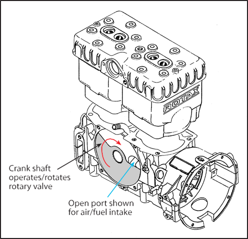
Figure 4-2. Intake rotary valve for a two-cycle engine.
Cylinder start of Compression Stroke—Piston initially Moving up: Figure 4-3 e
As the piston starts to move up, covering the transfer port, the tuned exhaust bounces a pressure wave at the precise time across the exhaust port (more on this in the exhaust system discussion) to minimize the fuel/air/oil mixture from escaping out the ex- host port.
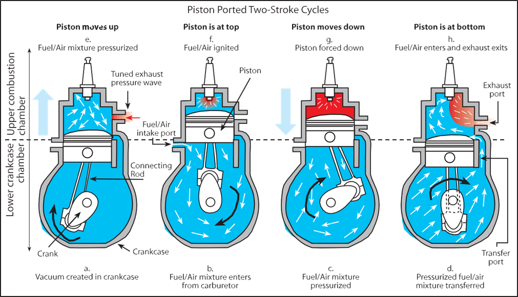
Figure 4-3. Piston ported inlet for a two-cycle engine.
Cylinder Compression Stroke—Piston Moving Up: Figure 4-3 e to f
The piston then rises, and compresses the fuel mixture in the combustion chamber. During this piston compression process, the crankcase vacuum intake process is happening simultaneously, as described earlier. This is why four processes can happen in two strokes.
Cylinder Power Stroke—Piston Moving Down:
Figure 4-3 f to g
At the top of the stroke, the spark plug ignites the fuel mixture and drives the piston down as the power stroke of the engine.
Cylinder Power Stroke—Piston Moving Down:
Figure 4-3 g to h
As the piston passes the exhaust port, the exhaust starts to exit the combustion chamber. As the piston continues down, the transfer port opens and the swirling motion of the air/fuel/oil mixture pushes the exhaust out the exhaust port.
Piston Reverses Direction From Down Stroke to Up Stroke: Figure 4-3 h to a
As the piston reverses direction from the down stroke to the up stroke the process is complete.
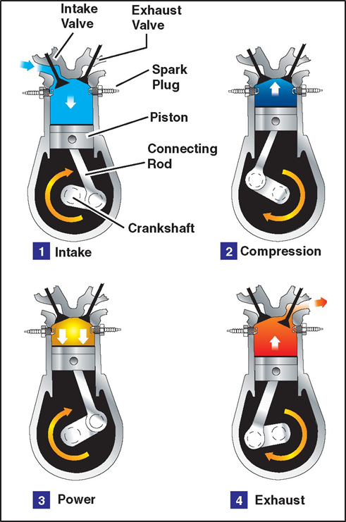
Figure 4-4. The cycles in a four-stroke engine.
Four-Stroke Engines
Four-stroke engines are very common in most aircraft categories and are becoming more common in powered parachutes. [Figure 4-4] Four-stroke engines have a number of advantages, including reliability, fuel economy, longer engine life, and higher horsepower ranges.
These advantages are countered by a higher acquisition cost, lower power-to-weight ratios, and a higher overall weight. The increased weight and cost are the result of additional components, e.g., camshaft, valves, complex head to house the valve train, etc., incorporated in a four-stroke engine.
Exhaust Systems
Engine exhaust systems vent the burned combustion gases overboard, reduce engine noise, and (in the case of two-stroke engines) help keep the fresh fuel-air mixture in the cylinders. An exhaust system has exhaust piping attached to the cylinders, as well as a muffler. The exhaust gases are pushed out of the cylinder and through the exhaust pipe system to the atmosphere.
Some exhaust systems have an exhaust gas temperature probe. This probe transmits an electric signal to an instrument in front of the pilot. This instrument reads the signal and provides the exhaust gas temperature (EGT) of the gases at the exhaust manifold. This temperature varies with power and with the mixture (ratio of fuel to air entering the cylinders), and is used to make sure the fuel-air mixture is within specifications. When there is a problem with carburetion, the EGT gauge will normally be the first notification for a pilot.
Two-Stroke Tuned Exhaust Systems
In two-stroke engines, the exhaust system increases the fuel economy and power of the engine. The two-stroke exhaust system is an integral part of any two-stroke engine design; often controlling peak power output, the torque curve, and even the RPM limit of the engine.
The exhaust system must be tuned to produce a back pressure wave to act as an exhaust valve. When hot spent gases are vented out of the exhaust port, they are moving fast enough to set up a high-pressure wave. The momentum of that wave down the exhaust pipe diffuser lowers the pressure behind it. That low pressure is used to help suck out all of the residual, hot, burnt gas from the power stroke and at the same time help pull a fresh fuel-air charge into the cylinder. This is called scavenging and is an important function of a tuned two-stroke exhaust system.
The design of the exhaust converging section causes a returning pressure wave to push the fresh fuel-air charge back into the exhaust port before the cylinder closes off that port. That is called pulse-charging and is another important function of the exhaust system.
Tuned exhaust systems are typically tuned to a particular RPM range. The more a certain RPM range is emphasized, the less effective the engine will operate at other RPMs. Vehicles like motorcycles take advantage of this with the use of transmissions. Mo- motorcycle exhaust pipe builders can optimize a certain RPM range and then the driver shifts gears to stay in that range. Aircraft, with no transmission, do not have this ability.
On an aircraft, an exhaust pipe has to be designed to operate over a broad range of RPMs from idle to full speed. This is part of the reason that simply putting a snowmobile engine on a powered parachute doesn’t work well.
Overall, the two-stroke exhaust system for a PPC is a specific design and must be matched to the engine to operate properly and obtain the rated power. It also reduces noise and directs the exhaust to an appropriate location. Exhaust silencers can be added to reduce noise but additional weight, cost, and slight power reduction are the byproducts.
Four-Stroke Engine Exhaust Systems
Four-stroke engines are not as sensitive as two-stroke engines because they have exhaust valves and therefore do not need the precision pulse-tuned exhaust system. However, directing the exhaust out appropriately and reducing the noise are important considerations. Again, using the manufacturer’s recommended configurations is required for Special Light Sport Aircraft (S-LSA) and recommended for Experimental Light Sport Aircraft (E-LSA).
Two-Stroke Engine Warming
Two-stroke engines must be warmed up because metals expand at different rates as they heat up. If you heat up steel and aluminum, you will find that the aluminum parts expand faster than the steel parts. This becomes a problem in two different areas of many two-stroke engines. The first place is in the cylinders of the engine.
The cylinders have steel cylinder walls that expand slowly compared to aluminum pistons that expand quickly. If an engine is revved too quickly during takeoff before warming up, a lot of heat is generated on top of the piston. That quickly expands the piston, which can then seize in the cylinder. A piston seizure will stop the engine abruptly.
The second area of concern is lower in the engine around the engine crankshaft. This is an area where things may get too loose with heat, rather than seizing up. Additionally, the crankcase has steel bearings set into the aluminum which need to expand together or the bearings could slip.
Many two-stroke engines have steel bearings that normally hug the walls of the aluminum engine case. The crank spins within the donuts of those steel bearings. If you heat up the engine two quickly, the aluminum case will out-expand those steel bearings and the crank will cause the bearings to start spinning along with it. If those steel bearings start spinning, they can ruin the soft aluminum walls of the case, which is very expensive.
If heat is slowly added to an engine, all the parts will expand more evenly. This is done through a proper warm-up procedure. Many two-stroke engines are best warmed up by running the engine at a set RPM for a set amount of time. Follow the instructions in your POH; however, a good rule of thumb is to initially start the engine at idle RPM, get it operating smoothly, and then warm the engine at 3,000 RPM for 5 minutes.
Once the engine is warmed up and the powered parachute is flying, it is still possible to cool down the engine too much. This will happen when the engine is idled back for an extended period of time. Even though the engine is running, it is not generating as much heat as the cooling system is efficiently dumping into the atmosphere. An immediate power application with a cooled engine can seize the engine just as if the engine had not been warmed in the first place.
In water-cooled engines, on a long descent at idle, the coolant cools until the thermostat closes and the engine is not circulating the radiator fluid through the engine. The engine temperature remains at this thermostat closed temperature while the radiator coolant continues to cool further. If full throttle is applied, the thermostat can open allowing a blast of coolant into the warm engine. The piston is expanding because of the added heat and the cylinder is cooling with the cold radiator water resulting in a piston seizure. To prevent this, slowly add power well before you get close to the ground where you will need power. This will give the system a chance to gradually open the thermostat and warm up the radiator water.
Just as it takes a while for the engine crankcase and bearings to warm up, it also takes those steel parts a long time to cool down. If you land, refuel and want to take off again quickly, there is no need to warm up again for 5 minutes. The lower end of the engine will stay warmed up after being shut down for short periods. An engine restart is an example where it would be appropriate to warm the engine up until the gauges reach operating temperatures. The lower end of the engine is warm and now you only need to be concerned with preventing the pistons from seizing.
Four-Stroke Engine Warming
A four-stroke engine must also be warmed up. The four-stroke engine has a pressurized oil system that provides more uniform engine temperatures to all its components. You can apply takeoff power as soon as the water, cylinder head temperature (CHT), oil temperatures, and oil pressure are within the manufacturer’s recommended tolerances for takeoff power applications.
Gearboxes
Gearboxes are used on all powered parachute reciprocating engines to take the rotational output of an internal combustion engine which is turning at a very high RPM and convert it to a slower (and more useful) RPM to turn the propeller. Gearboxes come in different gear ratios depending on the output speed of the engine and the needed propeller turning speeds.
A typical two-stroke RPM reduction is from 6,500 engine RPM with a 3.47 to 1 reduction, resulting in 1,873 propeller RPM. A typical four-stroke RPM reduction is from 5,500 engine RPM with a 2.43 to 1 reduction, resulting in 2,263 propeller RPM.
A gearbox is a simple device that bolts directly to the engine and in turn, has the propeller bolted directly to it. A two-cycle engine gearbox is kept lubricated with its own built-in reservoir of heavy gearbox oil. The reservoir is part of the gearbox case itself. The gearbox oil has to be changed periodically since the meshing of the gears will cause them to wear and deposit steel filings into the oil. If the oil is not changed, the filings themselves are abrasive and will
cause even more wear.
Some gearboxes have an electric starter motor built into them. When activated, the motor turns the gearing, which in turn cranks the engine itself.
Four-stroke propeller reduction gearboxes use oil from the engine oil system for lubrication.
Some gearboxes come with a built-in centrifugal clutch, and others have allowances for installation. A centrifugal clutch is very useful in a two-stroke engine because it allows the engine to idle at a lower speed without the load of the propeller. Otherwise, two- strokes can generate a lot of vibration at low RPM when loaded. As the engine speeds up, the centrifugal clutch engages the rest of the gearbox and smooth- ly starts the propeller spinning. When the engine is brought back to idle, the clutch disengages and allows the engine to again idle smoothly; the propeller stops when on the ground and windmills when flying.
Propeller
The propeller provides the necessary thrust to push the powered parachute through the air. The engine power is used to rotate the propeller, which in turn generates thrust very similar to the manner in which a wing produces lift. The amount of thrust produced depends on the airfoil shape, the propeller blade angle of attack, and the engine RPM. [Figure 4-5] Powered parachutes are equipped with either a fixed pitch or ground-adjustable pitch propeller.
The pitch of this propeller is set by the manufacturer and cannot be changed. Refer to Chapter 5 of the Pilot’s Handbook of Aeronautical Knowledge for basic propeller principles.
Ground Adjustable-Pitch Propeller
Adjustable-pitch propellers for PPCs can only be adjusted on the ground with hand tools. If an engine is over-revving, more pitch can be added to the propeller. If the engine is not developing the full recommended RPM during flight, then some pitch can be taken out of the blades. This should be done per the PPC’s POH and by a qualified technician.
Induction Systems
The induction system brings air in from the atmosphere, mixes it with fuel, and delivers the fuel air
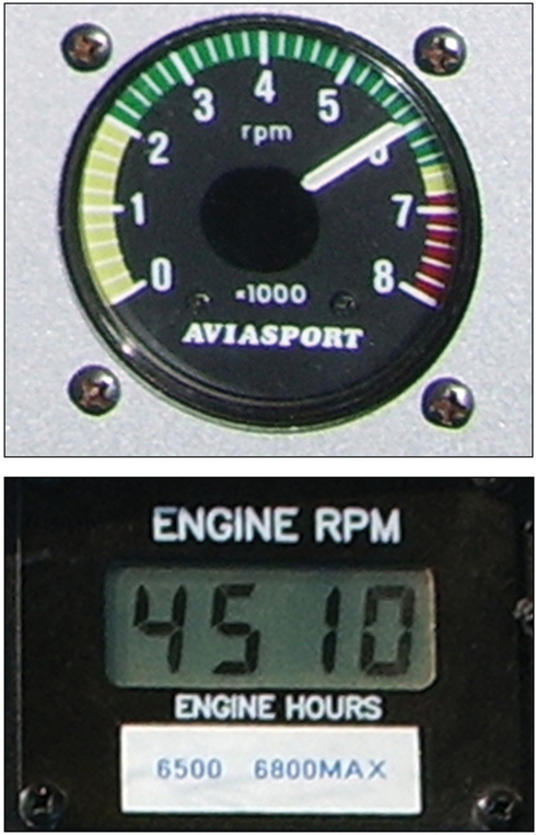
Figure 4-5. Engine RPM is indicated on the gauge.
mixture to the cylinder where combustion occurs. Outside air enters the induction system through an air filter on the engine. The air filter inhibits the entry of dust and other foreign objects. Two types of induction systems are used in powered parachute engines:
- The carburetor system is most common; it mixes the fuel and air in the carburetor before this mixture enters the engine intake, and
- The fuel injection system, which injects the fuel into the air just before entry into each cylinder.
PPCs use float-type carburetors. Reference the Pilot’s Operating Handbook of Aeronautical Knowledge for basics on float carburetor operation.
Modern two- and four-stroke carburetors operate with one of three jetting systems, depending on engine power. [Figure 4-6]When the throttle is closed, for engine idling, the throttle valve is closed and the fuel is supplied through the idle (pilot) jet and idle (pilot) air passage. The fuel/air/oil mixture is supplied to the cylinders through the bypass hole. [Figure 4-7]As the throttle is advanced and the throttle valve is raised, the fuel is sucked up through the main jet but is controlled by the opening and taper of the jet needle and needle jet. This is effective throughout most of the mid-range operation. About half throttle, the main jet size starts to influence the amount of fuel mixed with the air and this effect continues until it is the main influence at the highest throttle settings. [Figure 4-8]
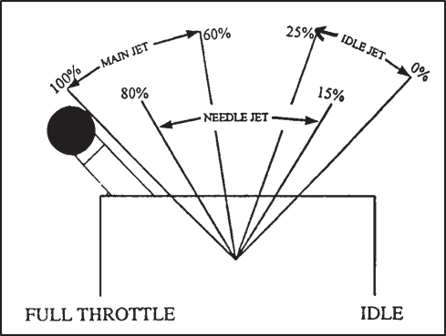
Figure 4-6. Throttle position and jetting system used.
As the throttle is advanced and the throttle valve is raised, the fuel is sucked up through the main jet but is controlled by the opening and taper of the jet needle and needle jet. This is effective throughout most of the mid-range operations. About half throttle, the main jet size starts to influence the amount of fuel mixed with the air and this effect continues until it is the main influence at the highest throttle settings. [Figure 4-8]
Two-Stroke Carburetor Jetting
Carburetors are normally set at sea-level pressure, with the jets and settings determined by the manufacturer. [Figure 4-9] However, as altitude increases, the
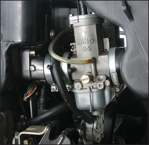
Figure 4-9. Typical 2-stroke carburetor.
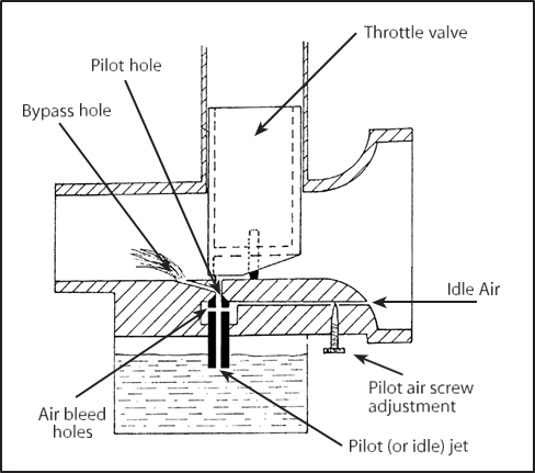
Figure 4-7. Pilot or Idle jet system.
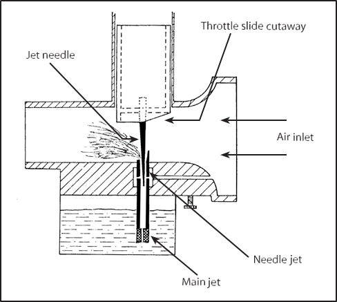
Figure 4-8. Jet needle/needle jet and main jet system.
density of air entering the carburetor decreases, while the density of the fuel remains the same. This creates a progressively richer mixture, the same fuel but less air, which can result in engine roughness and an appreciable loss of power. The roughness is usually due to spark plug fouling from excessive carbon buildup on the plugs. Carbon buildup occurs because the excessively rich mixture lowers the temperature inside the cylinder, inhibiting complete combustion of the fuel. This condition may occur at high-elevation airports and during climbs or cruise flight at high altitudes. To maintain the correct fuel-air mixture, you can change the main jets and the midrange jets setting for base operations at a high-density altitude airport. Operating from low-altitude airports and climbing to an altitude where the mixture becomes rich for short periods is OK.
Operating an aircraft at a lower altitude airport with the jets set for higher altitudes will create too lean of a mixture, heat up the engine, and cause the engine to seize. The pilot must be aware of the jetting for the machine to adjust the mixture. Consult your POH for specific procedures for setting jets at different al- titudes.
Four-stroke engines typically have automatic mixture control for higher altitudes or a mixture control that can be operated by the pilot.
One disadvantage of the carburetor system versus the fuel-injected system is its icing tendency. Carbure- tor ice occurs due to the effect of fuel vaporization and the decrease in air pressure in the venturi, which causes a sharp temperature drop in the carburetor. If water vapor in the air condenses when the carburetor temperature is at or below freezing, ice may form on internal surfaces of the carburetor, including the throttle valve.
Ice generally forms in the vicinity of the venturi throat. This restricts the flow of the fuel-air mixture and reduces power. If enough ice builds up, the engine may cease to operate. Carburetor ice is most likely to occur when temperatures are below 70°F (21°C) and the relative humidity is above 80 percent. However, due to the sudden cooling that takes place in the carburetor, icing can occur even with temperatures as high as 100°F (38°C) and humidity as low as 50 percent. This temperature drop can be as much as 60 to 70°F. Therefore, at an outside air temperature of 100°F, a temperature drop of 70°F results in an air temperature in the carburetor of 30°F. [Figure 4-10]
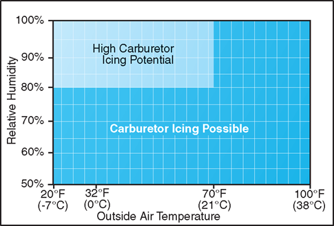
Figure 4-10. Although carburetor ice is most likely to form when the temperature and humidity are in ranges indicated by this chart, carburetor ice is also possible under conditions not depicted.
The first indication of carburetor icing in a powered parachute is a decrease in engine RPM, which may be followed by engine roughness. Although carburetor ice can occur during any phase of flight, it is particularly dangerous when using reduced power during a descent. Under certain conditions, carburetor ice could build unnoticed until you try to add power. To combat the effects of carburetor ice, some engines have a carb heat option. Some of the newer four-stroke engines have carburetor heat turned on all the time to combat icing. Two-stroke engines are typically less susceptible to icing but specific installations dictate how sus- ceptible the carburetor is to icing. Consult the aircraft POH for the probability of carb ice for the specific installation you have and for carb ice procedures.
In a fuel injection system, the fuel is injected either directly into the cylinders or just ahead of the intake valve. A fuel injection system usually incorporates these basic components: an engine-driven fuel pump, a fuel-air control unit, a fuel manifold (fuel distributor), discharge nozzles, an auxiliary fuel pump, and fuel pressure/flow indicators. [Figure 4-11]
The auxiliary fuel pump provides fuel under pressure to the fuel-air control unit for engine starting and/or emergency use. After starting, the engine-driven fuel pump provides fuel under pressure from the fuel tank to the fuel-air control unit. This control unit, which essentially replaces the carburetor, meters the fuel and sends it to the fuel manifold valve at a rate controlled by the throttle. After reaching the fuel manifold valve, the fuel is distributed to the individual fuel discharge nozzles. The discharge nozzles, which are located in each cylinder head, inject the fuel-air mixture directly into each cylinder intake port.
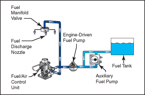
Figure 4-11. Fuel injection system.
Some of the advantages of fuel injection are:
- No carburetor icing.
- Better fuel flow.
- Faster throttle response.
- Precise control of mixture.
- Better fuel distribution.
- Easier cold weather starts. Disadvantages include:
- Difficulty in starting a hot engine.
- Vapor locks during ground operations on hot days.
- Problems associated with restarting an engine that quits because of fuel starvation.
Ignition System
The ignition system provides the spark that ignites the fuel-air mixture in the cylinders. Components include a magneto generator, an electronic control box that replaces mechanical points, spark plugs, high-voltage leads and the ignition switch(es). Individual manufacturer designs will vary and pilots must be familiar with the aircraft operating procedures for the PPC be- ing flown.
A magneto uses a permanent magnet to generate an electrical current independent of the aircraft’s electrical system which might include a battery. The aircraft electrical system can fail—the battery can go dead—however, this has no effect on the ignition system which uses a separate generator in the magneto. The electricity from the separate ignition coil on the magneto generator goes into the ignition control box where the correct voltage is produced and timed to fire the spark plugs at the proper time. The magneto also sends a signal to the electric control box to provide the timing signal to fire the spark plugs.
Most modern PPCs use an electronic timing system instead of the mechanical points inside the old magnetos which also housed the points. Capacitor discharge ignition (CDI) systems are a common example of an electronic ignition system. Electronic ignition systems operate without any moving parts to increase reliability and efficiency. A CDI system begins to fire when the starter is engaged and the crankshaft begins to turn. It continues to operate whenever the crankshaft is rotating.
Most powered parachutes incorporate a dual ignition system with two individual coil systems in the magneto, two individual electronic ignition timing systems (electric box), two separate sets of wires, and two spark plugs per cylinder. Dual ignition systems increase overall reliability of the engine. Each ignition system operates independently to fire one of the two spark plugs. If one ignition system fails, the other is unaffected. The engine will continue to operate normally, although you can expect a slight decrease in engine power.
The operation of the ignition system is controlled in the cockpit by the ignition switch(es). Since there are two individual ignition systems, there are normally two separate ignition toggle switches.
You can identify a malfunctioning ignition system during the pre-takeoff check by observing the decrease in RPM that occurs when you first turn off one ignition switch, turn it back on, and then turn off the other. A noticeable decrease in engine RPM is normal during this check. If the engine stops running when you switch to one ignition system or if the RPM drop exceeds the allowable limit, do not fly the powered parachute until the problem is corrected. The cause could be fouled plugs, broken or shorted wires between the magneto and the plugs, or improperly timed firing of the plugs because of the control box.
It should be noted that “no drop” in RPM is not normal, and in that instance, the powered parachute should not be flown. Following engine shutdown, keep the ignition switches in the OFF position. Even with the battery and master switches OFF, the engine can fire and turn over if you leave an ignition switch ON and the propeller is moved because the ignition system requires no outside source of electrical power. The potential for serious injury in this situation is ob- vious.
Combustion
During normal combustion, the fuel-air mixture burns in a very controlled and predictable manner. Although the process occurs in a fraction of a second, the mixture actually begins to burn at the point where it is ignited by the spark plugs, then burns away from the plugs until it is consumed completely. This type of combustion causes a smooth buildup of temperature and pressure and ensures that the expanding gases deliver the maximum force to the piston at exactly the right time in the power stroke.
Detonation is an uncontrolled, explosive ignition of the fuel-air mixture within the cylinder’s combustion chamber. It causes excessive temperatures and pressures which, if not corrected, can quickly lead to failure of the piston, cylinder, or valves. In less severe cases, detonation causes engine overheating, roughness, or loss of power.
Detonation is characterized by high cylinder head temperatures and is most likely to occur when operating at high power settings. Some common operational causes of detonation include:
- Using a lower fuel grade than that specified by the aircraft manufacturer or operate the engine after it has been sitting for an extended period; after 3 weeks or as indicated by
your POH you should drain old fuel out and replenish it with fresh fuel.
- Operating the engine at high power settings with an excessively lean mixture.
- Detonation also can be caused by extended ground operations.
Detonation may be avoided by following these basic guidelines during the various phases of ground and flight operations:
- Make sure the proper grade of fuel is being used. Drain and refuel if the fuel is old.
- Develop a habit of monitoring the engine instruments to verify proper operation according to procedures established by the manufacturer.
Preignition occurs when the fuel-air mixture ignites prior to the engine’s normal ignition event. Premature burning is usually caused by a residual hot spot in the combustion chamber, often created by a small carbon deposit on a spark plug, a cracked spark plug insula- tor, or other damage in the cylinder that causes a part to heat sufficiently to ignite the fuel-air charge. Preig- nition causes the engine to lose power, and produces high operating temperature. As with detonation, pre-ignition may also cause severe engine damage, be- cause the expanding gases exert excessive pressure on the piston while still on its compression stroke.
Detonation and preignition often occur simultaneously and one may cause the other. Since either condition causes high engine temperature accompanied by a decrease in engine performance, it is often difficult to distinguish between the two. Using the recommended grade of fuel and operating the engine within its proper temperature and RPM ranges reduce the chance of detonation or preignition.
Fuel Systems
The fuel system is designed to provide an uninterrupted flow of clean fuel from the fuel tank to the engine. See Chapter 3 for more information on fuel tanks. The
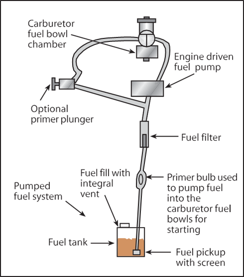
Figure 4-12. Fuel pump system.
fuel must be available to the engine under all conditions of engine power, altitude, attitude, and during all approved flight maneuvers. [Figure 4-12]
Powered parachutes have fuel pump systems. The main pump system is engine-driven and sometimes an electrically-driven auxiliary pump is provided for use in engine starting and in the event the engine pump fails. The auxiliary pump, also known as a boost pump, provides added reliability to the fuel system. The electrically driven auxiliary pump is controlled by a switch in the cockpit.
A diaphragm pump is the primary pump in the fuel system for two-stroke engines. Air pulses in the crankcase actuate a diaphragm and provide fuel under pressure to the carburetor. Four-stroke engines have a mechanical pump driven directly off the engine.
The fuel plunger primer is used to draw fuel from the tanks to supply it directly into the cylinders prior to starting the engine. This is particularly helpful during cold weather when engines are hard to start because there is not enough heat available to vaporize the fuel in the carburetor. For some powered parachutes, it is the only way to deliver fuel to the engine when first starting. After the engine starts and is running, the fuel pump pushes fuel to the carburetors and begins normal fuel delivery. To avoid overpriming, read the priming instructions in your POH for your powered parachute.
A choke or fuel enrichening system is an alternate method to provide additional fuel to the engine for initial cold starting. Actuating the choke control allows more fuel to flow into the carburetor.
The fuel bulb primer is manually actuated by squeezing the bulb to draw fuel from the tanks. This charges the fuel lines and carburetor float bowls before starting the engine the first time on a given day. After the engine starts, the fuel pump is able to deliver the fuel to the fuel bowls.
The fuel quantity gauge indicates the amount of fuel measured by a sensing unit in each fuel tank and is displayed in gallons. Do not depend solely on the ac- curacy of the fuel quantity gauge. Always visually check the fuel level in the tank during the preflight inspection, and then compare it with the corresponding fuel quantity indication. It is also important to track your inflight fuel consumption. Be sure to consult the POH for your powered parachute and know the ap- proximate consumption rate to ensure sufficient fuel for your flight.
If an auxiliary electric fuel pump is installed in the fuel system, a fuel pressure gauge is sometimes included. This gauge indicates the pressure in the fuel lines. The normal operating pressure can be found in the POH.
After leaving the fuel tank, the fuel passes through a filter before it enters the fuel pump or carburetor. This filter removes sediments that might be in the fuel.
Fuel
Aviation gasoline, or AVGAS, is identified by an octane or performance number (grade), which designates the antiknock value or knock resistance of the fuel mixture in the engine cylinder. The higher the grade of gasoline, the more pressure the fuel can withstand without detonating. Lower grades of fuel are used in lower-compression engines because these fuels ignite at a lower temperature. Higher grades are used in higher-compression engines because they must ignite at higher temperatures, but not prematurely. If the proper grade of fuel is not available, use the next higher grade as a substitute. Never use a lower grade. This can cause the cylinder head temperature to exceed its normal operating range, which may result in detonation.
Unfortunately, aviation gasoline or AVGAS 100LL is not recommended by at least one of the major two-stroke engine manufacturers. Even though the “LL” stands for “Low Lead,” 100LL contains more lead than the old premium leaded gas dispensed at automotive filling stations. The lead in the fuel leaves deposits in the piston ring grooves, freezing the rings in position and reducing engine performance.
Spark plugs are also very susceptible to lead foul- ing. This is especially true in two-stroke engines that use cooler ignition temperatures than standard aircraft engines.
AVGAS does have some advantages. It degrades slower than regular gas, maintaining its efficiency for a full 3 months. AVGAS 100LL has no seasonal or regional variations and is manufactured according to a standardized “recipe” worldwide.
If the airport has only 100LL available, it is permissible, absent any limitations of the engine manufacturer, to mix 100LL and 89 octane gasoline, for use in two-stroke engines. A 50-50 ratio will boost the octane rating and limit the amount of lead available for fouling. Generally speaking, this is a reasonable compromise when 89 octane is not available.
Two-stroke engine manufacturers, and four-stroke engines used on powered parachutes, typically recommend the use of 89 octane minimum auto fuel for their engines. Additives are put into auto gas primarily to reduce harmful emissions rather than boost performance. The additives are supposed to be listed at the pump, but the accuracy of this posting should be questioned.
Methanol alcohol has corrosive properties and can damage engines. Engine manufacturers do not recommend more than 3 percent methanol in fuel. Consult the POH for specifics on your engine.
Ethanol alcohol is less corrosive than methanol. However, it attracts water and is not as economical as gasoline. Ethanol does not get very good fuel economy. Avoid fuels with any more than 10 percent of ethanol in it. Consult your POH for specifics on your engine.
Manufacturers provide specific recommendations for the percentage of alcohol in fuel. The posting on the pump may not be accurate and alcohol content can vary greatly between fuel brands and stations. Additionally, higher percentages of alcohol will be added to autogas in the future. A simple test can be conducted to measure the fuel’s alcohol content to ensure the fuel you use stays within the manufacturer’s recommendations.
Use a general aviation sump collector, which includes graduation marks. Add water to a specific mark. Then add fuel to fill the collector up to the line for gas. Cover the top and shake it vigorously. After it settles, the water and alcohol will combine and it will look like there is now more water in the sump collector. The difference between the initial amount of water you first put into the collector and the new level of combined water and alcohol equals the amount of alcohol in the fuel. Compare this amount of alcohol and the amount of fuel to determine the percentage of alcohol
content in the fuel.
Methyl Tertiary Butyl Ether (MTBE) does not have the corrosive or water-attractive properties of the previously mentioned additives and is added to fuel to improve air quality. It has been banned in several states because it is carcinogenic and has been found in groundwater. It does not attract water, but it is expensive, so you will find it only in some of the better-grade fuels.
Clean fuel is imperative for the safe operation of a PPC. Of the accidents attributed to powerplant failure from fuel contamination, most have been traced to:
- Failure to remove contamination from the fuel
- Servicing aircraft with improperly filtered fuel
- Storing aircraft with partially filled fuel tanks.
- Lack of proper maintenance.
Rust is common in metal fuel containers and is a common fuel contaminant. Metal fuel tanks should be filled after each flight, or at least after the last flight of the day to prevent moisture condensation within the tank. Another way to prevent fuel contamination is to avoid refueling from cans and drums. Use a water filtering funnel or a funnel with a chamois skin when refueling from cans or drums. However, the use of a chamois will not always ensure decontaminated fuel. Worn-out chamois will not filter water; neither will a new, clean chamois that is already water-wet or damp. Most imitation chamois skins will not filter water.
Bad Gasoline
Letting fuel sit for weeks without using it will cause it to go bad. Even if gas does not go bad, it will often lose its octane with time. For those that premix gasoline and two-stroke oil, there is another set of problems. Fuel and oil are normally mixed at a 50:1 ratio. If premixed gas sits in a plastic container for a while, the gas will evaporate out leaving a richer oil mixture in the container. In any case, fresh gas should be used as much as possible.
Never mix oil and fuel in an enclosed area. Not only are the fumes irritating, but with the right fuel-air mixture, you can cause an explosion. Do all oil and gas mix outside? Refueling from fuel cans should also be done outside. Never smoke while refueling.
Be careful refueling an aircraft that has just landed. There is the danger of spilling fuel on a hot engine component, particularly an exhaust system component.
Refueling should be done using only safety-approved fuel containers. The fuel containers should be marked with the type of fuel stored in them. Confusing pre-mixed fuel and fuel that has no oil in it can be disastrous.
There are advantages to both metal and plastic containers. Metal cans won’t allow the sun’s ultraviolet rays in to harm the fuel. It also won’t develop static charges like a plastic container may. However, a metal can will be more prone to sweating when going from cool to warm temperatures on humid days. Metal cans and metal gas tanks are best kept either empty or full of fuel to leave no room for moist air.
Plastic fuel containers are easy to handle, inexpensive, available at discount stores, and do not scratch the finish on airframes. Plastic cans also do not sweat, so they don’t need to be stored topped off. However, fuel does deteriorate a little faster in plastic. Also, plastic containers can get charged with static electricity while sliding around in the bed of a pickup truck, especially if the truck has a plastic bed liner. Many states now have laws prohibiting people from filling plastic containers unless first placed on the ground.
Static electricity can also be formed by the friction of air passing over the surfaces of a powered parachute in flight and by the flow of fuel through the hose and nozzle during refueling if fueling at a pump. Nylon, Dacron, and wool clothing are especially prone to accumulate and discharge static electricity from the person to the funnel or nozzle. To guard against the possibility of static electricity igniting fuel fumes, a ground wire should be attached to the aircraft before the fuel cap is removed from the tank. The refueling nozzle should then be grounded to the aircraft before refueling is begun, and should remain grounded throughout the refueling process.
The passage of fuel through a chamois increases the charge of static electricity and the danger of sparks. The aircraft must be properly grounded and the nozzle, chamois filter, and funnel bonded to the aircraft. If a can is used, it should be connected to either the grounding post or the funnel. Cell phones should not be used while refueling as they could pose a fire risk.
Mixing Two-Stroke Oil and Fuel
Two-stroke engines require special two-stroke oil to be mixed into the fuel before reaching the cylinder of the engine. In some engines, an oil injection pump is used to deliver the exact amount of oil into the intake of the engine depending on the throttle setting. An advantage of an oil injection system is pilots don’t have to premix any oil into the fuel. However, an important preflight check is to make sure the two-stroke oil reservoir is properly filled.
If a two-stroke engine doesn’t have an oil injection system, it is critical to mix oil into fuel before it is put into the tank. Just pouring oil into the fuel tank doesn’t give it the proper chance to mix with the gas and makes it difficult to measure the proper amount of oil for mixing. To mix two-stroke oil you should:
- Find a clean, approved container. Pour a little gas into it to help pre-dilute the two-stroke oil.
- Pour in a known amount of two-stroke oil into the container. Oil should be approved for air-cooled engines at a 50:1 mixing ratio (check the engine manufacturer for proper fuel-to-oil ratio for your PPC). Use a measuring cup if necessary. Shake the oil-gas mixture around a little to dilute the oil with gasoline.
- Add gasoline until the 50:1 ratio is reached. If you choose to use a water-separating funnel, make sure the funnel is grounded or at least in contact with the fuel container.
- Put the cap on the fuel can and shake the gasoline and oil mixture thoroughly.
Starting System
Most small aircraft use a direct-cranking electric starter system. This system consists of a source of electricity, wiring, switches, and solenoids to operate the starter and a starter motor. The starter engages the aircraft flywheel or the gearbox, rotating the engine at a speed that allows the engine to start and maintain operation.
Electrical power for starting is usually supplied by an on-board battery. When the battery switch is turned on, electricity is supplied to the main power bus through the battery solenoid. Both the starter and the starter switch draw current from the main bus, but the starter will not operate until the starting solenoid is energized by the starter switch being turned to the “start” position. When the starter switch is released from the “start” position, the solenoid removes power from the starter motor. The starter motor is protected from being driven by the engine through a clutch in the starter drive that allows the engine to run faster than the starter motor.
Oil Systems
In a four-stroke engine, the engine oil system performs several important functions, including:
- Lubrication of the engine’s moving parts.
- Cooling of the engine by reducing friction.
- Removing heat from the cylinders.
- Providing a seal between the cylinder walls and pistons.
- Carrying away contaminants.
Four-stroke engines use either a wet-sump or drysump oil system. Refer to Chapter 5 of the Pilot’s Handbook of Aeronautical Knowledge for more information on four-stroke oil systems.
Engine Cooling Systems
The burning fuel within the cylinders produces intense heat, most of which is expelled through the exhaust system. Much of the remaining heat, however, must be removed, or at least dissipated, to prevent the engine from overheating.
While the oil system in a four-stroke engine and the fuel-oil mix in a two-stroke engine is vital to the internal cooling of the engine, an additional method of cooling is necessary for the engine’s external surface. Powered parachute engines operate with either air-cooled or liquid-cooled systems.
Many powered parachutes are equipped with a cylinder head temperature (CHT) gauge. This instrument indicates a direct and immediate cylinder temperature change. This instrument is calibrated in degrees Celsius or Fahrenheit. Proper CHT ranges can be found in the pilot’s operating handbook for that machine.
Air cooling is accomplished by air being pulled into the engine shroud by a cooling fan. Baffles route this air over fins attached to the engine cylinders where the air absorbs the engine heat. Expulsion of the hot air takes place through one or more openings in the shroud. If cylinder head temperatures rise too much in an air-cooled engine, it is because of lubrication problems: cooling fan drive belt damage or wear, or air blockage in the cooling fins by a bird or insect nest.
Liquid cooling systems pump coolant through jackets in the cylinders and head. The heated liquid is then routed to a radiator where the heat is radiated to the atmosphere. The cooled liquid is then returned to the engine. If the radiator is mounted low and close to the propeller, the propeller can constantly move air across the radiator and keep the engine cool even when the powered parachute is not moving. Radiators mounted high and away from the propeller raise the center of gravity and make it more difficult for the radiator to cool the engine unless the powered parachute is moving. Breaking in an engine through ground runs on a hot day is when radiator placement is most critical.
Liquid-cooled engines can overheat for a number of reasons, such as coolant not at proper levels, a leak, a failed water pump, or a blockage of the radiator. Operating an engine above its maximum design temperature can cause a loss of power and detonation. It will also lead to serious permanent damage, such as scoring the cylinder walls and damaging the pistons and rings. Monitor the engine temperature instruments to avoid high operating temperatures.
Operating the engine lower than its designed temperature range can cause piston seizure and scarring on the cylinder walls. This happens most often in liquid-cooled powered parachutes in cold weather where large radiators designed for summer flying may need to be partially blocked off.


