Helicopters and gyroplanes both achieve lift through the use of airfoils, and, therefore, many of the basic aerodynamic principles governing the production of lift apply to both aircraft. These concepts are explained in depth in Chapter 2—General Aerodynamics, and constitute the foundation for discussing the aerodynamics of a gyroplane.
Autorotation
A fundamental difference between helicopters and gyroplanes is that in powered flight, a gyroplane rotor system operates in autorotation. This means the rotor spins freely as a result of air flowing up through the blades, rather than using engine power to turn the blades and draw air from above. [Figure 16-1] Forces are created during autorotation that keep the rotor blades turning, as well as creating lift to keep the air- craft aloft. Aerodynamically, the rotor system of a gyroplane in normal flight operates like a helicopter rotor during an engine-out forward autorotative descent.
VERTICAL AUTOROTATION
During a vertical autorotation, two basic components contribute to the relative wind striking the rotor blades. [Figure 16-2] One component, the upward flow of air through the rotor system, remains relatively constant for a given flight condition. The other component is the rotational airflow, which is the wind velocity across the blades as they spin. This component varies significantly based upon how far from the rotor hub it is measured. For example, consider a rotor disc that is 25 feet in diameter operating at 300 r.p.m. At a point one foot outboard from the rotor hub, the blades are traveling in a circle with a circumference of 6.3 feet. This equates to 31.4 feet per second (f.p.s.), or a rotational blade speed of 21 m.p.h. At the blade tips, the circumference of the circle increases to 78.5 feet. At the same operating speed of 300 r.p.m., this creates a blade tip
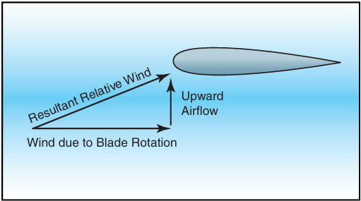
Figure 16-2. In a vertical autorotation, the wind from the rotation of the blade combines with the upward airflow to produce the resultant relative wind striking the airfoil.
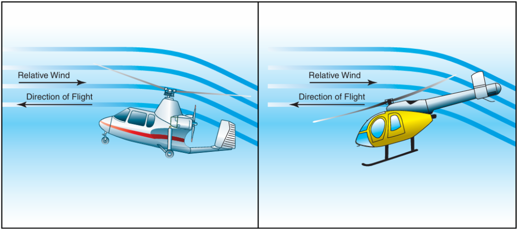
Figure 16-1. Airflow through the rotor system on a gyroplane is reversed from that on a powered helicopter. This airflow is the medium through which power is transferred from the gyroplane engine to the rotor system to keep it rotating.
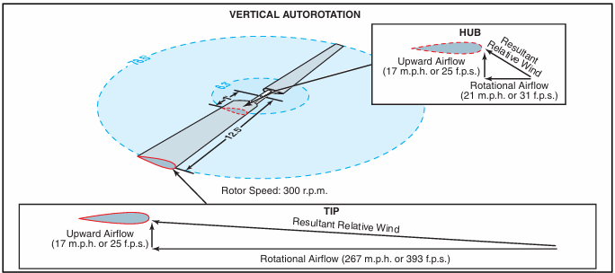
Figure 16-3. Moving outboard on the rotor blade, the rotational velocity increasingly exceeds the upward component of airflow, resulting in a higher relative wind at a lower angle of attack.
speed of 393 feet per second, or 267 m.p.h. The result is a higher total relative wind, striking the blades at a lower angle of attack. [Figure 16-3]
ROTOR DISC REGIONS
As with any airfoil, the lift that is created by rotor blades is perpendicular to the relative wind. Because the relative wind on rotor blades in autorotation shifts from a high angle of attack inboard to a lower angle of attack outboard, the lift generated has a higher forward component closer to the hub and a higher vertical com- ponent toward the blade tips. This creates distinct regions of the rotor disc that create the forces necessary for flight in autorotation. [Figure 16-4] The autorotative region, or driving region, creates a total aerodynamic force with a forward component that exceeds all rearward drag forces and keeps the blades spinning. The propeller region, or driven region, generates a total aerodynamic force with a higher vertical component that allows the gyroplane to remain aloft. Near the center of the rotor disc is a stall region where the rotational component of the relative wind is so low that the resulting angle of attack is beyond the stall limit of the airfoil. The stall region creates drag against the direction of rotation that must be overcome by the forward acting forces generated by the driving region.
AUTOROTATION IN FORWARD FLIGHT
As discussed thus far, the aerodynamics of autorotation apply to a gyroplane in a vertical descent. Because gyroplanes are normally operated in forward flight, the component of relative wind striking the rotor blades as a result of forward speed must also be considered. This component has no effect on the aerodynamic principles that cause the blades to autorotate, but causes a shift in the zones of the rotor disc.
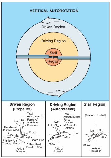
Figure 16-4. The total aerodynamic force is aft of the axis of rotation in the driven region and forward of the axis of rotation in the driving region. Drag is the major aerodynamic force in the stall region. For a complete depiction of force vectors during a vertical autorotation, refer to Chapter 3— Aerodynamics of Flight (Helicopter), Figure 3-22.
As a gyroplane moves forward through the air, the for- ward speed of the aircraft is effectively added to the relative wind striking the advancing blade, and subtracted from the relative wind striking the retreating blade. To prevent uneven lifting forces on the two sides of the rotor disc, the advancing blade teeters up, decreasing angle of attack and lift, while the retreating blade teeters down, increasing angle of attack and lift. (For a complete discussion on dissymmetry of lift, refer to Chapter 3—Aerodynamics of Flight.) The lower angles of attack on the advancing blade cause more of the blade to fall in the driven region, while higher angles of attack on the retreating blade cause more of the blade to be stalled. The result is a shift in the rotor regions toward the retreating side of the disc to a degree directly related to the forward speed of the aircraft. [Figure 16-5]
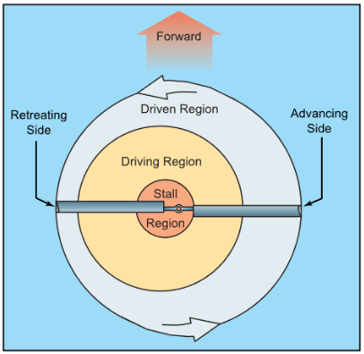
Figure 16-5. Rotor disc regions in forward autorotative flight.
REVERSE FLOW
On a rotor system in forward flight, reverse flow occurs near the rotor hub on the retreating side of the rotor disc. This is the result of the forward speed of the air- craft exceeding the rotational speed of the rotor blades. For example, two feet outboard from the rotor hub, the blades travel in a circle with a circumference of 12.6 feet. At a rotor speed of 300 r.p.m., the blade speed at the two-foot station is 42 m.p.h. If the aircraft is being operated at a forward speed of 42 m.p.h., the forward speed of the aircraft essentially negates the rotational velocity on the retreating blade at the two-foot station. Moving inboard from the two-foot station on the retreating blade, the forward speed of the aircraft increasingly exceeds the rotational velocity of the blade. This causes the airflow to actually strike the trailing edge of the rotor blade, with velocity increasing toward the rotor hub. [Figure 16-6] The size of the area that experiences reverse flow is dependent primarily on the forward speed of the aircraft, with higher speed creating a larger region of reverse flow. To some degree, the operating speed of the rotor system also has an effect on the size of the region, with systems operating at lower r.p.m. being more susceptible to reverse flow and allowing a greater portion of the blade to experience the effect.
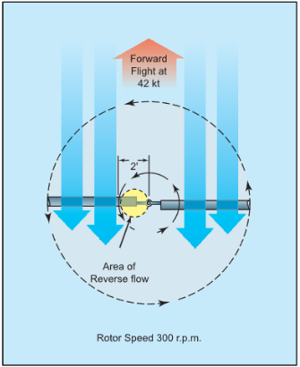
Figure 16-6. An area of reverse flow forms on the retreating blade in forward flight as a result of aircraft speed exceeding blade rotational speed.
RETREATING BLADE STALL
The retreating blade stall in a gyroplane differs from that of a helicopter in that it occurs outboard from the rotor hub at the 20 to 40 percent position rather than at the blade tip. Because the gyroplane is operating in autorotation, in forward flight there is an inherent stall region centered inboard on the retreating blade. [Refer to figure 16-5] As forward speed increases, the angle of attack on the retreating blade increases to prevent dis- symmetry of lift and the stall region moves further outboard on the retreating blade. Because the stalled portion of the rotor disc is inboard rather than near the tip, as with a helicopter, less force is created about the aircraft center of gravity. The result is that you may feel a slight increase in vibration, but you would not experience a large pitch or roll tendency.
Rotor force
As with any heavier than air aircraft, the four forces acting on the gyroplane in flight are lift, weight, thrust and drag. The gyroplane derives lift from the rotor and
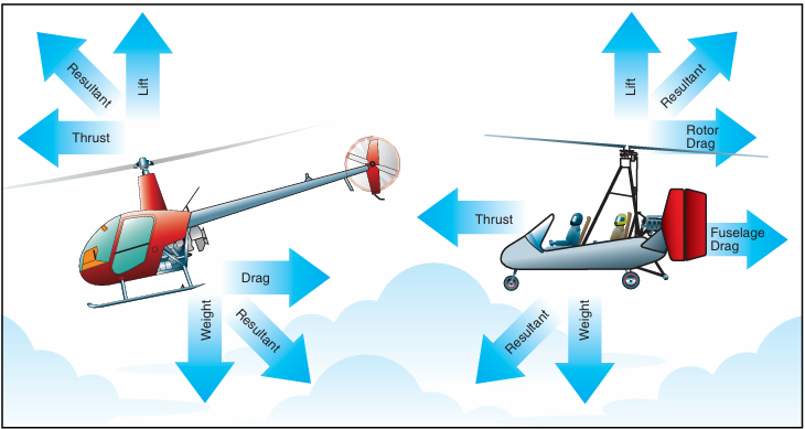
Figure 16-7. Unlike a helicopter, in forward powered flight the resultant rotor force of a gyroplane acts in a rearward direction.
thrust directly from the engine through a propeller. [Figure 16-7]
The force produced by the gyroplane rotor may be divided into two components; rotor lift and rotor drag. The component of rotor force perpendicular to the flight path is rotor lift, and the component of rotor force parallel to the flight path is rotor drag. To derive the total aircraft drag reaction, you must also add the drag of the fuselage to that of the rotor.
ROTOR LIFT
Rotor lift can most easily be visualized as the lift required to support the weight of the aircraft. When an airfoil produces lift, induced drag is produced. The most efficient angle of attack for a given airfoil pro- duces the most lift for the least drag. However, the air- foil of a rotor blade does not operate at this efficient angle throughout the many changes that occur in each revolution. Also, the rotor system must remain in the autorotative (low) pitch range to continue turning in order to generate lift.
Some gyroplanes use small wings for creating lift when operating at higher cruise speeds. The lift provided by the wings can either supplement or entirely replace rotor lift while creating much less induced drag.
ROTOR DRAG
Total rotor drag is the summation of all the drag forces acting on the airfoil at each blade position. Each blade position contributes to the total drag according to the speed and angle of the airfoil at that position. As the rotor blades turn, rapid changes occur on the airfoils depending on position, rotor speed, and aircraft speed. A change in the angle of attack of the rotor disc can effect a rapid and substantial change in total rotor drag.
Rotor drag can be divided into components of induced drag and profile drag. The induced drag is a product of lift, while the profile drag is a function of rotor r.p.m. Because induced drag is a result of the rotor providing lift, profile drag can be considered the drag of the rotor when it is not producing lift. To visualize profile drag, consider the drag that must be overcome to prerotate the rotor system to flight r.p.m. while the blades are producing no lift. This can be achieved with a rotor system having a symmetrical airfoil and a pitch change capability by setting the blades to a 0° angle of attack. A rotor system with an asymmetrical airfoil and a built in pitch angle, which includes most amateur-built teeter-head rotor systems, cannot be prerotated without having to overcome the induced drag created as well.
Thrust
Thrust in a gyroplane is defined as the component of total propeller force parallel to the relative wind. As with any force applied to an aircraft, thrust acts around the center of gravity. Based upon where the thrust is applied in relation to the aircraft center of gravity, a relatively small component may be perpendicular to the relative wind and can be considered to be additive to lift or weight.
In flight, the fuselage of a gyroplane essentially acts as a plumb suspended from the rotor, and as such, it is subject to pendular action in the same way as a helicopter. Unlike a helicopter, however, thrust is applied directly to the airframe of a gyroplane rather than being obtained through the rotor system. As a result, different forces act on a gyroplane in flight than on a helicopter. Engine torque, for example, tends to roll the fuselage in the direction opposite propeller rotation, causing it to be deflected a few degrees out of the vertical plane. [Figure 16-8] This slight “out of vertical” condition is usually negligible and not considered relevant for most flight operations.
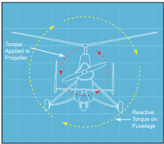
Figure 16-8. Engine torque applied to the propeller has an equal and opposite reaction on the fuselage, deflecting it a few degrees out of the vertical plane in flight.
Stability
Stability is designed into aircraft to reduce pilot work- load and increase safety. A stable aircraft, such as a typical general aviation training airplane, requires less attention from the pilot to maintain the desired flight attitude, and will even correct itself if disturbed by a gust of wind or other outside forces. Conversely, an unstable aircraft requires constant attention to maintain control of the aircraft.
Pendular Action—The lateral or longitudinal oscillation of the fuselage due to it being suspended from the rotor system. It is similar to the action of a pendulum.
Pendular action is further dis- cussed in Chapter 3— Aerodynamics of Flight.
There are several factors that contribute to the stability of a gyroplane. One is the location of the horizontal stabilizer. Another is the location of the fuselage drag in relation to the center of gravity. A third is the inertia moment around the pitch axis, while a fourth is the relation of the propeller thrust line to the vertical location of the center of gravity (CG). However, the one that is probably the most critical is the relation of the rotor force line to the horizontal location of the center of gravity.
HORIZONTAL STABILIZER
A horizontal stabilizer helps in longitudinal stability, with its efficiency greater the further it is from the center of gravity. It is also more efficient at higher airspeeds because lift is proportional to the square of the airspeed. Since the speed of a gyroplane is not very high, manufacturers can achieve the desired stability by varying the size of the horizontal stabilizer, chang- ing the distance it is from the center of gravity, or by placing it in the propeller slipstream.
FUSELAGE DRAG (CENTER OF PRESSURE)
If the location, where the fuselage drag or center of pressure forces are concentrated, is behind the CG, the gyroplane is considered more stable. This is espe- cially true of yaw stability around the vertical axis. However, to achieve this condition, there must be a sufficient vertical tail surface. In addition, the gyro- plane needs to have a balanced longitudinal center of pressure so there is sufficient cyclic movement to prevent the nose from tucking under or lifting, as pressure builds on the frontal area of the gyroplane as airspeed increases.
PITCH INERTIA
Without changing the overall weight and center of gravity of a gyroplane, the further weights are placed from the CG, the more stable the gyroplane. For exam- ple, if the pilot’s seat could be moved forward from the CG, and the engine moved aft an amount, which keeps the center of gravity in the same location, the gyroplane becomes more stable. A tightrope walker applies this same principle when he uses a long pole to balance himself.
PROPELLER THRUST LINE
Considering just the propeller thrust line by itself, if the thrust line is above the center of gravity, the gyroplane has a tendency to pitch nose down when power is applied, and to pitch nose up when power is removed. The opposite is true when the propeller thrust line is below the CG. If the thrust line goes through the CG or
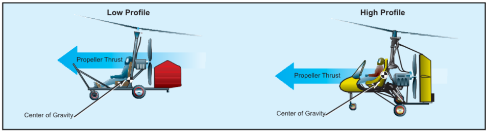
Figure 16-9. A gyroplane which has the propeller thrust line above the center of gravity is often referred to as a low profile gyro
plane. One that has the propeller thrust line below or at the CG is considered a high profile gyroplane.
nearly so there is no tendency for the nose to pitch up or down. [Figure 16-9]
ROTOR FORCE
Because some gyroplanes do not have horizontal stabi- lizers, and the propeller thrust lines are different, gyro- plane manufacturers can achieve the desired stability by placing the center of gravity in front of or behind the rotor force line. [Figure 16-10]
Suppose the CG is located behind the rotor force line in forward flight. If a gust of wind increases the angle of attack, rotor force increases. There is also an increase in the difference between the lift produced on the advancing and retreating blades. This increases the flapping angle and causes the rotor to pitch up. This pitching action increases the moment around the center of gravity, which leads to a greater increase in the angle of attack. The result is an unstable condition.
If the CG is in front of the rotor force line, a gust of wind, which increases the angle of attack, causes the rotor disc to react the same way, but now the increase in rotor force and blade flapping decreases the moment. This tends to decrease the angle of attack, and creates a stable condition.
TRIMMED CONDITION
As was stated earlier, manufacturers use a combination of the various stability factors to achieve a trimmed gyroplane. For example, if you have a gyroplane where the CG is below the propeller thrust line, the propeller thrust gives your aircraft a nose down pitching moment when power is applied. To compensate for this pitching moment, the CG, on this type of gyroplane, is usually located behind the rotor force line. This location pro- duces a nose up pitching moment.
Conversely, if the CG is above the propeller thrust line, the CG is usually located ahead of the rotor force line. Of course, the location of fuselage drag, the pitch inertia, and the addition of a horizontal stabilizer can alter where the center of gravity is placed.
Blade Flapping—The upward or downward movement of the rotor- blades during rotation.
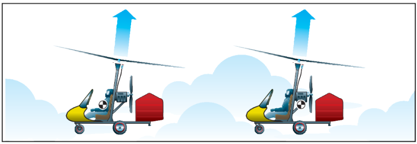
Figure 16-10. If the CG is located in front of the rotor force line, the gyroplane is more stable than if the CG is located behind the rotor force line.


