Attitude instrument flying in helicopters is essentially visual flying with the flight instruments substituted for the various reference points on the helicopter and the natural horizon. Control changes, required to produce a given attitude by reference to instruments, are identical to those used in helicopter VFR flight, and your thought processes are the same. Basic instrument training is intended as a building block towards attaining an instrument rating. It will also enable you to do a 180° turn in case of inadvertent incursion into instrument meteorological conditions (IMC).
FLIGHT INSTRUMENTS
When flying a helicopter with reference to the flight instruments, proper instrument interpretation is the basis for aircraft control. Your skill, in part, depends on your understanding of how a particular instrument or system functions, including its indications and limita-tions. With this knowledge, you can quickly determine what an instrument is telling you and translate that information into a control response.
PITOT-STATIC INSTRUMENTS
The pitot-static instruments, which include the airspeed indicator, altimeter, and vertical speed indicator, operate on the principle of differential air pressure. Pitot pressure, also called impact, ram, or dynamic pressure, is directed only to the airspeed indicator, while static pressure, or ambient pressure, is directed to all three instruments. An alternate static source may be included allowing you to select an alternate source of ambient pressure in the event the main port becomes blocked. [Figure 12-1]
AIRSPEED INDICATOR
The airspeed indicator displays the speed of the helicopter through the air by comparing ram air pressure from the pitot tube with static air pressure from the static port-the greater the differential, the greater the speed. The instrument displays the result of this pressure differential as indicated airspeed (IAS).
Manufacturers use this speed as the basis for determining helicopter performance, and it may be displayed in knots, miles per hour, or both. [Figure 12-2] When an indicated airspeed is given for a particular situation, you normally use that speed without making a correction for altitude or temperature. The reason no correction is needed is that an airspeed indicator and aircraft performance are affected equally by changes in air den-sity. An indicated airspeed always yields the same performance because the indicator has, in fact, compensated for the change in the environment.

Figure 12-1. Ram air pressure is supplied only to the airspeed indicator, while static pressure is used by all three instruments. Electrical heating elements may be installed to prevent ice from forming on the pitot tube. A drain opening to remove moisture is normally included.
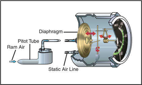
Figure 12-2. Ram air pressure from the pitot tube is directed to a diaphragm inside the airspeed indicator. The airtight case is vented to the static port. As the diaphragm expands or contracts, a mechanical linkage moves the needle on the face of the indicator.
INSTRUMENT CHECK—During the preflight, ensure that the pitot tube, drain hole, and static ports are unobstructed. Before liftoff, make sure the airspeed indicator is reading zero. If there is a strong wind blowing directly at the helicopter, the airspeed indicator may read higher than zero, depending on the wind speed and direction. As you begin your takeoff, make sure the airspeed indicator is increasing at an appropriate rate. Keep in mind, however, that the airspeed indication might be unreliable below a certain airspeed due to rotor downwash.
ALTIMETER
The altimeter displays altitude in feet by sensing pressure changes in the atmosphere. There is an adjustable barometric scale to compensate for changes in atmospheric pressure. [Figure 12-3]

Figure 12-3. The main component of the altimeter is a stack of sealed aneroid wafers. They expand and contract as atmospheric pressure from the static source changes. The mechanical linkage translates these changes into pointer movements on the indicator.
The basis for altimeter calibration is the International Standard Atmosphere (ISA), where pressure, tempera-ture, and lapse rates have standard values. However, actual atmospheric conditions seldom match the standard values. In addition, local pressure readings within a given area normally change over a period of time, and pressure frequently changes as you fly from one area to another. As a result, altimeter indications are subject to errors, the extent of which depends on how much the pressure, temperature, and lapse rates deviate from stan-dard, as well as how recently you have set the altimeter.
The best way to minimize altimeter errors is to update the altimeter setting frequently. In most cases, use the current altimeter setting of the nearest reporting station along your route of flight per regulatory requirements.
INSTRUMENT CHECK--During the preflight, ensure that the static ports are unobstructed. Before lift-off, set the altimeter to the current setting. If the altimeter indicates within 75 feet of the actual elevation, the altimeter is generally considered acceptable for use.
VERTICAL SPEED INDICATOR
The vertical speed indicator (VSI) displays the rate of climb or descent in feet per minute (f.p.m.) by measuring how fast the ambient air pressure increases or decreases as the helicopter changes altitude. Since the VSI measures only the rate at which air pressure changes, air temperature has no effect on this instru-ment. [Figure 12-4]

Figure 12-4. Although the sealed case and diaphragm are both connected to the static port, the air inside the case is restricted through a calibrated leak. When the pressures are equal, the needle reads zero. As you climb or descend, the pressure inside the diaphragm instantly changes, and the needle registers a change in vertical direction. When the pressure differential stabilizes at a definite ratio, the needle registers the rate of altitude change.
There is a lag associated with the reading on the VSI, and it may take a few seconds to stabilize when showing rate of climb or descent. Rough control technique and turbulence can further extend the lag period and cause erratic and unstable rate indications. Some aircraft are equipped with an instantaneous vertical speed indicator (IVSI), which incorporates accelerometers to compensate for the lag found in the typical VSI.
INSTRUMENT CHECK-During the preflight, ensure that the static ports are unobstructed. Check to see that the VST is indicating zero before lift-off. During takeoff, check for a positive rate of climb indication.
SYSTEM ERRORS
The pitot-static system and associated instruments are usually very reliable. Errors are generally caused when the pitot or static openings are blocked. This may be caused by dirt, ice formation, or insects. Check the pitot and static openings for obstructions during the preflight.
It is also advisable to place covers on the pitot and static ports when the helicopter is parked on the ground.
The airspeed indicator is the only instrument affected by a blocked pitot tube. The system can become clogged in two ways. If the ram air inlet is clogged, but the drain hole remains open, the airspeed indicator registers zero, regardless of airspeed. If both the ram air inlet and the drain hole become blocked, pressure in the line is trapped, and the airspeed indicator reacts like an altimeter, showing an increase in airspeed with an increase in altitude, and a decrease in speed as altitude decreases. This occurs as long as the static port remains unobstructed.
If the static port alone becomes blocked, the airspeed indicator continues to function, but with incorrect read-ings. When you are operating above the altitude where the static port became clogged, the airspeed indicator reads lower than it should. Conversely, when operating below that altitude, the indicator reads higher than the correct value. The amount of error is proportional to the distance from the altitude where the static system became blocked. The greater the difference, the greater the error. With a blocked static system, the altimeter freezes at the last altitude and the VSI freezes at zero.
Both instruments are then unusable.
Some helicopters are equipped with an alternate static source, which may be selected in the event that the main static system becomes blocked. The alternate source generally vents into the cabin, where air pressures are slightly different than outside pressures, so the airspeed and altimeter usually read higher than normal. Correction charts may be supplied in the flight manual.
GYROSCOPIC INSTRUMENTS
The three gyroscopic instruments that are required for instrument flight are the attitude indicator, heading indicator, and turn indicator. When installed in helicop-ters, these instruments are usually electrically powered.
Gyros are affected by two principles— rigidity in space and precession. Rigidity in space means that once a gyro is spinning, it tends to remain in a fixed position and resists external forces applied to it. This principle allows a gyro to be used to measure changes in attitude or direction.
Precession is the tilting or turning of a gyro in response to pressure. The reaction to this pressure does not occur at the point where it was applied; rather, it occurs at a point that is 90° later in the direction of rotation from where the pressure was applied. This principle allows the gyro to determine a rate of turn by sensing the amount of pressure created by a change in direction. Precession can also create some minor errors in some instruments.
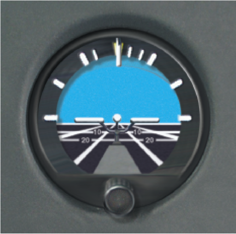
ATTITUDE INDICATOR
The attitude indicator provides a substitute for the natural horizon. It is the only instrument that provides an immediate and direct indication of the helicopter’s pitch and bank attitude. Since most attitude indicators
installed in helicopters are electrically powered, there may be a separate power switch, as well as a warning flag within the instrument, that indicates a loss of power. A caging or “quick erect” knob may be included, so you can stabilize the spin axis if the gyro has tumbled. [Figure 12-5]
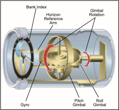
Figure 12-5. The gyro in the attitude indicator spins in the horizontal plane. Two mountings, or gimbals, are used so that both pitch and roll can be sensed simultaneously. Due to rigidity in space, the gyro remains in a fixed position relative to the horizon as the case and helicopter rotate around it.
HEADING INDICATOR
The heading indicator, which is sometimes referred to as a directional gyro (DG), senses movement around the vertical axis and provides a more accurate heading reference compared to a magnetic compass, which has a number of turning errors. [Figure 12-6].
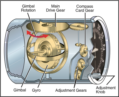
Figure 12-6. A heading indicator displays headings based on a 360° azimuth, with the final zero omitted. For example, a 6 represents 060°, while a 21 indicates 210°. The adjustment knob is used to align the heading indicator with the magnetic compass.
Due to internal friction within the gyroscope, precession is common in heading indicators. Precession causes the selected heading to drift from the set value.
Some heading indicators receive a magnetic north reference from a remote source and generally need no adjustment. Heading indicators that do not have this automatic north-seeking capability are often called
“free” gyros, and require that you periodically adjust them. You should align the heading indicator with the magnetic compass before flight and check it at 15-minute intervals during flight. When you do an in-flight alignment, be certain you are in straight-and-level, unaccelerated flight, with the magnetic compass showing a steady indication.
TURN INDICATORS
Turn indicators show the direction and the rate of turn.
A standard rate turn is 3° per second, and at this rate you will complete a 360° turn in two minutes. A half-standard rate turn is 1.5° per second. Two types of indicators are used to display this information. The turn-and-slip indicator uses a needle to indicate direction and turn rate. When the needle is aligned with the white markings, called the turn index, you are in a standard rate turn. A half-standard rate turn is indicated when the needle is halfway between the indexes.
The turn-and-slip indicator does not indicate roll rate.
The turn coordinator is similar to the turn-and-slip indicator, but the gyro is canted, which allows it to sense roll rate in addition to rate of turn. The turn coordinator uses a miniature aircraft to indicate direction, as well as the turn and roll rate. [Figure 12-7]
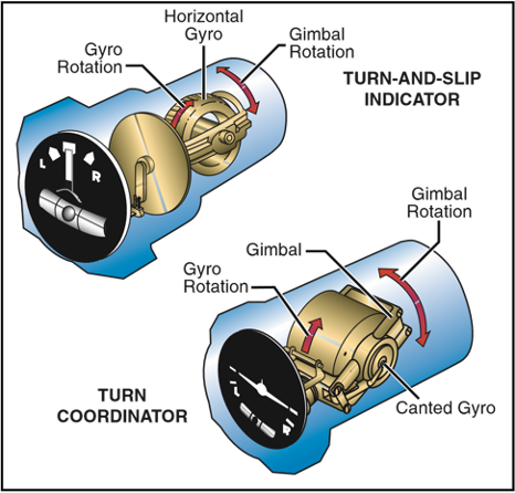
Figure 12-7. The gyros in both the turn-and-slip indicator and the turn coordinator are mounted so that they rotate in a vertical plane. The gimbal in the turn coordinator is set at an angle, or canted, which means precession allows the gyro to sense both rate of roll and rate of turn. The gimbal in the turn-and-slip indicator is horizontal. In this case, precession allows the gyro to sense only rate of turn. When the needle or miniature aircraft is aligned with the turn index, you are in a standard-rate turn.
Another part of both the turn coordinator and the turnand-slip indicator is the inclinometer. The position of the ball defines whether the turn is coordinated or not. The helicopter is either slipping or skidding anytime the ball is not centered, and usually requires an adjustment of the antitorque pedals or angle of bank to correct it. [Figure 12-8]
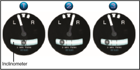
Figure 12-8. In a coordinated turn (instrument 1), the ball is centered. In a skid (instrument 2), the rate of turn is too great for the angle of bank, and the ball moves to the outside of the turn. Conversely, in a slip (instrument 3), the rate of turn is too small for the angle of bank, and the ball moves to the inside of the turn.
INSTRUMENT CHECK—During your preflight, check to see that the inclinometer is full of fluid and has no air bubbles. The ball should also be resting at its lowest point. Since almost all gyroscopic instruments installed in a helicopter are electrically driven, check to see that the power indicators are displaying off indications. Turn the master switch on and listen to the gyros spool up. There should be no abnormal sounds, such as a grinding sound, and the power out indicator flags should not be displayed. After engine start and before liftoff, set the direction indicator to the magnetic compass. During hover turns, check the heading indicator for proper operation and ensure that it has not precessed significantly. The turn indicator should also indicate a turn in the correct direction. During takeoff, check the attitude indicator for proper indication and recheck it during the first turn.
MAGNETIC COMPASS
In some helicopters, the magnetic compass is the only direction seeking instrument. Although the compass appears to move, it is actually mounted in such a way that the helicopter turns about the compass card as the card maintains its alignment with magnetic north.
COMPASS ERRORS
The magnetic compass can only give you reliable directional information if you understand its limitations and inherent errors. These include magnetic variation, compass deviation, and magnetic dip.
MAGNETIC VARIATION
When you fly under visual flight rules, you ordinarily navigate by referring to charts, which are oriented to true north. Because the aircraft compass is oriented to magnetic north, you must make allowances for the difference between these poles in order to navigate properly. You do this by applying a correction called variation to convert a true direction to a magnet direction. Variation at a given point is the angular difference between the true and magnetic poles. The amount of variation depends on where you are located on the earth’s surface. Isogonic lines connect points where the variation is equal, while the agonic line defines the points where the variation is zero. [Figure 12-9]
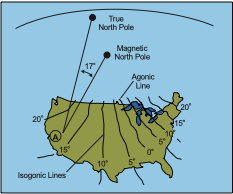
Figure 12-9. Variation at point A in the western United States is 17°. Since the magnetic north pole is located to the east of the true north pole in relation to this point, the variation is easterly. When the magnetic pole falls to the west of the true north pole, variation is westerly.
COMPASS DEVIATION
Besides the magnetic fields generated by the earth, other magnetic fields are produced by metal and electrical accessories within the helicopter. These magnetic fields distort the earth’s magnet force and cause the compass to swing away from the correct heading. Manufacturers often install compensating magnets within the compass housing to reduce the effects of deviation. These magnets are usually adjusted while the engine is running and all electrical equipment is operating. Deviation error, however, cannot be completely eliminated; therefore, a compass correction card is mounted near the compass.
The compass correction card corrects for deviation that occurs from one heading to the next as the lines of force interact at different angles.
MAGNETIC DIP
Magnetic dip is the result of the vertical component of the earth’s magnetic field. This dip is virtually nonexistent at the magnetic equator, since the lines of force are parallel to the earth’s surface and the vertical component is minimal. As you move a compass toward the poles, the vertical component increases, and magnetic dip becomes more apparent at these higher latitudes.
Magnetic dip is responsible for compass errors during acceleration, deceleration, and turns.
Acceleration and deceleration errors are fluctuations in the compass during changes in speed. In the northern hemisphere, the compass swings toward the north during acceleration and toward the south during decel-eration. When the speed stabilizes, the compass returns to an accurate indication. This error is most pronounced when you are flying on a heading of east or west, and decreases gradually as you fly closer to a north or south heading. The error does not occur when you are flying directly north or south. The memory aid, ANDS (Accelerate North, Decelerate South) may help you recall this error. In the southern hemisphere, this error occurs in the opposite direction.
Turning errors are most apparent when you are turning to or from a heading of north or south. This error increases as you near the poles as magnetic dip becomes more apparent. There is no turning error when flying near the magnetic equator. In the northern hemisphere, when you make a turn from a northerly heading, the compass gives an initial indication of a turn in the opposite direction. It then begins to show the turn in the proper direction, but lags behind the actual head-ing. The amount of lag decreases as the turn continues, then disappears as the helicopter reaches a heading of east or west. When you make a turn from a southerly heading, the compass gives an indication of a turn in the correct direction, but leads the actual heading. This error also disappears as the helicopter approaches an east or west heading.
INSTRUMENT CHECK-Prior to flight, make sure that the compass is full of fluid. During hover turns, the compass should swing freely and indicate known head-ings. Since that magnetic compass is required for all flight operations, the aircraft should never be flown with a faulty compass.
INSTRUMENT FLIGHT
To achieve smooth, positive control of the helicopter during instrument flight, you need to develop three fundamental skills. They are instrument cross-check, instrument interpretation, and aircraft control.
INSTRUMENT CROSS-CHECK
Cross-checking, sometimes referred to as scanning, is the continuous and logical observation of instruments for attitude and performance information. In attitude instrument flying, an attitude is maintained by reference to the instruments, which produces the desired result in performance. Due to human error, instrument error, and helicopter performance differences in various atmospheric and loading conditions, it is difficult to establish an attitude and have performance remain constant for a long period of time. These variables make it necessary for you to constantly check the instruments and make appropriate changes in the helicopter’s atti-tude. The actual technique may vary depending on what instruments are installed and where they are installed, as well as your experience and proficiency level. For this discussion, we will concentrate on the six basic flight instruments discussed earlier. [Figure 12-10]
At first, you may have a tendency to cross-check rapidly, looking directly at the instruments without knowing exactly what information you are seeking.
However, with familiarity and practice, the instrument cross-check reveals definite trends during specific flight conditions. These trends help you control the helicopter as it makes a transition from one flight condition to another.
If you apply your full concentration to a single instrument, you will encounter a problem called “fixation.” This results from a natural human inclination to observe a specific instrument carefully and accurately, often to the exclusion of other instruments. Fixation on a single instrument usually results in poor control. For example, while performing a turn, you may have a tendency to watch only the turn-and-slip indicator instead of including other instruments in your cross-check. This fixation on the turn-and-slip indicator often leads to a loss of altitude through poor pitch and bank control. You should look at each instrument only long enough to understand the information it presents, then continue on to the next one. Similarly, you may find yourself placing too much “emphasis” on a single instrument, instead of relying on a combination of instruments nec-essary for helicopter performance information. This differs from fixation in that you are using other instruments, but are giving too much attention to a particular one.
During performance of a maneuver, you may sometimes fail to anticipate significant instrument indications following attitude changes. For example, during leveloff from a climb or descent, you may concentrate on pitch control, while forgetting about heading or roll informa-tion. This error, called “omission,” results in erratic control of heading and bank.
In spite of these common errors, most pilots can adapt well to flight by instrument reference after instruction and practice. You may find that you can control the helicopter more easily and precisely by instruments.
INSTRUMENT INTERPRETATION
The flight instruments together give a picture of what is going on. No one instrument is more important than the next; however, during certain maneuvers or condi-tions, those instruments that provide the most pertinent and useful information are termed primary instruments.
Those which back up and supplement the primary instruments are termed supporting instruments. For example, since the attitude indicator is the only instrument that provides instant and direct aircraft attitude information, it should be considered primary during any change in pitch or bank attitude. After the new attitude is established, other instruments become primary, and the attitude indicator usually becomes the supporting instrument.
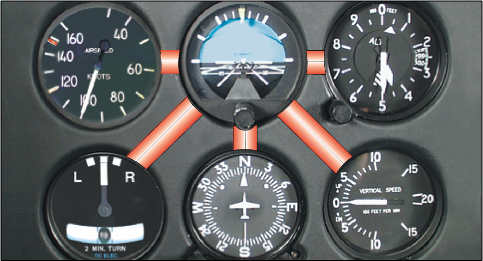
Figure 12-10. In most situations, the cross-check pattern includes the attitude indicator between the cross-check of each of the other instruments. A typical cross-check might progress as follows: attitude indicator, altimeter, attitude indicator, VSI, attitude indicator, heading indicator, attitude indicator, and so on.
AIRCRAFT CONTROL
Controlling the helicopter is the result of accurately interpreting the flight instruments and translating these readings into correct control responses. Aircraft control involves adjustment to pitch, bank, power, and trim in order to achieve a desired flight path.
Pitch attitude control is controlling the movement of the helicopter about its lateral axis. After interpreting the helicopter’s pitch attitude by reference to the pitch instruments (attitude indicator, altimeter, airspeed indi-cator, and vertical speed indicator), cyclic control adjustments are made to affect the desired pitch atti-tude. In this chapter, the pitch attitudes illustrated are approximate and will vary with different helicopters.
Bank attitude control is controlling the angle made by the lateral tilt of the rotor and the natural horizon, or, the movement of the helicopter about its longitudinal axis. After interpreting the helicopter’s bank instruments (attitude indicator, heading indicator, and turn indicator), cyclic control adjustments are made to attain the desired bank attitude.
Power control is the application of collective pitch with corresponding throttle control, where applicable. In straight-and-level flight, changes of collective pitch are made to correct for altitude deviations if the error is more than 100 feet, or the airspeed is off by more than 10 knots. If the error is less than that amount, use a slight cyclic climb or descent.
In order to fly a helicopter by reference to the instruments, you should know the approximate power settings required for your particular helicopter in various load configurations and flight conditions.
Trim, in helicopters, refers to the use of the cyclic centering button, if the helicopter is so equipped, to relieve all possible cyclic pressures. Trim also refers to the use of pedal adjustment to center the ball of the turn indicator.
Pedal trim is required during all power changes.
The proper adjustment of collective pitch and cyclic friction helps you relax during instrument flight.
Friction should be adjusted to minimize overcontrol-ling and to prevent creeping, but not applied to such a degree that control movement is limited. In addition, many helicopters equipped for instrument flight contain stability augmentation systems or an autopilot to help relieve pilot workload.
STRAIGHT-AND-LEVEL FLIGHT
Straight-and-level unaccelerated flight consists of maintaining the desired altitude, heading, airspeed, and pedal trim.
PITCH CONTROL
The pitch attitude of a helicopter is the angular relation of its longitudinal axis and the natural horizon. If avail-able, the attitude indicator is used to establish the desired pitch attitude. In level flight, pitch attitude varies with airspeed and center of gravity. At a constant altitude and a stabilized airspeed, the pitch attitude is approximately level. [Figure 12-11]
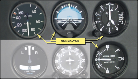
Figure 12-11. The flight instruments for pitch control are the airspeed indicator, attitude indicator, altimeter, and vertical speed indicator.
ATTITUDE INDICATOR
The attitude indicator gives a direct indication of the pitch attitude of the helicopter. In visual flight, you attain the desired pitch attitude by using the cyclic to raise and lower the nose of the helicopter in relation to the natural horizon. During instrument flight, you follow exactly the same procedure in raising or lowering the miniature aircraft in relation to the horizon bar.
You may note some delay between control application and resultant instrument change. This is the normal control lag in the helicopter and should not be confused with instrument lag. The attitude indicator may show small misrepresentations of pitch attitude during maneuvers involving acceleration, deceleration, or turns. This precession error can be detected quickly by cross-checking the other pitch instruments.
If the miniature aircraft is properly adjusted on the ground, it may not require readjustment in flight. If the miniature aircraft is not on the horizon bar after level-off at normal cruising airspeed, adjust it as necessary while maintaining level flight with the other pitch instruments. Once the miniature aircraft has been adjusted in level flight at normal cruising airspeed, leave it unchanged so it will give an accurate picture of pitch attitude at all times.
When making initial pitch attitude corrections to maintain altitude, the changes of attitude should be small and smoothly applied. The initial movement of the horizon bar should not exceed one bar width high or low. [Figure 12-12] If a further change is required, an additional correction of one-half bar normally corrects any deviation from the desired altitude. This one and
one-half bar correction is normally the maximum pitch attitude correction from level flight attitude. After you have made the correction, cross-check the other pitch instruments to determine whether the pitch attitude change is sufficient. If more correction is needed to return to altitude, or if the airspeed varies more than 10 knots from that desired, adjust the power.
ALTIMETER
The altimeter gives an indirect indication of the pitch attitude of the helicopter in straight-and-level flight.
Since the altitude should remain constant in level flight, deviation from the desired altitude shows a need for a change in pitch attitude, and if necessary, power.
When losing altitude, raise the pitch attitude and, if necessary, add power. When gaining altitude, lower the pitch attitude and, if necessary, reduce power.
The rate at which the altimeter moves helps in determining pitch attitude. A very slow movement of the altimeter indicates a small deviation from the desired pitch attitude, while a fast movement of the altimeter indicates a large deviation from the desired pitch atti-tude. Make any corrective action promptly, with small control changes. Also, remember that movement of the altimeter should always be corrected by two distinct changes. The first is a change of attitude to stop the altimeter; and the second, a change of attitude to return smoothly to the desired altitude. If the altitude and airspeed are more than 100 feet and 10 knots low, respectively, apply power along with an increase of pitch attitude. If the altitude and airspeed are high by more than 100 feet and 10 knots, reduce power and lower the pitch attitude.
There is a small lag in the movement of the altimeter; however, for all practical purposes, consider that the altimeter gives an immediate indication of a change, or a need for change in pitch attitude.
Since the altimeter provides the most pertinent information regarding pitch in level flight, it is considered primary for pitch.
VERTICAL SPEED INDICATOR
The vertical speed indicator gives an indirect indication of the pitch attitude of the helicopter and should be used in conjunction with the other pitch instruments to attain a high degree of accuracy and precision. The instrument indicates zero when in level flight. Any movement of the needle from the zero position shows a need for an immediate change in pitch attitude to return it to zero.
Always use the vertical speed indicator in conjunction with the altimeter in level flight. If a movement of the vertical speed indicator is detected, immediately use the proper corrective measures to return it to zero. If the correction is made promptly, there is usually little or no change in altitude. If you do not zero the needle of the vertical speed indicator immediately, the results will show on the altimeter as a gain or loss of altitude.
The initial movement of the vertical speed needle is instantaneous and indicates the trend of the vertical movement of the helicopter. It must be realized that a period of time is necessary for the vertical speed indicator to reach its maximum point of deflection after a correction has been made. This time element is commonly referred to as “lag.” The lag is directly proportional to the speed and magnitude of the pitch change. If you employ smooth control techniques and make small adjustments in pitch attitude, lag is minimized, and the vertical speed indicator is easy to interpret. Overcontrolling can be minimized by first neutralizing the controls and allowing the pitch attitude to stabilize; then readjusting the pitch attitude by noting the indications of the other pitch instruments.
Occasionally, the vertical speed indicator may be slightly out of calibration. This could result in the instrument indicating a slight climb or descent even when the helicopter is in level flight. If it cannot be readjusted properly, this error must be taken into consideration when using the vertical speed indicator for pitch control. For example, if the vertical speed indicator showed a descent of 100 f.p.m. when the helicopter was in level flight, you would have to use that indication as level flight. Any deviation from that reading would indicate a change in attitude.
AIRSPEED INDICATOR
The airspeed indicator gives an indirect indication of helicopter pitch attitude. With a given power setting and pitch attitude, the airspeed remains constant. If the airspeed increases, the nose is too low and should be raised. If the airspeed decreases, the nose is too high and should be lowered. A rapid change in airspeed indicates a large change in pitch attitude, and a slow change in airspeed indicates a small change in pitch attitude.
There is very little lag in the indications of the airspeed indicator. If, while making attitude changes, you notice some lag between control application and change of airspeed, it is most likely due to cyclic control lag.
Generally, a departure from the desired airspeed, due to an inadvertent pitch attitude change, also results in a change in altitude. For example, an increase in airspeed due to a low pitch attitude results in a decrease in alti-tude. A correction in the pitch attitude regains both airspeed and altitude.
BANK CONTROL
The bank attitude of a helicopter is the angular relation of its lateral axis and the natural horizon. To maintain a straight course in visual flight, you must keep the lateral axis of the helicopter level with the natural hori-zon. Assuming the helicopter is in coordinated flight, any deviation from a laterally level attitude produces a turn. Figure 12-13]
ATTITUDE INDICATOR
The attitude indicator gives a direct indication of the bank attitude of the helicopter. For instrument flight,
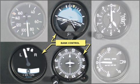
Figure 12-13. The flight instruments used for bank control are the attitude, heading, and turn indicators.
the miniature aircraft and the horizon bar of the attitude indicator are substituted for the actual helicopter and the natural horizon. Any change in bank attitude of the helicopter is indicated instantly by the miniature air-craft. For proper interpretations of this instrument, you should imagine being in the miniature aircraft. If the helicopter is properly trimmed and the rotor tilts, a turn begins. The turn can be stopped by leveling the miniature aircraft with the horizon bar. The ball in the turn-and-slip indicator should always be kept centered through proper pedal trim.
The angle of bank is indicated by the pointer on the banking scale at the top of the instrument. [Figure 12- 14] Small bank angles, which may not be seen by observing the miniature aircraft, can easily be determined by referring to the banking scale pointer.
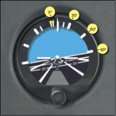
Figure 12-14. The banking scale at the top of the attitude indicator indicates varying degrees of bank. In this example, the helicopter is banked a little over 10° to the right.
Pitch and bank attitudes can be determined simultaneously on the attitude indicator. Even though the miniature aircraft is not level with the horizon bar, pitch attitude can be established by observing the relative position of the miniature aircraft and the horizon bar.
The attitude indicator may show small misrepresentations of bank attitude during maneuvers that involve turns. This precession error can be immediately detected by closely cross-checking the other bank instruments during these maneuvers. Precession normally is noticed when rolling out of a turn. If, on the completion of a turn, the miniature aircraft is level and
the helicopter is still turning, make a small change of bank attitude to center the turn needle and stop the movement of the heading indicator.
HEADING INDICATOR
In coordinated flight, the heading indicator gives an indirect indication of the helicopter’s bank attitude.
When a helicopter is banked, it turns. When the lateral axis of the helicopter is level, it flies straight.
Therefore, in coordinated flight, when the heading indicator shows a constant heading, the helicopter is level laterally. A deviation from the desired heading indicates a bank in the direction the helicopter is turning.
A small angle of bank is indicated by a slow change of heading; a large angle of bank is indicated by a rapid change of heading. If a turn is noticed, apply opposite cyclic until the heading indicator indicates the desired heading, simultaneously checking that the ball is cen-tered. When making the correction to the desired head-ing, you should not use a bank angle greater than that required to achieve a standard rate turn. In addition, if the number of degrees of change is small, limit the bank angle to the number of degrees to be turned. Bank angles greater than these require more skill and precision in attaining the desired results. During straight-and-level flight, the heading indicator is the primary reference for bank control.
TURN INDICATOR
During coordinated flight, the needle of the turn-and-slip indicator gives an indirect indication of the bank attitude of the helicopter. When the needle is displaced from the vertical position, the helicopter is turning in the direction of the displacement. Thus, if the needle is displaced to the left, the helicopter is turning left. Bringing the needle back to the vertical position with the cyclic produces straight flight. A close observation of the needle is necessary to accurately interpret small deviations from the desired position.
Cross-check the ball of the turn-and-slip indicator to determine that the helicopter is in coordinated flight. If the rotor is laterally level and torque is properly compensated for by pedal pressure, the ball remains in the center. To center the ball, level the helicopter laterally by reference to the other bank instruments, then center the ball with pedal trim. Torque correction pressures vary as you make power changes. Always check the ball following such changes.
COMMON ERRORS DURING STRAIGHT-AND-LEVEL FLIGHT
- Failure to maintain altitude.
- Failure to maintain heading.
- Overcontrolling pitch and bank during corrections.
- Failure to maintain proper pedal trim.
- Failure to cross-check all available instruments.
POWER CONTROL DURING STRAIGHT-AND-LEVEL FLIGHT
Establishing specific power settings is accomplished through collective pitch adjustments and throttle control, where necessary. For reciprocating powered helicopters, power indications are observed on the manifold pressure gauge. For turbine powered helicop-ters, power is observed on the torque gauge. (Since most IFR certified helicopters are turbine powered, this discussion concentrates on this type of helicopter.)
At any given airspeed, a specific power setting determines whether the helicopter is in level flight, in a climb, or in a descent. For example, cruising airspeed maintained with cruising power results in level flight.
If you increase the power setting and hold the airspeed constant, the helicopter climbs. Conversely, if you decrease power and hold the airspeed constant, the helicopter descends. As a rule of thumb, in a turbine-engine powered helicopter, a 10 to 15 percent change in the torque value required to maintain level flight results in a climb or descent of approximately 500 f.p.m., if the airspeed remains the same.
If the altitude is held constant, power determines the airspeed. For example, at a constant altitude, cruising power results in cruising airspeed. Any deviation from the cruising power setting results in a change of air-speed. When power is added to increase airspeed, the nose of the helicopter pitches up and yaws to the right in a helicopter with a counterclockwise main rotor blade rotation. When power is reduced to decrease air-speed, the nose pitches down and yaws to the left. The yawing effect is most pronounced in single-rotor helicop-ters, and is absent in helicopters with counter-rotating rotors. To counteract the yawing tendency of the helicop-ter, apply pedal trim during power changes.
To maintain a constant altitude and airspeed in level flight, coordinate pitch attitude and power control. The relationship between altitude and airspeed determines the need for a change in power and/or pitch attitude. If the altitude is constant and the airspeed is high or low, change the power to obtain the desired airspeed.
During the change in power, make an accurate interpretation of the altimeter; then counteract any deviation from the desired altitude by an appropriate change of pitch attitude. If the altitude is low and the airspeed is high, or vice versa, a change in pitch attitude alone may return the helicopter to the proper altitude and air-speed. If both airspeed and altitude are low, or if both are high, a change in both power and pitch attitude is necessary.
To make power control easy when changing airspeed, it is necessary to know the approximate power settings for the various airspeeds that will be flown. When the air-speed is to be changed any appreciable amount, adjust the torque so that it is approximately five percent over or under that setting necessary to maintain the new airspeed.
As the power approaches the desired setting, include the torque meter in the cross-check to determine when the proper adjustment has been accomplished. As the airspeed is changing, adjust the pitch attitude to maintain a constant altitude. A constant heading should be maintained throughout the change. As the desired airspeed is approached, adjust power to the new cruising power setting and further adjust pitch attitude to maintain altitude.
Overpowering and underpowering torque approximately five percent results in a change of airspeed at a moderate rate, which allows ample time to adjust pitch and bank smoothly. The instrument indications for straight-and-level flight at normal cruise, and during the transition from normal cruise to slow cruise are illustrated in figures 12-15 and 12-16 on the next page. After the airspeed has stabilized at slow cruise, the attitude indicator shows an approximate level pitch attitude.
The altimeter is the primary pitch instrument during level flight, whether flying at a constant airspeed, or during a change in airspeed. Altitude should not change during airspeed transitions. The heading indicator remains the primary bank instrument. Whenever the airspeed is changed any appreciable amount, the torque meter is momentarily the primary instrument for power control. When the airspeed approaches that desired, the airspeed indicator again becomes the primary instrument for power control.
The cross-check of the pitch and bank instruments to produce straight-and-level flight should be combined with the power control instruments. With a constant power setting, a normal cross-check should be satisfactory. When changing power, the speed of the cross-check must be increased to cover the pitch and bank instruments adequately. This is necessary to counteract any deviations immediately.
COMMON ERRORS DURING AIRSPEED CHANGES
- Improper use of power.
- Overcontrolling pitch attitude.
- Failure to maintain heading.
- Failure to maintain altitude.
- Improper pedal trim.
STRAIGHT CLIMBS (CONSTANT AIRSPEED AND CONSTANT RATE)
For any power setting and load condition, there is only one airspeed that will give the most efficient rate of climb. To determine this, you should consult the climb data for the type of helicopter being flown. The technique varies according to the airspeed on entry and whether you want to make a constant airspeed or constant rate climb.
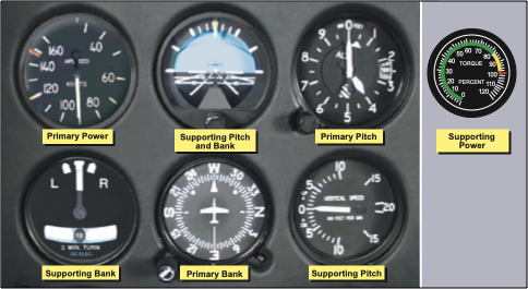
Figure 12-15. Flight instrument indications in straight-and-level flight at normal cruise speed.
To enter a constant airspeed climb from cruise airspeed, when the climb speed is lower than cruise speed, simultaneously increase power to the climb power setting and adjust pitch attitude to the approximate climb atti-tude. The increase in power causes the helicopter to start climbing and only very slight back cyclic pressure is needed to complete the change from level to climb attitude. The attitude indicator should be used to accomplish the pitch change. If the transition from level flight to a climb is smooth, the vertical speed indicator shows an immediate upward trend and then stops at a rate appropriate to the stabilized airspeed and atti-tude. Primary and supporting instruments for climb entry are illustrated in figure 12-17.
When the helicopter stabilizes on a constant airspeed and attitude, the airspeed indicator becomes primary
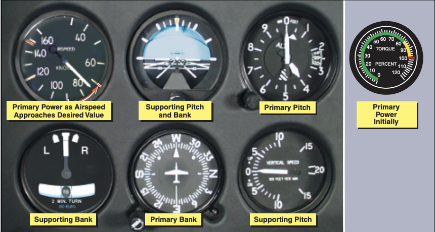
Figure 12-16. Flight instrument indications in straight-and-level flight with airspeed decreasing.

for pitch. The torque meter continues to be primary for power and should be monitored closely to determine 1f the proper climb power setting is being maintained.
Primary and supporting instruments for a stabilized constant airspeed climb are shown in figure 12-18.
The technique and procedures for entering a constant rate climb are very similar to those previously described for a constant airspeed climb. For training purposes, a constant rate climb is entered from climb airspeed. The rate used is the one that is appropriate for

Figure 12-18. Flight instrument indications in a stabilized, constant airspeed climb.
the particular helicopter being flown. Normally, in helicopters with low climb rates, 500 f.p.m. is appropriate, in helicopters capable of high climb rates, use a rate of 1,000 f.p.m.
To enter a constant rate climb, increase power to the approximate setting for the desired rate. As power is applied, the airspeed indicator is primary for pitch until the vertical speed approaches the desired rate. At this time, the vertical speed indicator becomes primary for pitch. Change pitch attitude by reference to the attitude indicator to maintain the desired vertical speed. When the VSI becomes primary for pitch, the airspeed indicator becomes primary for power. Primary and supporting instruments for a stabilized constant rate climb are illustrated in figure 12-19. Adjust power to maintain desired airspeed. Pitch attitude and power corrections should be closely coordinated. To illustrate this, if the vertical speed is correct but the airspeed is low, add power. As power is increased, it may be necessary to lower the pitch attitude slightly to avoid increasing the vertical rate. Adjust the pitch attitude smoothly to avoid over-controlling. Small power corrections usually will be sufficient to bring the airspeed back to the desired indi-cation.
LEVELOFF
The leveloff from a constant airspeed climb must be started before reaching the desired altitude. Although the amount of lead varies with the helicopter being flown and your piloting technique, the most important factor is vertical speed. As a rule of thumb, use 10 percent of the vertical velocity as your lead point. For example, if the rate of climb is 500 f.p.m., initiate the leveloff approximately 50 feet before the desired altitude. When the proper lead altitude is reached, the altimeter becomes primary for pitch. Adjust the pitch attitude to the level flight attitude for that airspeed. Cross-check the altimeter and VSI to determine when level flight has been attained at the desired altitude. To level off at cruise air-speed, if this speed is higher than climb airspeed, leave the power at the climb power setting until the airspeed approaches cruise airspeed, then reduce it to the cruise power setting.
The leveloff from a constant rate climb is accomplished in the same manner as the leveloff from a constant airspeed climb.
STRAIGHT DESCENTS (CONSTANT AIRSPEED AND CONSTANT RATE)
A descent may be performed at any normal airspeed the helicopter is capable of, but the airspeed must be determined prior to entry. The technique is determined by whether you want to perform a constant airspeed or a constant rate descent.
ENTRY
If your airspeed is higher than descending airspeed, and you wish to make a constant airspeed descent at the descending airspeed, reduce power to the descending power setting and maintain a constant altitude using cyclic pitch control. When you approach the descending airspeed, the airspeed indicator becomes primary for pitch, and the torque meter is primary for power. As you hold the airspeed constant, the helicopter begins to descend. For a constant rate descent, reduce the power

Figure 12-19. Flight instrument indications in a stabilized constant rate climb.
to the approximate setting for the desired rate. If the descent is started at the descending airspeed, the airspeed indicator is primary for pitch until the VSI approaches the desired rate. At this time, the vertical speed indicator becomes primary for pitch, and the airspeed indicator becomes primary for power.
Coordinate power and pitch attitude control as was described earlier for constant rate climbs.
LEVELOFF
The leveloff from a constant airspeed descent may be made at descending airspeed or at cruise airspeed, if this is higher than descending airspeed. As in a climb leveloff, the amount of lead depends on the rate of descent and control technique. For a leveloff at descending airspeed, the lead should be approximately 10 percent of the vertical speed. At the lead altitude, simultaneously increase power to the setting necessary to maintain descending airspeed in level flight. At this point, the altimeter becomes primary for pitch, and the airspeed indicator becomes primary for power.
To level off at a higher airspeed than descending air-speed, increase the power approximately 100 to 150 feet prior to reaching the desired altitude. The power setting should be that which is necessary to maintain the desired airspeed in level flight. Hold the vertical speed constant until approximately 50 feet above the desired altitude. At this point, the altimeter becomes primary for pitch, and the airspeed indicator becomes primary for power. The leveloff from a constant rate descent should be accomplished in the same manner as the lev-eloff from a constant airspeed descent.
COMMON ERRORS DURING STRAIGHT CLIMBS AND DESCENTS
- Failure to maintain heading.
- Improper use of power.
- Poor control of pitch attitude.
- Failure to maintain proper pedal trim.
- Failure to level off on desired altitude.
TURNS
When making turns by reference to the flight instru-ments, they should be made at a definite rate. Turns described in this chapter are those that do not exceed a standard rate of 3° per second as indicated on the turn-and-slip indicator. True airspeed determines the angle of bank necessary to maintain a standard rate turn. A rule of thumb to determine the approximate angle of bank required for a standard rate turn is to divide your airspeed by 10 and add one-half the result. For exam-ple, at 60 knots, approximately 9° of bank is required (60 ÷ 10 = 6 + 3 = 9); at 80 knots, approximately 12° of bank is needed for a standard rate turn.
To enter a turn, apply lateral cyclic in the direction of the desired turn. The entry should be accomplished smoothly, using the attitude indicator to establish the approximate bank angle. When the turn indicator indicates a standard rate turn, it becomes primary for bank.
The attitude indicator now becomes a supporting instru-ment. During level turns, the altimeter is primary for pitch, and the airspeed indicator is primary for power.
Primary and supporting instruments for a stabilized standard rate turn are illustrated in figure 12-20. If an

Figure 12-20. Flight instrument indications for a standard rate turn to the left.
increase in power is required to maintain airspeed, slight forward cyclic pressure may be required since the helicopter tends to pitch up as collective pitch angle is increased. Apply pedal trim, as required, to keep the ball centered.
To recover to straight-and-level flight, apply cyclic in the direction opposite the turn. The rate of roll-out should be the same as the rate used when rolling into the turn. As you initiate the turn recover, the attitude indicator becomes primary for bank. When the helicopter is approximately level, the heading indicator becomes primary for bank as in straight-and-level flight. Cross-check the airspeed indicator and ball closely to maintain the desired airspeed and pedal trim.
TURNS TO A PREDETERMINED HEADING
A helicopter turns as long as its lateral axis is tilted; there-fore, the recovery must start before the desired heading is reached. The amount of lead varies with the rate of turn and your piloting technique.
As a guide, when making a 3° per second rate of turn, use a lead of one-half the bank angle. For example, if you are using a 12° bank angle, use half of that, or 6°, as the lead point prior to your desired heading. Use this lead until you are able to determine the exact amount required by your particular technique. The bank angle should never exceed the number of degrees to be turned. As in any standard rate turn, the rate of recovery should be the same as the rate for entry. During turns to predetermined headings, cross-check the primary and supporting pitch, bank, and power instruments closely.
TIMED TURNS
A timed turn is a turn in which the clock and turn-and-slip indicator are used to change heading a definite number of degrees in a given time. For example, using a standard rate turn, a helicopter turns 45° in 15 sec-onds. Using a half-standard rate turn, the helicopter turns 45° in 30 seconds. Timed turns can be used if your heading indicator becomes inoperative.
Prior to performing timed turns, the turn coordinator should be calibrated to determine the accuracy of its indications. To do this, establish a standard rate turn by referring to the turn-and-slip indicator. Then as the sweep second hand of the clock passes a cardinal point (12, 3, 6, or 9), check the heading on the heading indi-cator. While holding the indicated rate of turn constant, note the heading changes at 10-second intervals. If the helicopter turns more or less than 30° in that interval, a smaller or larger deflection of the needle is necessary to produce a standard rate turn. When you have calibrated the turn-and-slip indicator during turns in each direction, note the corrected deflections, if any, and apply them during all timed turns.
You use the same cross-check and control technique in making timed turns that you use to make turns to a predetermined heading, except that you substitute the clock for the heading indicator. The needle of the turn-and-slip indicator is primary for bank control, the altimeter is primary for pitch control, and the airspeed indicator is primary for power control. Begin the roll-in when the clock’s second hand passes a cardinal point, hold the turn at the calibrated standard-rate indication, or half-standard-rate for small changes in heading, and begin the roll-out when the computed number of seconds has elapsed. If the roll-in and roll-out rates are the same, the time taken during entry and recovery need not be considered in the time computation.
If you practice timed turns with a full instrument panel, check the heading indicator for the accuracy of your turns. If you execute the turns without the heading indi-cator, use the magnetic compass at the completion of the turn to check turn accuracy, taking compass deviation errors into consideration.
CHANGE OF AIRSPEED IN TURNS
Changing airspeed in turns is an effective maneuver for increasing your proficiency in all three basic instrument skills. Since the maneuver involves simultaneous changes in all components of control, proper execution requires a rapid cross-check and interpretation, as well as smooth control. Proficiency in the maneuver also contributes to your confidence in the instruments during attitude and power changes involved in more complex maneuvers.
Pitch and power control techniques are the same as those used during airspeed changes in straight-and-level flight. As discussed previously, the angle of bank necessary for a given rate of turn is proportional to the true airspeed. Since the turns are executed at standard rate, the angle of bank must be varied in direct proportion to the airspeed change in order to maintain a constant rate of turn. During a reduction of airspeed, you must decrease the angle of bank and increase the pitch attitude to maintain altitude and a standard rate turn.
The altimeter and the needle on the turn indicator should remain constant throughout the turn. The altimeter is primary for pitch control, and the turn needle is primary for bank control. The torque meter is primary for power control while the airspeed is chang-ing. As the airspeed approaches the new indication, the airspeed indicator becomes primary for power control.
Two methods of changing airspeed in turns may be used. In the first method, airspeed is changed after the turn is established. In the second method, the airspeed change is initiated simultaneously with the turn entry.
The first method is easier, but regardless of the method used, the rate of cross-check must be increased as you reduce power. As the helicopter decelerates, check the altimeter and VSI for needed pitch changes, and the bank instruments for needed bank changes. If the needle of the turn-and-slip indicator shows a deviation from the desired deflection, change the bank. Adjust pitch attitude to maintain altitude. When the airspeed approaches that desired, the airspeed indicator becomes primary for power control. Adjust the torque meter to maintain the desired airspeed. Use pedal trim to ensure the maneuver is coordinated.
Until your control technique is very smooth, frequently cross-check the attitude indicator to keep from over-controlling and to provide approximate bank angles appropriate for the changing airspeeds.
30° BANK TURN
A turn using 30° of bank is seldom necessary, or advis-able, in IMC, but it is an excellent maneuver to increase your ability to react quickly and smoothly to rapid changes of attitude. Even though the entry and recovery technique are the same as for any other turn, you will probably find it more difficult to control pitch because of the decrease in vertical lift as the bank increases. Also, because of the decrease in vertical lift, there is a tendency to lose altitude and/or airspeed.
Therefore, to maintain a constant altitude and airspeed, additional power is required. You should not initiate a correction, however, until the instruments indicate the need for a correction. During the maneuver, note the need for a correction on the altimeter and vertical speed indicator, then check the indications on the attitudeindicator, and make the necessary adjustments. After you have made this change, again check the altimeter and vertical speed indicator to determine whether or not the correction was adequate.
CLIMBING AND DESCENDING TURNS
For climbing and descending turns, the techniques described earlier for straight climbs and descents and those for standard rate turns are combined. For practice, start the climb or descent and turn simultaneously. The primary and supporting instruments for a stabilized constant airspeed left climbing turn are illustrated in figure
12-21. The leveloff from a climbing or descending turn is the same as the leveloff from a straight climb or descent. To recover to straight-and-level flight, you may stop the turn and then level off, level off and then stop the turn, or simultaneously level off and stop the turn.
During climbing and descending turns, keep the ball of the turn indicator centered with pedal trim.
COMPASS TURNS
The use of gyroscopic heading indicators make heading control very easy. However, if the heading indicator fails or your helicopter does not have one installed, you must use the magnetic compass for heading refer-ence. When making compass-only turns, you need to adjust for the lead or lag created by acceleration and deceleration errors so that you roll out on the desired heading. When turning to a heading of north, the lead for the roll-out must include the number of degrees of your latitude plus the lead you normally use in recovery from turns. During a turn to a south heading, maintain the turn until the compass passes south the number of degrees of your latitude, minus your normal roll-out lead. For example, when turning from an easterly direction to north, where the latitude is 30°, start the roll-out when the compass reads 037° (30° plus one-half the 15° angle of bank, or whatever amount is appropriate for your rate of roll-out). When turning from an easterly direction to south, start the roll-out when the magnetic compass reads 203° (180° plus 30° minus one-half the angle of bank). When making similar turns from a westerly direction, the appropriate points at which to begin your roll-out would be 323° for a turn to north, and 157° for a turn to south.

Figure 12-21. Flight instrument indications for a stabilized left climbing turn at a constant airspeed.
COMMON ERRORS DURING TURNS
- Failure to maintain desired turn rate.
- Failure to maintain altitude in level turns.
- Failure to maintain desired airspeed.
- Variation in the rate of entry and recovery.
- Failure to use proper lead in turns to a heading.
- Failure to properly compute time during timed turns.
- Failure to use proper leads and lags during the compass turns.
- Improper use of power.
- Failure to use proper pedal trim.
UNUSUAL ATTITUDES
Any maneuver not required for normal helicopter instrument flight is an unusual attitude and may be caused by any one or a combination of factors, such as turbulence, disorientation, instrument failure, confusion, preoccupation with cockpit duties, carelessness in cross-checking, errors in instrument interpretation, or lack of proficiency in aircraft control. Due to the instability characteristics of the helicopter, unusual attitudes can be extremely crit-ical. As soon as you detect an unusual attitude, make a recovery to straight-and-level flight as soon as possible with a minimum loss of altitude.
To recover from an unusual attitude, correct bank and pitch attitude, and adjust power as necessary. All components are changed almost simultaneously, with little lead of one over the other. You must be able to perform this task with and without the attitude indicator. If the helicopter is in a climbing or descending turn, correct bank, pitch, and power. The bank attitude should be corrected by referring to the turn-and-slip indicator and attitude indicator. Pitch attitude should be corrected by reference to the altimeter, airspeed indicator, VSI, and attitude indicator. Adjust power by referring to the airspeed indicator and torque meter.
Since the displacement of the controls used in recoveries from unusual attitudes may be greater than those for normal flight, take care in making adjustments as straight-and-level flight is approached. Cross-check the other instruments closely to avoid overcontrolling.
COMMON ERRORS DURING UNUSUAL ATTITUDE RECOVERIES
- Failure to make proper pitch correction.
- Failure to make proper bank correction.
- Failure to make proper power correction.
- Overcontrol of pitch and/or bank attitude.
- Overcontrol of power.
- Excessive loss of altitude.
EMERGENCIES
Emergencies under instrument flight are handled similarly to those occurring during VFR flight. A thorough knowledge of the helicopter and its systems, as well as good aeronautical knowledge and judgment, prepares you to better handle emergency situations. Safe operations begin with preflight planning and a thorough pre-flight. Plan your route of flight so that there are adequate landing sites in the event you have to make an emergency landing. Make sure you have all your resources, such as maps, publications, flashlights, and fire extinguishers readily available for use in an emergency.
During any emergency, you should first fly the aircraft.
This means that you should make sure the helicopter is under control, including the determination of emergency landing sites. Then perform the emergency checklist memory items, followed by written items in the RFM.
Once all these items are under control, you should notify ATC. Declare any emergency on the last assigned ATC frequency, or if one was not issued, transmit on the emergency frequency 121.5. Set the transponder to the emergency squawk code 7700. This code triggers an alarm or a special indicator in radar facilities.
Most in-flight emergencies, including low fuel and a complete electrical failure, require you to land as soon as possible. In the event of an electrical fire, turn all nonessential equipment off and land immediately. Some essential electrical instruments, such as the attitude indi-cator, may be required for a safe landing. A navigation radio failure may not require an immediate landing as long as the flight can continue safely. In this case, you should land as soon as practical. ATC may be able to provide vectors to a safe landing area. For the specific details on what to do during an emergency, you should refer to the RFM for the helicopter you are flying.
Land as soon as possible-Land without delay at the nearest suitable area, such as an open field, at which a safe approach and landing is assured.
Land immediately-The urgency of the landing is paramount. The primary consideration is to assure the survival of the occupants. Landing in trees, water, or other unsafe areas should be considered only as a last resort.
Land as soon as practical-The landing site and duration of flight are at the discretion of the pilot. Extended flight beyond the nearest approved landing area is not recommended.
AUTOROTATIONS
Both straight-ahead and turning autorotations should be practiced by reference to instruments. This training will ensure that you can take prompt corrective action to maintain positive aircraft control in the event of an engine failure.
To enter autorotation, reduce collective pitch smoothly to maintain a safe rotor r.p.m. and apply pedal trim to keep the ball of the turn-and-slip indicator centered.
The pitch attitude of the helicopter should be approximately level as shown by the attitude indicator. The airspeed indicator is the primary pitch instrument and should be adjusted to the recommended autorotation speed. The heading indicator is primary for bank in a straight-ahead autorotation. In a turning autorotation, a standard rate turn should be maintained by reference to the needle of the turn-and-slip indicator.
COMMON ERRORS DURING AUTOROTATIONS
- Uncoordinated entry due to improper pedal trim.
- Poor airspeed control due to improper pitch attitude.
- Poor heading control in straight-ahead autorotations.
- Failure to maintain proper rotor r.p.m.
- Failure to maintain a standard rate turn during turning autorotations.
SERVO FAILURE
Most helicopters certified for single-pilot IFR flight are required to have autopilots, which greatly reduces pilot workload. If an autopilot servo fails, however, you have to resume manual control of the helicopter. How much your workload increases, depends on which servo fails. If a cyclic servo fails, you may want to land immediately as the workload increases tremendously.
If an antitorque or collective servo fails, you might be able to continue to the next suitable landing site.
INSTRUMENT TAKEOFF
This maneuver should only be performed as part of your training for an instrument rating. The procedures and techniques described here should be modified, as necessary, to conform with those set forth in the operating instructions for the particular helicopter being flown.
Adjust the miniature aircraft in the attitude indicator, as appropriate, for the aircraft being flown. After the helicopter is aligned with the runway or takeoff pad, to prevent forward movement of a helicopter equipped with a wheel-type landing gear, set the parking brake or apply the toe brakes. If the parking brake is used, it must be unlocked after the takeoff has been completed.
Apply sufficient friction to the collective pitch control to minimize overcontrolling and to prevent creeping.
Excessive friction should be avoided since this limits collective pitch movement.
After checking all instruments for proper indications, start the takeoff by applying collective pitch and a predetermined power setting. Add power smoothly and steadily to gain airspeed and altitude simultaneously and to prevent settling to the ground. As power is applied and the helicopter becomes airborne, use the antitorque pedals initially to maintain the desired heading. At the same time, apply forward cyclic to begin accelerating to climbing airspeed. During the initial acceleration, the pitch attitude of the helicopter, as read on the attitude indicator, should be one to two bar widths low. The primary and supporting instruments after becoming airborne are illustrated in figure 12-22. As the airspeed increases

Figure 12-22. Flight instrument indications during an instrument takeoff.
to the appropriate climb airspeed, adjust pitch gradually to climb attitude. As climb airspeed is reached, reduce power to the climb power setting and transition to a fully coordinated straight climb.
During the initial climbout, minor heading corrections should be made with pedals only until sufficient airspeed is attained to transition to fully coordinated flight. Throughout the instrument take-off, instrument cross-check and interpretations must
be rapid and accurate, and aircraft control positive and smooth.
COMMON ERRORS DURING INSTRUMENT
TAKEOFFS
- Failure to maintain heading.
- Overcontrolling pedals.
- Failure to use required power.
Failure to adjust pitch attitude as climbing airspeed is reached.


