Due to rudimentary flight control systems, early gyroplanes suffered from limited maneuverability. As technology improved, greater control of the rotor system and more effective control surfaces were developed. The modern gyroplane, while continuing to maintain an element of simplicity, now enjoys a high degree of maneuver- ability as a result of these improvements.
Cyclic control
The cyclic control provides the means whereby you are able to tilt the rotor system to provide the desired results. Tilting the rotor system provides all control for climbing, descending, and banking the gyroplane. The most common method to transfer stick movement to the rotor head is through push-pull tubes or flex cables. [Figure 17-1] Some gyroplanes use a direct overhead stick attachment rather than a cyclic, where a rigid control is attached to the rotor hub and descends over and in front of the pilot. [Figure 17-2] Because of the nature of the direct attachment, control inputs with this system are reversed from those used with a cyclic. Pushing forward on the control causes the rotor disc to tilt back and the gyroplane to climb, pulling back on the control initiates a descent. Bank commands are reversed in the same way.
Throttle
The throttle is conventional to most powerplants, and provides the means for you to increase or decrease engine power and thus, thrust. Depending on how
Figure 17-2. The direct overhead stick attachment has been used for control of the rotor disc on some gyroplanes.
the control is designed, control movement may or may not be proportional to engine power. With many gyroplane throttles, 50 percent of the control travel may equate to 80 or 90 percent of available power. This varying degree of sensitivity makes it necessary
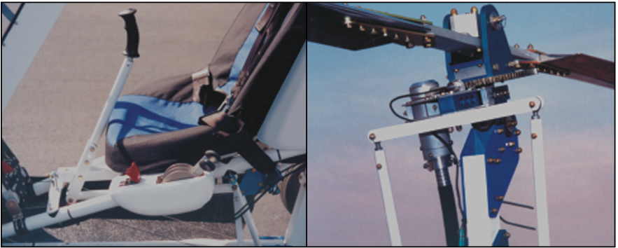
Figure 17-1. A common method of transferring cyclic control inputs to the rotor head is through the use of push-pull tubes, located outboard of the rotor mast pictured on the right.
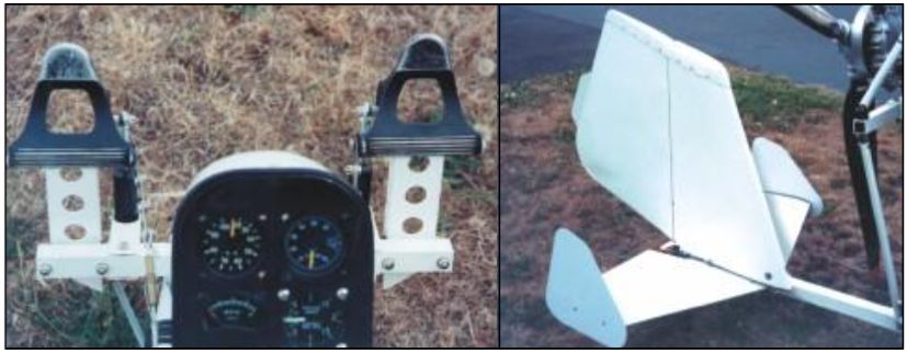
Figure 17-3. Foot pedals provide rudder control and operation is similar to that of an airplane.
for you to become familiar with the unique throttle characteristics and engine responses for a particular gyroplane.
Rudder
The rudder is operated by foot pedals in the cockpit and provides a means to control yaw movement of the aircraft. [Figure 17-3] On a gyroplane, this control is achieved in a manner more similar to the rudder of an airplane than to the antitorque pedals of a helicopter. The rudder is used to maintain coordinated flight, and at times may also require inputs to compensate for propeller torque. Rudder sensitivity and effectiveness are directly proportional to the velocity of airflow over the rudder surface. Consequently, many gyroplane rudders are located in the propeller slipstream and provide excellent control while the engine is developing thrust. This type of rudder configuration, however, is less effective and requires greater deflection when the engine is idled or stopped.
Horizontal tail surfaces
The horizontal tail surfaces on most gyroplanes are not controllable by the pilot. These fixed surfaces, or stabilizers, are incorporated into gyroplane designs to increase the pitch stability of the aircraft. Some gyro- planes use very little, if any, horizontal surface. This translates into less stability, but a higher degree of maneuverability. When used, a moveable horizontal surface, or elevator, adds additional pitch control of the aircraft. On early tractor configured gyroplanes, the elevator served an additional function of deflecting the propeller slipstream up and through the rotor to assist in prerotation.
Collective control
The collective control provides a means to vary the rotor blade pitch of all the blades at the same time, and is available only on more advanced gyroplanes. When incorporated into the rotor head design, the collective allows jump takeoffs when the blade inertia is sufficient. Also, control of in-flight rotor r.p.m. is available to enhance cruise and landing performance. A simple two position collective does not allow unlimited control of blade pitch, but instead has one position for prerotation and another position for flight. This is a performance compromise but reduces pilot workload by simplifying control of the rotor system.


