The diversity of gyroplane designs available today yields a wide variety of capability and performance. For safe operation, you must be thoroughly familiar with the procedures and limitations for your particular aircraft along with other factors that may affect the safety of your flight.
Preflight
As pilot in command, you are the final authority in determining the airworthiness of your aircraft. Adherence to a preflight checklist greatly enhances your ability to evaluate the fitness of your gyroplane by ensuring that a complete and methodical inspection of all components is performed. [Figure 20-1] For aircraft without a formal checklist, it is prudent to create one that is specific to the aircraft to be sure that important items are not overlooked. To determine the status of required inspections, a preflight review of the aircraft records is also necessary.
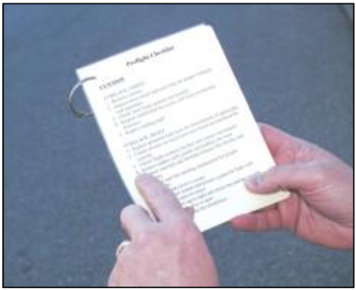
Figure 20-1. A checklist is extremely useful in conducting a thorough preflight inspection.
COCKPIT MANAGEMENT
As in larger aircraft, cockpit management is an important skill necessary for the safe operation of a gyroplane. Intrinsic to these typically small aircraft is a limited amount of space that must be utilized to its potential. The placement and accessibility of charts, writing materials, and other necessary items must be carefully considered. Gyroplanes with open cockpits add the challenge of coping with wind, which further increases the need for creative and resourceful cockpit management for optimum efficiency.
Engine starting
The dissimilarity between the various types of engines used for gyroplane propulsion necessitates the use of an engine start checklist. Again, when a checklist is not provided, it is advisable to create one for the safety of yourself and others, and to prevent inadvertent damage to the engine or propeller. Being inherently dangerous, the propeller demands special attention during engine starting procedures. Always ensure that the propeller area is clear prior to starting. In addition to providing an added degree of safety, being thoroughly familiar with engine starting procedures and characteristics can also be very helpful in starting an engine under various weather conditions.
Taxiing
The ability of the gyroplane to be taxied greatly enhances its utility. However, a gyroplane should not be taxied in close proximity to people or obstructions while the rotor is turning. In addition, taxi speed should be limited to no faster than a brisk walk in ideal conditions, and adjusted appropriately according to the circumstances.
BLADE FLAP
On a gyroplane with a semi-rigid, teeter-head rotor system, blade flap may develop if too much airflow passes through the rotor system while it is operating at low
r.p.m. This is most often the result of taxiing too fast for a given rotor speed. Unequal lift acting on the advancing and retreating blades can cause the blades to teeter to the maximum allowed by the rotor head design. The blades then hit the teeter stops, creating a vibration that may be felt in the cyclic control. The frequency of the vibration corresponds to the speed of the rotor, with the blades hitting the stops twice during each revolution. If the flapping is not controlled, the situation can grow worse as the blades begin to flex and bend. Because the system is operating at low r.p.m., there is not enough centrifugal force acting on the blades to keep them rigid. The shock of hitting the teeter stops combined with uneven lift along the length of the blade causes an undulation to begin, which can increase in severity if allowed to progress. In extreme cases, a rotor blade may strike the ground or propeller. [Figure 20-2]
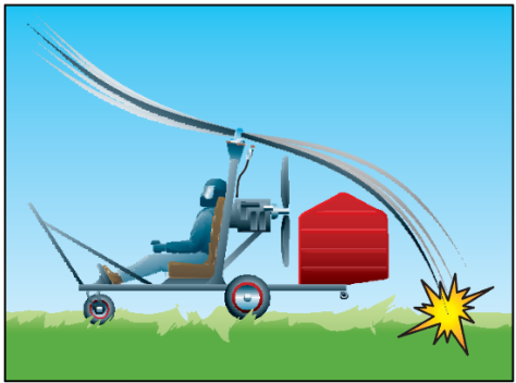
Figure 20-2. Taxiing too fast or gusting winds can cause blade flap in a slow turning rotor. If not controlled, a rotor blade may strike the ground.
To avoid the onset of blade flap, always taxi the gyro- plane at slow speeds when the rotor system is at low r.p.m. Consideration must also be given to wind speed and direction. If taxiing into a 10-knot headwind, for example, the airflow through the rotor will be 10 knots faster than the forward speed of the gyroplane, so the taxi speed should be adjusted accordingly. When pre- rotating the rotor by taxiing with the rotor disc tilted aft, allow the rotor to accelerate slowly and smoothly. In the event blade flap is encountered, apply forward cyclic to reduce the rotor disc angle and slow the gyro- plane by reducing throttle and applying the brakes, if needed. [Figure 20-3]
Before takeoff
For the amateur-built gyroplane using single ignition and a fixed trim system, the before takeoff check is quite simple. The engine should be at normal operating temperature, and the area must be clear for prerotation. Certificated gyroplanes using conventional aircraft engines have a checklist that includes items specific to the powerplant. These normally include, but are not limited to, checks for magneto drop, carburetor heat, and, if a constant speed propeller is installed, that it be cycled for proper operation.
Following the engine run-up is the procedure for accomplishing prerotation. This should be reviewed and committed to memory, as it typically requires both hands to perform.
PREROTATION
Prerotation of the rotor can take many forms in a gyroplane. The most basic method is to turn the rotor blades by hand. On a typical gyroplane with a counter- clockwise rotating rotor, prerotation by hand is done on the right side of the rotor disk. This allows body movement to be directed away from the propeller to minimize the risk of injury. Other methods of prerota- tion include using mechanical, electrical, or hydraulic means for the initial blade spin-up. Many of these systems can achieve only a portion of the rotor speed that is necessary for takeoff. After the prerotator is disengaged, taxi the gyroplane with the rotor disk tilted aft to allow airflow through the rotor. This increases rotor speed to flight r.p.m. In windy conditions, facing the gyroplane into the wind during prerotation assists in achieving the highest possible rotor speed from the prerotator. A factor often overlooked that can negatively affect the prerotation speed is the cleanliness of the rotor blades. For maximum efficiency, it is recom- mended that the rotor blades be cleaned periodically. By obtaining the maximum possible rotor speed through the use of proper prerotation techniques, you
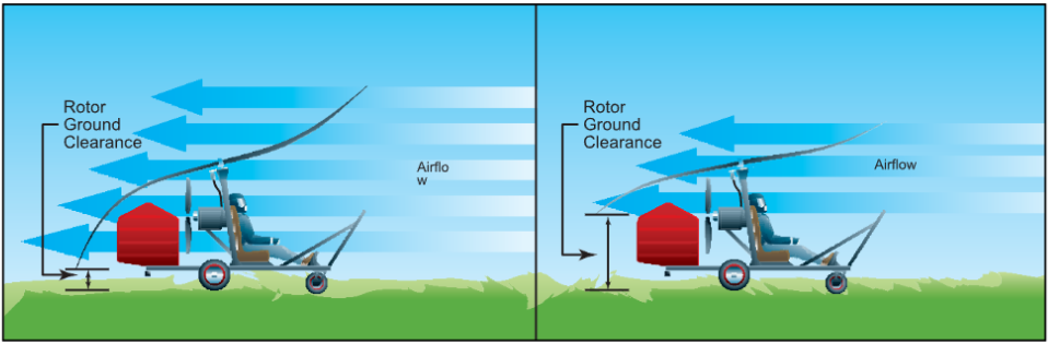
Figure 20-3. Decreasing the rotor disc angle of attack with forward cyclic can reduce the excessive amount of airflow causing the blade flap. This also allows greater clearance between the rotor blades and the surface behind the gyroplane, minimizing the chances of a blade striking the ground.
minimize the length of the ground roll that is required to get the gyroplane airborne.
The prerotators on certificated gyroplanes remove the possibility of blade flap during prerotation. Before the clutch can be engaged, the pitch must be removed from the blades. The rotor is then prerotated with a 0° angle of attack on the blades, which prevents lift from being produced and precludes the possibility of flapping. When the desired rotor speed is achieved, blade pitch is increased for takeoff.
Takeoff
Takeoffs are classified according to the takeoff surface, obstructions, and atmospheric conditions. Each type of takeoff assumes that certain conditions exist. When conditions dictate, a combination of takeoff techniques can be used. Two important speeds used for takeoff and initial climb out are VX and VY. VX is defined as the speed that provides the best angle of climb, and will yield the maximum altitude gain over a given distance. This speed is normally used when obstacles on the ground are a factor. Maintaining VY speed ensures the aircraft will climb at its maximum rate, providing the most altitude gain for a given period of time. [Figure 20-4] Prior to any takeoff or maneuver, you should ensure that the area is clear of other traffic.
NORMAL TAKEOFF
The normal takeoff assumes that a prepared surface of adequate length is available and that there are no high obstructions to be cleared within the takeoff path. The normal takeoff for most amateur-built gyroplanes is accomplished by prerotating to sufficient rotor r.p.m. to prevent blade flapping and tilting the rotor back with cyclic control. Using a speed of 20 to 30 m.p.h., allow the rotor to accelerate and begin producing lift. As lift increases, move the cyclic forward to decrease the pitch angle on the rotor disc. When appreciable lift is being produced, the nose of the aircraft rises, and you can feel an increase in drag. Using coordinated throttle and flight control inputs, balance the gyroplane on the main gear without the nose wheel or tail wheel in contact with the surface. At this point, smoothly increase power to full thrust and hold the nose at takeoff attitude with cyclic pressure. The gyroplane will lift off at or near the minimum power required speed for the aircraft. VX should be used for the initial climb, then VY for the remainder of the climb phase.
A normal takeoff for certificated gyroplanes is accomplished by prerotating to a rotor r.p.m. slightly above that required for flight and disengaging the rotor drive. The brakes are then released and full power is applied. Lift off will not occur until the blade pitch is increased to the normal in-flight setting and the rotor disk tilted
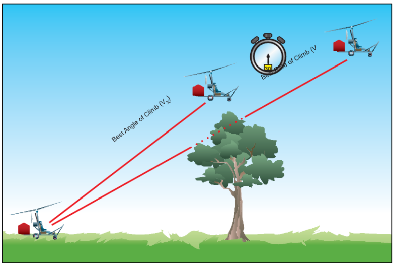
Figure 20-4. Best angle-of-climb (VX) speed is used when obstacles are a factor. VY provides the most altitude gain for a given amount of time.
aft. This is normally accomplished at approximately 30 to 40 m.p.h. The gyroplane should then be allowed to accelerate to VX for the initial climb, followed by VY for the remainder of the climb. On any takeoff in a gyroplane, engine torque causes the aircraft to roll opposite the direction of propeller rotation, and adequate compensation must be made.
CROSSWIND TAKEOFF
A crosswind takeoff is much like a normal takeoff, except that you have to use the flight controls to compensate for the crosswind component. The term crosswind component refers to that part of the wind which acts at right angles to the takeoff path. Before attempting any crosswind takeoff, refer to the flight manual, if available, or the manufacturer’s recommendations for any limitations.
Begin the maneuver by aligning the gyroplane into the wind as much as possible. At airports with wide runways, you might be able to angle your takeoff roll down the runway to take advantage of as much head- wind as you can. As airspeed increases, gradually tilt the rotor into the wind and use rudder pressure to maintain runway heading. In most cases, you should accelerate to a speed slightly faster than normal liftoff speed. As you reach takeoff speed, the downwind wheel lifts off the ground first, followed by the upwind wheel. Once airborne, remove the cross-control inputs and establish a crab, if runway heading is to be maintained. Due to the maneuverability of the gyroplane, an immediate turn into the wind after lift off can be safely executed, if this does not cause a conflict with existing traffic.
COMMON ERRORS FOR NORMAL AND CROSSWIND TAKEOFFS
- Failure to check rotor for proper operation, track, and r.p.m. prior to takeoff.
- Improper initial positioning of flight controls.
- Improper application of power.
- Poor directional control.
- Failure to lift off at proper airspeed.
- Failure to establish and maintain proper climb attitude and airspeed.
- Drifting from the desired ground track during the climb.
SHORT-FIELD TAKEOFF
Short-field takeoff and climb procedures may be required when the usable takeoff surface is short, or when it is restricted by obstructions, such as trees, powerlines, or buildings, at the departure end. The technique is identical to the normal takeoff, with performance being optimized during each phase. Using the help from wind and propwash, the maximum rotor r.p.m. should be attained from the prerotator and full power applied as soon as appreciable lift is felt. VX climb speed should be maintained until the obstruction is cleared. Familiarity with the rotor acceleration characteristics and proper technique are essential for optimum short-field performance.If the prerotator is capable of spinning the rotor in excess of normal flight r.p.m., the stored energy may be used to enhance short-field performance. Once maxi- mum rotor r.p.m. is attained, disengage the rotor drive, release the brakes, and apply power. As airspeed and rotor r.p.m. increase, apply additional power until full power is achieved. While remaining on the ground, accelerate the gyroplane to a speed just prior to VX. At that point, tilt the disk aft and increase the blade pitch to the normal in-flight setting. The climb should be at a speed just under VX until rotor r.p.m. has dropped to normal flight r.p.m. or the obstruction has been cleared. When the obstruction is no longer a factor, increase the airspeed to VY.
COMMON ERRORS
- Failure to position gyroplane for maximum utilization of available takeoff area.
- Failure to check rotor for proper operation, track, and r.p.m. prior to takeoff.
- Improper initial positioning of flight controls.
- Improper application of power.
- Improper use of brakes.
- Poor directional control.
- Failure to lift off at proper airspeed.
- Failure to establish and maintain proper climb attitude and airspeed.
- Drifting from the desired ground track during the climb.
HIGH-ALTITUDE TAKEOFF
A high-altitude takeoff is conducted in a manner very similar to that of the short-field takeoff, which achieves maximum performance from the aircraft during each phase of the maneuver. One important consideration is that at higher altitudes, rotor r.p.m. is higher for a given blade pitch angle. This higher speed is a result of thinner air, and is necessary to produce the same amount of lift. The inertia of the excess rotor speed should not be used in an attempt to enhance climb performance. Another important consideration is the effect of altitude on engine performance. As altitude increases, the amount of oxygen available for combustion decreases. In normally aspirated engines, it may be necessary to
Normally Aspirated—An engine that does not compensate for decreases in atmospheric pressure through turbocharging or other means.
adjust the fuel/air mixture to achieve the best possible power output. This process is referred to as “leaning the mixture.” If you are considering a high-altitude takeoff, and it appears that the climb performance limit of the gyroplane is being approached, do not attempt a takeoff until more favorable conditions exist.
SOFT-FIELD TAKEOFF
A soft field may be defined as any takeoff surface that measurably retards acceleration during the takeoff roll. The objective of the soft-field takeoff is to transfer the weight of the aircraft from the landing gear to the rotor as quickly and smoothly as possible to eliminate the drag caused by surfaces, such as tall grass, soft dirt, or snow. This takeoff requires liftoff at a speed just above the minimum level flight speed for the aircraft. Due to design, many of the smaller gyroplanes have a limited pitch attitude available, as tail contact with the ground prevents high pitch attitudes until in flight. At mini- mum level flight speed, the pitch attitude is often such that the tail wheel is lower than the main wheels. When performing a soft-field takeoff, these aircraft require slightly higher liftoff airspeeds to allow for proper tail clearance.
COMMON ERRORS
- Failure to check rotor for proper operation, track, and r.p.m. prior to takeoff.
- Improper initial positioning of flight controls.
- Improper application of power.
- Allowing gyroplane to lose momentum by slowing or stopping on takeoff surface prior to initiating takeoff.
- Poor directional control.
- Improper pitch attitude during lift-off.
- Settling back to takeoff surface after becoming airborne.
- Failure to establish and maintain proper climb attitude and airspeed.
- Drifting from the desired ground track during the climb.
JUMP TAKEOFF
Gyroplanes with collective pitch change, and the ability to prerotate the rotor system to speeds approximately 50 percent higher than those required for normal flight, are capable of achieving extremely short takeoff rolls. Actual jump takeoffs can be performed under the proper conditions. A jump takeoff requires no ground roll, making it the most effective soft-field and crosswind takeoff procedure. [Figure 20-5] A jump takeoff is possible because the energy stored in the blades, as a result of the higher rotor r.p.m., is used to keep the gyroplane airborne as it accelerates through
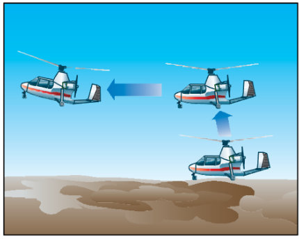
Figure 20-5. During a jump takeoff, excess rotor inertia is used to lift the gyroplane nearly vertical, where it is then accelerated through minimum level flight speed.
minimum level flight speed. Failure to have sufficient rotor r.p.m. for a jump takeoff results in the gyroplane settling back to the ground. Before attempting a jump takeoff, it is essential that you first determine if it is possible given the existing conditions by consulting the relevant performance chart. Should conditions of weight, altitude, temperature, or wind leave the successful outcome of the maneuver in doubt, it should not be attempted.
The prudent pilot may also use a “rule of thumb” for predicting performance before attempting a jump take- off. As an example, suppose that a particular gyroplane is known to be able to make a jump takeoff and remain airborne to accelerate to VX at a weight of 1,800 pounds and a density altitude of 2,000 feet. Since few takeoffs are made under these exact conditions, compensation must be made for variations in weight, wind, and density altitude. The “rule of thumb” being used for this particular aircraft stipulates that 1,000 feet of density altitude equates with 10 m.p.h. wind or 100 pounds of gross weight. To use this equation, you must first deter- mine the density altitude. This is accomplished by setting your altimeter to the standard sea level pressure setting of 29.92 inches of mercury and reading the pressure altitude. Next, you must correct for nonstandard temperature. Standard temperature at sea level is 59°F (15°C) and decreases 3.5°F (2°C) for every additional
Density Altitude—Pressure altitude corrected for nonstandard temperature. This is a theoretical value that is used in determining aircraft performance.
one thousand feet of pressure altitude. [Figure 20-6] Once you have determined the standard temperature for your pressure altitude, compare it with the actual existing conditions. For every 10°F (5.5°C) the actual temperature is above standard, add 750 feet to the pressure altitude to estimate the density altitude. If the density altitude is above 2,000 feet, a jump takeoff in this aircraft should not be attempted unless wind and/or a weight reduction would compensate for the decrease in performance. Using the equation, if the density altitude is 3,000 feet (1,000 feet above a satisfactory jump density altitude), a reduction of 100 pounds in gross weight or a 10 m.p.h. of wind would still allow a satisfactory jump takeoff. Additionally, a reduction of 50 pounds in weight combined with a 5 m.p.h. wind would also allow a satisfactory jump. If it is determined that a jump takeoff should not be conducted because the weight cannot be reduced or an appropriate wind is not blowing, then consideration should be given to a rolling takeoff. A takeoff roll of 10 m.p.h. is equivalent to a wind speed of 10 m.p.h. or a reduction of 100 pounds in gross weight. It is important to note that a jump takeoff is predicated on having achieved a specific rotor r.p.m. If this r.p.m. has not been attained, performance is unpredictable, and the maneuver should not be attempted.
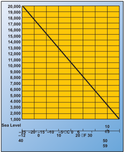
Figure 20-6. Standard temperature chart.
Basic flight maneuvers
Conducting flight maneuvers in a gyroplane is different than in most other aircraft. Because of the wide variety in designs, many gyroplanes have only basic instruments available, and the pilot is often exposed to the airflow. In addition, the visual clues found on other aircraft, such as cowlings, wings, and windshields might not be part of your gyroplane’s design. Therefore, much more reliance is placed on pilot interpretation of flight attitude and the “feel” of the gyroplane than in other types of aircraft. Acquiring the skills to precisely control a gyroplane can be a challenging and rewarding experience, but requires dedication and the direction of a competent instructor.
STRAIGHT-AND-LEVEL FLIGHT
Straight-and-level flight is conducted by maintaining a constant altitude and a constant heading. In flight, a gyroplane essentially acts as a plumb suspended from the rotor. As such, torque forces from the engine cause the airframe to be deflected a few degrees out of the vertical plane. This very slight “out of vertical” condition should be ignored and the aircraft flown to maintain a constant heading.
The throttle is used to control airspeed. In level flight, when the airspeed of a gyroplane increases, the rotor disc angle of attack must be decreased. This causes pitch control to become increasingly more sensitive. [Figure 20-7] As this disc angle becomes very small, it is possible to overcontrol a gyroplane when encountering turbulence. For this reason, when extreme turbulence is encountered or expected, airspeed should be decreased. Even in normal conditions, a gyroplane requires constant attention to maintain straight-and- level flight. Although more stable than helicopters, gyroplanes are less stable than airplanes. When cyclic trim is available, it should be used to relieve any stick forces required during stabilized flight.
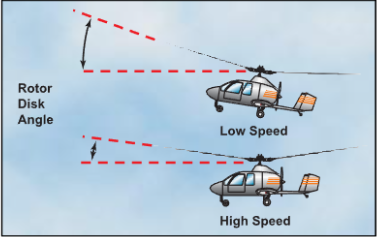
Figure 20-7. The angle of the rotor disc decreases at higher cruise speeds, which increases pitch control sensitivity.
CLIMBS
A climb is achieved by adding power in excess of what is required for straight-and-level flight at a particular airspeed. The amount of excess power used is directly proportional to the climb rate. For maneuvers when
maximum performance is desired, two important climb speeds are best angle-of-climb speed and best rate-of- climb speed.
Because a gyroplane cannot be stalled, it may be tempt- ing to increase the climb rate by decreasing airspeed. This practice, however, is self-defeating. Operating below the best angle-of-climb speed causes a diminish- ing rate of climb. In fact, if a gyroplane is slowed to the minimum level flight speed, it requires full power just to maintain altitude. Operating in this performance realm, sometimes referred to as the “backside of the power curve,” is desirable in some maneuvers, but can be hazardous when maximum climb performance is required. For further explanation of a gyroplane power curve, see Flight at Slow Airspeeds, which is discussed later in this chapter.
DESCENTS
A descent is the result of using less power than that required for straight-and-level flight at a particular airspeed. Varying engine power during a descent allows you to choose a variety of descent profiles. In a power-off descent, the minimum descent rate is achieved by using the airspeed that would normally be used for level flight at minimum power, which is also very close to the speed used for the best angle of climb. When distance is a factor during a power-off descent, maximum gliding distance can be achieved by maintaining a speed very close to the best rate-of-climb airspeed. Because a gyroplane can be safely flown down to zero airspeed, a common error in this type of descent is attempting to extend the glide by raising the pitch attitude. The result is a higher rate of descent and less distance being covered. For this reason, proper glide speed should be adhered to closely. Should a strong headwind exist, while attempting to achieve the maximum distance during a glide, a rule of thumb to achieve the greatest distance is to increase the glide speed by approximately 25 percent of the headwind. The attitude of the gyroplane for best glide performance is learned with experience, and slight pitch adjustments are made for the proper airspeed. If a descent is needed to lose excess altitude, slowing the gyroplane to below the best glide speed increases the rate of descent. Typically, slowing to zero airspeed results in a descent rate twice that of maintaining the best glide speed.
TURNS
Turns are made in a gyroplane by banking the rotor disc with cyclic control. Once the area, in the direction of the turn, has been cleared for traffic, apply sideward pressure on the cyclic until the desired bank angle is achieved. The speed at which the gyroplane enters the bank is dependent on how far the cyclic is displaced. When the desired bank angle is reached, return the cyclic to the neutral position. The rudder pedals are used to keep the gyroplane in longitudinal trim throughout the turn, but not to assist in establishing the turn.
The bank angle used for a turn directly affects the rate of turn. As the bank is steepened, the turn rate increases, but more power is required to maintain altitude. A bank angle can be reached where all available power is required, with any further increase in bank resulting in a loss of airspeed or altitude. Turns during a climb should be made at the minimum angle of bank necessary, as higher bank angles would require more power that would otherwise be available for the climb. Turns while gliding increase the rate of descent and may be used as an effective way of losing excess altitude.
SLIPS
A slip occurs when the gyroplane slides sideways toward the center of the turn. [Figure 20-8] It is caused by an insufficient amount of rudder pedal in the direction of the turn, or too much in the direction opposite the turn. In other words, holding improper rudder pedal pressure keeps the nose from following the turn, the gyroplane slips sideways toward the center of the turn.
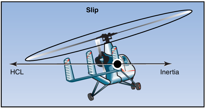
Figure 20-8. During a slip, the rate of turn is too slow for the angle of bank used, and the horizontal component of lift (HCL) exceeds inertia. You can reestablish equilibrium by decreasing the angle of bank, increasing the rate of turn by applying rudder pedal, or a combination of the two.
SKIDS
A skid occurs when the gyroplane slides sideways away from the center of the turn. [Figure 20-9] It is caused by too much rudder pedal pressure in the direction of the turn, or by too little in the direction opposite the turn. If the gyroplane is forced to turn faster with increased pedal pressure instead of by increasing the degree of
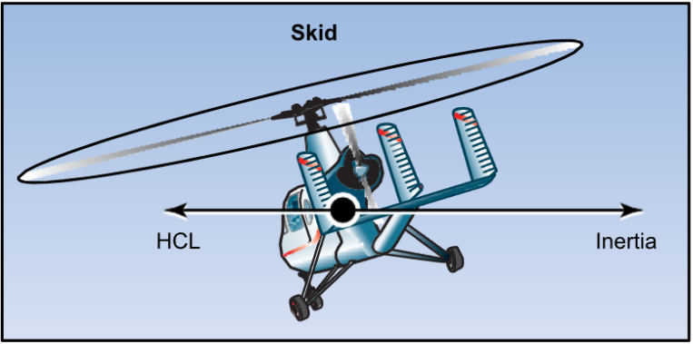
Figure 20-9. During a skid, inertia exceeds the HCL. To reestablish equilibrium, increase the bank angle or reduce the rate of turn by applying rudder pedal. You may also use a combination of these two corrections.
bank, it skids sideways away from the center of the turn instead of flying in its normal curved pattern.
COMMON ERRORS DURING BASIC FLIGHT MANEUVERS
- Improper coordination of flight controls.
- Failure to cross-check and correctly interpret outside and instrument references.
- Using faulty trim technique.
STEEP TURNS
A steep turn is a performance maneuver used in training that consists of a turn in either direction at a bank angle of approximately 40°. The objective of performing steep turns is to develop smoothness, coordination, orientation, division of attention, and control techniques.
Prior to initiating a steep turn, or any other flight maneuver, first complete a clearing turn to check the area for traffic. To accomplish this, you may execute either one 180° turn or two 90° turns in opposite directions. Once the area has been cleared, roll the gyroplane into a 40° angle-of-bank turn while smoothly adding power and slowly moving the cyclic aft to maintain altitude. Maintain coordinated flight with proper rudder pedal pressure. Throughout the turn, cross-reference visual cues outside the gyroplane with the flight instruments, if available, to maintain a constant altitude and angle of bank. Anticipate the roll-out by leading the roll-out heading by approximately 20°. Using section lines or prominent landmarks to aid in orientation can be helpful in rolling out on the proper heading. During roll-out, gradually return the cyclic to the original position and reduce power to maintain altitude and airspeed.
COMMON ERRORS
- Improper bank and power coordination during entry and rollout.
- Uncoordinated use of flight controls.
- Exceeding manufacturer’s recommended maxi- mum bank angle.
- Improper technique in correcting altitude deviations.
- Loss of orientation.
- Excessive deviation from desired heading during rollout.
Ground reference maneuvers
Ground reference maneuvers are training exercises flown to help you develop a division of attention between the flight path and ground references, while controlling the gyroplane and watching for other aircraft in the vicinity. Prior to each maneuver, a clearing turn should be accomplished to ensure the practice area is free of conflicting traffic.
RECTANGULAR COURSE
The rectangular course is a training maneuver in which the ground track of the gyroplane is equidistant from all sides of a selected rectangular area on the ground. [Figure 20-10] While performing the maneuver, the altitude and airspeed should be held constant. The rectangular course helps you to develop a recognition of a drift toward or away from a line parallel to the intended ground track. This is helpful in recognizing drift toward or from an airport runway during the various legs of the airport traffic pattern.
For this maneuver, pick a square or rectangular field, or an area bounded on four sides by section lines or roads, where the sides are approximately a mile in length. The area selected should be well away from other air traffic. Fly the maneuver approximately 600 to 1,000 feet above the ground, which is the altitude usually required for an airport traffic pattern. You should fly the gyroplane parallel to and at a uniform distance, about one-fourth to one-half mile, from the field boundaries, not above the boundaries. For best results, position your flight path outside the field boundaries just far enough away that they may be easily observed. You should be able to see the edges of the selected field while seated in a normal position and looking out the side of the gyroplane during either a left-hand or right- hand course. The distance of the ground track from the edges of the field should be the same regardless of whether the course is flown to the left or right. All turns should be started when your gyroplane is abeam the corners of the field boundaries. The bank normally should not exceed 30°.
Although the rectangular course may be entered from any direction, this discussion assumes entry on a down- wind heading. As you approach the field boundary on the downwind leg, you should begin planning for your turn to the crosswind leg. Since you have a tailwind on the downwind leg, the gyroplane’s groundspeed is increased (position 1). During the turn onto the cross- wind leg, which is the equivalent of the base leg in a traffic pattern, the wind causes the gyroplane to drift away from the field. To counteract this effect, the roll- in should be made at a fairly fast rate with a relatively steep bank (position 2).
As the turn progresses, the tailwind component decreases, which decreases the groundspeed. Consequently, the bank angle and rate of turn must be reduced gradually to ensure that upon completion of the turn, the crosswind ground track continues to be the same distance from the edge of the field. Upon completion of the turn, the gyroplane should be level and
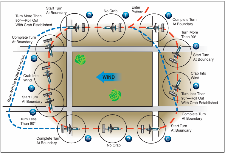
Figure 20-10. Rectangular course. The numbered positions in the text refer to the numbers in this illustration.
aligned with the downwind corner of the field. However, since the crosswind is now pushing you away from the field, you must establish the proper drift correction by flying slightly into the wind. Therefore, the turn to crosswind should be greater than a 90° change in heading (position 3). If the turn has been made properly, the field boundary again appears to be one-fourth to one-half mile away. While on the cross- wind leg, the wind correction should be adjusted, as necessary, to maintain a uniform distance from the field boundary (position 4).
As the next field boundary is being approached (position 5), plan the turn onto the upwind leg. Since a wind correction angle is being held into the wind and toward the field while on the crosswind leg, this next turn requires a turn of less than 90°. Since the crosswind becomes a headwind, causing the groundspeed to decrease during this turn, the bank initially must be medium and progressively decreased as the turn proceeds. To complete the turn, time the rollout so that the gyroplane becomes level at a point aligned with the corner of the field just as the longitudinal axis of the gyroplane again becomes parallel to the field boundary (position 6). The distance from the field boundary should be the same as on the other sides of the field.
On the upwind leg, the wind is a headwind, which results in an decreased groundspeed (position 7). Consequently, enter the turn onto the next leg with a fairly slow rate of roll-in, and a relatively shallow bank (position 8). As the turn progresses, gradually increase the bank angle because the headwind component is diminishing, resulting in an increasing groundspeed. During and after the turn onto this leg, the wind tends to drift the gyroplane toward the field boundary. To compensate for the drift, the amount of turn must be less than 90° (position 9).
Again, the rollout from this turn must be such that as the gyroplane becomes level, the nose of the gyroplane is turned slightly away the field and into the wind to correct for drift. The gyroplane should again be the same distance from the field boundary and at the same altitude, as on other legs. Continue the crosswind leg until the downwind leg boundary is approached (position 10). Once more you should anticipate drift and turning radius. Since drift correction was held on the crosswind leg, it is necessary to turn greater than 90° to align the gyroplane parallel to the downwind leg boundary. Start this turn with a medium bank angle, gradually increasing it to a steeper bank as the turn progresses. Time the rollout to assure paralleling the boundary of the field as the gyroplane becomes level (position 11).
If you have a direct headwind or tailwind on the upwind and downwind leg, drift should not be encountered. However, it may be difficult to find a situation where the wind is blowing exactly parallel to the field boundaries. This makes it necessary to use a slight wind correction angle on all the legs. It is important to anticipate the turns to compensate for groundspeed, drift, and turning radius. When the wind is behind the gyroplane, the turn must be faster and steeper; when it is ahead of the gyroplane, the turn must be slower and shallower. These same techniques apply while flying in an airport traffic pattern.
S-TURNS
Another training maneuver you might use is the S-turn, which helps you correct for wind drift in turns. This maneuver requires turns to the left and right. The refer- ence line used, whether a road, railroad, or fence, should be straight for a considerable distance and should extend as nearly perpendicular to the wind as possible.
The object of S-turns is to fly a pattern of two half circles of equal size on opposite sides of the reference line. [Figure 20-11] The maneuver should be performed at a constant altitude of 600 to 1,000 feet above the terrain. S-turns may be started at any point; however, during early training it may be beneficial to start on a downwind heading. Entering downwind permits the immediate selection of the steepest bank
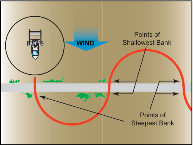
Figure 20-11. S-turns across a road.
that is desired throughout the maneuver. The discus- sion that follows is based on choosing a reference line that is perpendicular to the wind and starting the maneuver on a downwind heading.
As the gyroplane crosses the reference line, immediately establish a bank. This initial bank is the steepest used throughout the maneuver since the gyroplane is headed directly downwind and the groundspeed is at its highest. Gradually reduce the bank, as necessary, to describe a ground track of a half circle. Time the turn so that as the rollout is completed, the gyroplane is crossing the reference line perpendicular to it and head- ing directly upwind. Immediately enter a bank in the opposite direction to begin the second half of the “S.” Since the gyroplane is now on an upwind heading, this bank (and the one just completed before crossing the reference line) is the shallowest in the maneuver. Gradually increase the bank, as necessary, to describe a ground track that is a half circle identical in size to the one previously completed on the other side of the refer- ence line. The steepest bank in this turn should be attained just prior to rollout when the gyroplane is approaching the reference line nearest the downwind heading. Time the turn so that as the rollout is com- plete, the gyroplane is perpendicular to the reference line and is again heading directly downwind.
In summary, the angle of bank required at any given point in the maneuver is dependent on the ground- speed. The faster the groundspeed, the steeper the bank; the slower the groundspeed, the shallower the bank. To express it another way, the more nearly the gyroplane is to a downwind heading, the steeper the bank; the more nearly it is to an upwind heading, the shallower the bank. In addition to varying the angle of bank to correct for drift in order to maintain the proper radius of turn, the gyroplane must also be flown with a drift correction angle (crab) in relation to its ground track; except of course, when it is on direct upwind or downwind headings or there is no wind. One would normally think of the fore and aft axis of the gyroplane as being tangent to the ground track pattern at each point. However, this is not the case. During the turn on the upwind side of the reference line (side from which the wind is blowing), crab the nose of the gyroplane toward the outside of the circle. During the turn on the downwind side of the reference line (side of the reference line opposite to the direction from which the wind is blowing), crab the nose of the gyroplane toward the inside of the circle. In either case, it is obvious that the gyroplane is being crabbed into the wind just as it is when trying to maintain a straight ground track. The amount of crab depends upon the wind velocity and how nearly the gyroplane is to a crosswind position. The stronger the wind, the greater the crab angle at any given position for a turn of a given radius. The more nearly the gyroplane is to a crosswind position, the greater the crab angle. The maximum crab angle should be at the point of each half circle farthest from the reference line.
A standard radius for S-turns cannot be specified, since the radius depends on the airspeed of the gyroplane, the
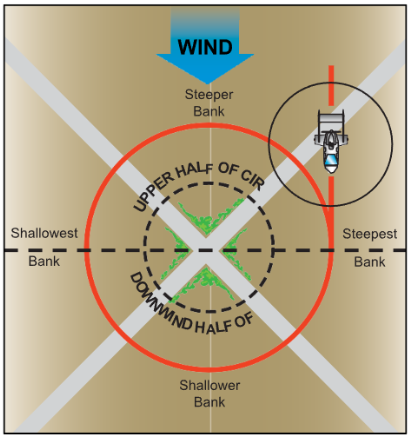
Figure 20-12. Turns around a point.
velocity of the wind, and the initial bank chosen for entry.
TURNS AROUND A POINT
This training maneuver requires you to fly constant radius turns around a preselected point on the ground using a maximum bank of approximately 40°, while maintaining a constant altitude. [Figure 20-12] Your objective, as in other ground reference maneuvers, is to develop the ability to subconsciously control the gyro- plane while dividing attention between the flight path and ground references, while still watching for other air traffic in the vicinity.
The factors and principles of drift correction that are involved in S-turns are also applicable in this maneuver. As in other ground track maneuvers, a constant radius around a point will, if any wind exists, require a constantly changing angle of bank and angles of wind correction. The closer the gyroplane is to a direct downwind heading where the groundspeed is greatest, the steeper the bank, and the faster the rate of turn required to establish the proper wind correction angle. The more nearly it is to a direct upwind heading where the groundspeed is least, the shallower the bank, and the slower the rate of turn required to establish the proper wind correction angle. It follows then, that throughout the maneuver, the bank and rate of turn must be gradually varied in proportion to the groundspeed.
The point selected for turns around a point should be prominent and easily distinguishable, yet small enough to present a precise reference. Isolated trees, crossroads, or other similar small landmarks are usu- ally suitable. The point should be in an area away from communities, livestock, or groups of people on the ground to prevent possible annoyance or hazard to others. Since the maneuver is performed between 600 and 1,000 feet AGL, the area selected should also afford an opportunity for a safe emergency landing in the event it becomes necessary.
To enter turns around a point, fly the gyroplane on a downwind heading to one side of the selected point at a distance equal to the desired radius of turn. When any significant wind exists, it is necessary to roll into the initial bank at a rapid rate so that the steepest bank is attained abeam the point when the gyroplane is headed directly downwind. By entering the maneuver while heading directly downwind, the steepest bank can be attained immediately. Thus, if a bank of 40° is desired, the initial bank is 40° if the gyroplane is at the correct distance from the point. Thereafter, the bank is gradually shallowed until the point is reached where the gyroplane is headed directly upwind. At this point, the bank is gradually steepened until the steepest bank is again attained when heading downwind at the initial point of entry.
Just as S-turns require that the gyroplane be turned into the wind, in addition to varying the bank, so do turns around a point. During the downwind half of the circle, the gyroplane’s nose must be progressively turned toward the inside of the circle; during the upwind half, the nose must be progressively turned toward the out- side. The downwind half of the turn around the point may be compared to the downwind side of the S-turn, while the upwind half of the turn around a point may be compared to the upwind side of the S-turn.
As you become experienced in performing turns around a point and have a good understanding of the effects of wind drift and varying of the bank angle and wind correction angle, as required, entry into the maneuver may be from any point. When entering this maneuver at any point, the radius of the turn must be carefully selected, taking into account the wind veloc- ity and groundspeed, so that an excessive bank is not required later on to maintain the proper ground track.
COMMON ERRORS DURING GROUND REFERENCE MANEUVERS
- Faulty entry technique.
- Poor planning, orientation, or division of attention.
- Uncoordinated flight control application.
- Improper correction for wind drift.
- An unsymmetrical ground track during S-turns across a road.
- Failure to maintain selected altitude or airspeed.
- Selection of a ground reference where there is no suitable emergency landing site.
Flight at slow airspeeds
The purpose of maneuvering during slow flight is to help you develop a feel for controlling the gyroplane at slow airspeeds, as well as gain an understanding of how load factor, pitch attitude, airspeed, and altitude control relate to each other.
Like airplanes, gyroplanes have a specific amount of power that is required for flight at various airspeeds, and a fixed amount of power available from the engine. This data can be charted in a graph format. [Figure 20-13] The lowest point of the power required curve represents the speed at which the gyroplane will fly in level flight while using the least amount of power. To fly faster than this speed, or slower, requires more power. While practicing slow flight in a gyroplane, you will likely be operating in the performance realm on the chart that is left of the minimum power required speed. This is often referred to as the “backside of the power curve,” or flying “behind the power curve.” At these speeds, as pitch is increased to slow the gyroplane, more and more power is required to maintain level flight. At the point where maximum power available is being used, no further reduction in airspeed is possible without initiating a descent. This speed is referred to as the minimum level flight speed. Because there is no excess power available for acceleration, recovery from minimum level flight speed requires lowering the nose of the gyroplane and using altitude to regain airspeed. For this reason, it is essential to practice slow flight at altitudes that allow sufficient height for a safe recovery. Unintentionally flying a gyroplane on the backside of the power curve during approach and landing can be extremely hazardous. Should a go-around become necessary, sufficient altitude to regain airspeed and initiate a climb may not be available, and ground contact may be unavoidable.
Flight at slow airspeeds is usually conducted at air- speeds 5 to 10 m.p.h. above the minimum level flight airspeed. When flying at slow airspeeds, it is important that your control inputs be smooth and slow to prevent a rapid loss of airspeed due to the high drag increases with small changes in pitch attitude. In addition, turns should be limited to shallow bank angles. In order to prevent losing altitude during turns, power must be added. Directional control remains very good while flying at slow airspeeds, because of the high velocity slipstream produced by the increased engine power.
Recovery to cruise flight speed is made by lowering the nose and increasing power. When the desired speed is reached, reduce power to the normal cruise power setting.
COMMON ERRORS
- Improper entry technique.
- Failure to establish and maintain an appropriate airspeed.
- Excessive variations of altitude and heading when a constant altitude and heading are specified.
- Use of too steep a bank angle.
- Rough or uncoordinated control technique.
High rate of descent
A gyroplane will descend at a high rate when flown at very low forward airspeeds. This maneuver may be entered intentionally when a steep descent is desired, and can be performed with or without power. An unintentional high rate of descent can also occur as a result
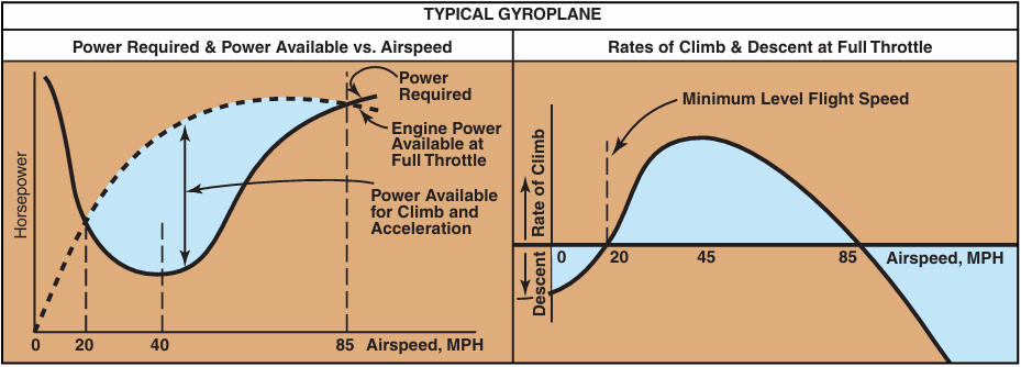
Figure 20-13. The low point on the power required curve is the speed that the gyroplane can fly while using the least amount of power, and is also the speed that will result in a minimum sink rate in a power-off glide.
of failing to monitor and maintain proper airspeed. In powered flight, if the gyroplane is flown below mini- mum level flight speed, a descent results even though full engine power is applied. Further reducing the air- speed with aft cyclic increases the rate of descent. For gyroplanes with a high thrust-to-weight ratio, this maneuver creates a very high pitch attitude. To recover, the nose of the gyroplane must lowered slightly to exchange altitude for an increase in airspeed.
When operating a gyroplane in an unpowered glide, slowing to below the best glide speed can also result in a high rate of descent. As airspeed decreases, the rate of descent increases, reaching the highest rate as forward speed approaches zero. At slow airspeeds without the engine running, there is very little airflow over the tail surfaces and rudder effectiveness is greatly reduced. Rudder pedal inputs must be exaggerated to maintain effective yaw control. To recover, add power, if avail- able, or lower the nose and allow the gyroplane to accelerate to the proper airspeed. This maneuver demonstrates the importance of maintaining the proper glide speed during an engine-out emergency landing. Attempting to stretch the glide by raising the nose results in a higher rate of descent at a lower forward speed, leaving less distance available for the selection of a landing site.
COMMON ERRORS
- Improper entry technique.
- Failure to recognize a high rate of descent.
- Improper use of controls during recovery.
- Initiation of recovery below minimum recovery altitude.
Landings
Landings may be classified according to the landing surface, obstructions, and atmospheric conditions. Each type of landing assumes that certain conditions exist. To meet the actual conditions, a combination of techniques may be necessary.
NORMAL LANDING
The procedure for a normal landing in a gyroplane is predicated on having a prepared landing surface and no significant obstructions in the immediate area. After entering a traffic pattern that conforms to established standards for the airport and avoids the flow of fixed wing traffic, a before landing checklist should be reviewed. The extent of the items on the checklist is dependent on the complexity of the gyroplane, and can include fuel, mixture, carburetor heat, propeller, engine instruments, and a check for traffic.
Gyroplanes experience a slight lag between control input and aircraft response. This lag becomes more apparent during the sensitive maneuvering required for landing, and care must be taken to avoid overcor- recting for deviations from the desired approach path. After the turn to final, the approach airspeed appropri- ate for the gyroplane should be established. This speed is normally just below the minimum power required speed for the gyroplane in level flight. During the approach, maintain this airspeed by making adjust- ments to the gyroplane’s pitch attitude, as necessary. Power is used to control the descent rate.
Approximately 10 to 20 feet above the runway, begin the flare by gradually increasing back pressure on the cyclic to reduce speed and decrease the rate of descent. The gyroplane should reach a near-zero rate of descent approximately 1 foot above the runway with the power at idle. Low airspeed combined with a minimum of propwash over the tail surfaces reduces rudder effectiveness during the flare. If a yaw moment is encountered, use whatever rudder control is required to maintain the desired heading. The gyroplane should be kept laterally level and with the longitudinal axis in the direction of ground track. Landing with sideward motion can damage the landing gear and must be avoided. In a full-flare landing, attempt to hold the gyroplane just off the runway by steadily increasing back pressure on the cyclic. This causes the gyroplane to settle slowly to the runway in a slightly nose-high attitude as forward momentum dissipates.
Ground roll for a full-flare landing is typically under 50 feet, and touchdown speed under 20 m.p.h. If a 20
m.p.h. or greater headwind exists, it may be necessary to decrease the length of the flare and allow the gyro- plane to touch down at a slightly higher airspeed to prevent it from rolling backward on landing. After touchdown, rotor r.p.m. decays rather rapidly. On landings where brakes are required immediately after touchdown, apply them lightly, as the rotor is still car- rying much of the weight of the aircraft and too much braking causes the tires to skid.
SHORT-FIELD LANDING
A short-field landing is necessary when you have a rel- atively short landing area or when an approach must be made over obstacles that limit the available landing area. When practicing short-field landings, assume you are making the approach and landing over a 50-foot obstruction in the approach area.
To conduct a short-field approach and landing, follow normal procedures until you are established on the final approach segment. At this point, use aft cyclic to reduce airspeed below the speed for mini- mum sink. By decreasing speed, sink rate increases and a steeper approach path is achieved, minimizing the distance between clearing the obstacle and making contact with the surface. [Figure 20-14] The approach speed must remain fast enough, however, to allow the flare to arrest the forward and vertical speed of the gyroplane. If the approach speed is too low, the remaining vertical momentum will result in a hard landing. On a short-field landing with a slight headwind, a touchdown with no ground roll is possi- ble. Without wind, the ground roll is normally less than 50 feet.
SOFT-FIELD LANDING
Use the soft-field landing technique when the landing surface presents high wheel drag, such as mud, snow, sand, tall grass or standing water. The objective is to transfer the weight of the gyroplane from the rotor to the landing gear as gently and slowly as possible. With a headwind close to the touchdown speed of the gyroplane, a power approach can be made close to the minimum level flight speed. As you increase the nose pitch attitude just prior to touchdown, add additional power to cushion the landing. However, power should be removed, just as the wheels are ready to touch. This results is a very slow, gentle touchdown. In a strong headwind, avoid allowing the gyroplane to roll rear- ward at touchdown. After touchdown, smoothly and gently lower the nosewheel to the ground. Minimize the use of brakes, and remain aware that the nosewheel could dig in the soft surface.
When no wind exists, use a steep approach similar to a short-field landing so that the forward speed can be dis- sipated during the flare. Use the throttle to cushion the touchdown.
CROSSWIND LANDING
Crosswind landing technique is normally used in gyro- planes when a crosswind of approximately 15 m.p.h. or less exists. In conditions with higher crosswinds, it becomes very difficult, if not impossible, to maintain adequate compensation for the crosswind. In these con- ditions, the slow touchdown speed of a gyroplane allows a much safer option of turning directly into the wind and landing with little or no ground roll. Deciding when to use this technique, however, may be complicated by gusting winds or the characteristics of the particular landing area.
On final approach, establish a crab angle into the wind to maintain a ground track that is aligned with the extended centerline of the runway. Just before touchdown, remove the crab angle and bank the gyroplane slightly into the wind to prevent drift. Maintain longitudinal alignment with the runway using the rudder. In higher crosswinds, if full rudder deflection is not sufficient to maintain alignment with the run- way, applying a slight amount of power can increase rudder effectiveness. The length of the flare should be reduced to allow a slightly higher touchdown speed than that used in a no-wind landing. Touchdown is made on the upwind main wheel first, with the other main wheel settling to the runway as forward momentum is lost. After landing, continue to keep the rotor tilted into the wind to maintain positive control during the rollout.
HIGH-ALTITUDE LANDING
A high-altitude landing assumes a density altitude near the limit of what is considered good climb performance
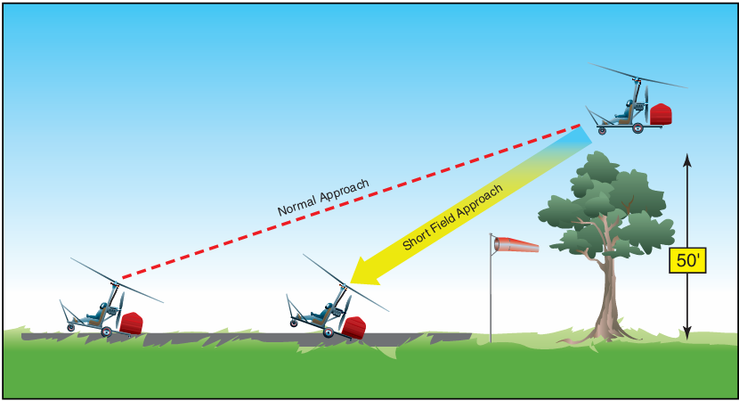
Figure 20-14. The airspeed used on a short-field approach is slower than that for a normal approach, allowing a steeper approach path and requiring less runway.
for the gyroplane. When using the same indicated airspeed as that used for a normal approach at lower altitude, a high density altitude results in higher rotor
r.p.m. and a slightly higher rate of descent. The greater vertical velocity is a result of higher true airspeed as compared with that at low altitudes. When practicing high-altitude landings, it is prudent to first learn normal landings with a flare and roll out. Full flare, no roll landings should not be attempted until a good feel for aircraft response at higher altitudes has been acquired. As with high-altitude takeoffs, it is also important to consider the effects of higher altitude on engine performance.
COMMON ERRORS DURING LANDING
- Failure to establish and maintain a stabilized approach.
- Improper technique in the use of power.
- Improper technique during flare or touchdown.
- Touchdown at too low an airspeed with strong headwinds, causing a rearward roll.
- Poor directional control after touchdown.
- Improper use of brakes.
Go-around
The go-around is used to abort a landing approach when unsafe factors for landing are recognized. If the decision is made early in the approach to go around, normal climb procedures utilizing VX and VY should be used. A late decision to go around, such as after the full flare has been initiated, may result in an airspeed where power required is greater than power available. When this occurs, a touchdown becomes unavoidable and it may be safer to proceed with the landing than to sustain an extended ground roll that would be required to go around. Also, the pitch attitude of the gyroplane in the flare is high enough that the tail would be con- siderably lower than the main gear, and a touch down with power on would result in a sudden pitch down and acceleration of the aircraft. Control of the gyroplane under these circumstances may be difficult. Consequently, the decision to go around should be made as early as possible, before the speed is reduced below the point that power required exceeds power available.
COMMON ERRORS
- Failure to recognize a situation where a go- around is necessary.
- Improper application of power.
- Failure to control pitch attitude.
- Failure to maintain recommended airspeeds.
- Failure to maintain proper track during climb out.
After landing and securing
The after-landing checklist should include such items as the transponder, cowl flaps, fuel pumps, lights, and magneto checks, when so equipped. The rotor blades demand special consideration after landing, as turning rotor blades can be hazardous to others. Never enter an area where people or obstructions are present with the rotor turning. To assist the rotor in slowing, tilt the cyclic control into the prevailing wind or face the gyro- plane downwind. When slowed to under approximately 75 r.p.m., the rotor brake may be applied, if available. Use caution as the rotor slows, as excess taxi speed or high winds could cause blade flap to occur. The blades should be depitched when taxiing if a collective control is available. When leaving the gyroplane, always secure the blades with a tiedown or rotor brake.


