Today helicopters are quite reliable. However emergencies do occur, whether a result of mechanical failure or pilot error. By having a thorough knowledge of the helicopter and its systems, you will be able to more readily handle the situation. In addition, by knowing the conditions that can lead to an emergency, many potential accidents can be avoided.
AUTOROTATION
In a helicopter, an autorotation is a descending maneuver where the engine is disengaged from the main rotor system and the rotor blades are driven solely by the upward flow of air through the rotor. In other words, the engine is no longer supplying power to the main rotor.
The most common reason for an autorotation is an engine failure, but autorotations can also be performed in the event of a complete tail rotor failure, since there is virtually no torque produced in an autorotation. If altitude permits, they can also be used to recover from settling with power. If the engine fails, the freewheeling unit automatically disengages the engine from the main rotor allowing the main rotor to rotate freely.
Essentially, the freewheeling unit disengages anytime the engine r.p.m. is less than the rotor r.p.m.
At the instant of engine failure, the main rotor blades are producing lift and thrust from their angle of attack and velocity. By immediately lowering collective pitch, which must be done in case of an engine failure, lift and drag are reduced, and the helicopter begins an immediate descent, thus producing an upward flow of air through the rotor system. This upward flow of air through the rotor provides sufficient thrust to maintain rotor r.p.m. throughout the descent. Since the tail rotor is driven by the main rotor transmission during autoro-tation, heading control is maintained as in normal flight.
Several factors affect the rate of descent in autorota-tion; density altitude, gross weight, rotor r.p.m., and airspeed. Your primary control of the rate of descent is airspeed. Higher or lower airspeeds are obtained with the cyclic pitch control just as in normal flight.
In theory, you have a choice in the angle of descent varying from a vertical descent to maximum range, which is the minimum angle of descent. Rate of descent is high at zero airspeed and decreases to a minimum at approximately 50 to 60 knots, depending upon the particular helicopter and the factors just mentioned. As the airspeed increases beyond that which gives minimum rate of descent, the rate of descent increases again.
When landing from an autorotation, the energy stored in the rotating blades is used to decrease the rate of descent and make a soft landing. A greater amount of rotor energy is required to stop a helicopter with a high rate of descent than is required to stop a helicopter that is descending more slowly. Therefore, autorotative descents at very low or very high airspeeds are more critical than those performed at the minimum rate of descent airspeed.
Each type of helicopter has a specific airspeed at which a power-off glide is most efficient. The best airspeed is the one which combines the greatest glide range with the slowest rate of descent. The specific airspeed is somewhat different for each type of helicopter, yet certain factors affect all configurations in the same manner. For specific autorotation airspeeds for a particular helicopter, refer to the FAA-approved rotorcraft flight manual.
The specific airspeed for autorotations is established for each type of helicopter on the basis of average weather and wind conditions and normal loading.
When the helicopter is operated with heavy loads in high density altitude or gusty wind conditions, best performance is achieved from a slightly increased airspeed in the descent. For autorotations at low density altitude and light loading, best performance is achieved from a slight decrease in normal airspeed. Following this general procedure of fitting airspeed to existing conditions, you can achieve approximately the same glide angle in any set of circumstances and estimate the touchdown point.
When making turns during an autorotation, generally use cyclic control only. Use of antitorque pedals to assist or speed the turn causes loss of airspeed and downward pitching of the nose. When an autorotation is initiated, sufficient antitorque pedal pressure should be used to maintain straight flight and prevent yawing.
This pressure should not be changed to assist the turn.
Use collective pitch control to manage rotor r.p.m. If rotor r.p.m. builds too high during an autorotation, raise the collective sufficiently to decrease r.p.m. back to the normal operating range. If the r.p.m. begins decreasing, you have to again lower the collective. Always keep the rotor r.p.m. within the established range for your helicopter. During a turn, rotor r.p.m. increases due to the increased back cyclic control pressure, which induces a greater airflow through the rotor system. The r.p.m. builds rapidly and can easily exceed the maximum limit if not controlled by use of collective. The tighter the turn and the heavier the gross weight, the higher the r.p.m.
To initiate an autorotation, other than in a low hover, lower the collective pitch control. This holds true whether performing a practice autorotation or in the event of an in-flight engine failure. This reduces the pitch of the main rotor blades and allows them to continue turning at normal r.p.m. During practice autorotations, maintain the r.p.m. in the green arc with the throttle while lowering collective. Once the collective is fully lowered, reduce engine r.p.m. by decreasing the throttle. This causes a split of the engine and rotor r.p.m. needles.
STRAIGHT-IN AUTOROTATION
A straight-in autorotation implies an autorotation from altitude with no turns. The speed at touchdown and the resulting ground run depends on the rate and amount of flare. The greater the degree of flare and the longer it is held, the slower the touchdown speed and the shorter the ground run. The slower the speed desired at touch-down, the more accurate the timing and speed of the flare must be, especially in helicopters with low inertia rotor systems.
TECHNIQUE
Refer to figure 11-1 (position 1). From level flight at the manufacturer’s recommended airspeed, between 500 to 700 feet AGL, and heading into the wind, smoothly, but firmly lower the collective pitch control to the full down position, maintaining r.p.m. in the green arc with throttle. Coordinate the collective movement with proper antitorque pedal for trim, and apply aft cyclic control to maintain proper airspeed. Once the collective is fully lowered, decrease throttle to ensure a clean split of the needles. After splitting the needles, readjust the throttle to keep engine r.p.m. above normal idling speed, but not high enough to cause rejoining of the needles. The manufacturer often recommends the proper r.p.m.
At position 2, adjust attitude with cyclic control to obtain the manufacturer’s recommended autorotation or best gliding speed. Adjust collective pitch control, as necessary, to maintain rotor r.p.m. in the green arc. Aft cyclic movements cause an increase in rotor r.p.m., which is then controlled by a small increase in collective pitch control. Avoid a large collective pitch increase, which results in a rapid decay of rotor r.p.m.,
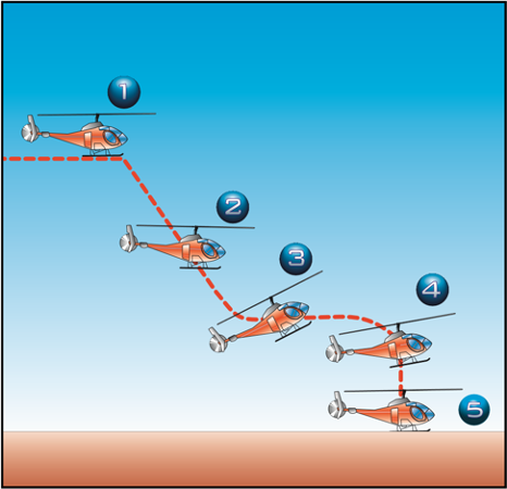
Figure 11-1. Straight-in autorotation.
and leads to “chasing the r.p.m.” Avoid looking straight down in front of the aircraft. Continually cross-check attitude, trim, rotor r.p.m., and airspeed.
At approximately 40 to 100 feet above the surface, or at the altitude recommended by the manufacturer (posi-tion 3), begin the flare with aft cyclic control to reduce forward airspeed and decrease the rate of descent.
Maintain heading with the antitorque pedals. Care must be taken in the execution of the flare so that the cyclic control is not moved rearward so abruptly as to cause the helicopter to climb, nor should it be moved so slowly as to not arrest the descent, which may allow the helicopter to settle so rapidly that the tail rotor strikes the ground. When forward motion decreases to the desired groundspeed, which is usually the slowest possible speed (position 4), move the cyclic control forward to place the helicopter in the proper attitude for landing.
The altitude at this time should be approximately 8 to 15 feet AGL, depending on the altitude recommended by the manufacturer. Extreme caution should be used to avoid an excessive nose high and tail low attitude below 10 feet. At this point, if a full touchdown landing is to be made, allow the helicopter to descend vertically (position 5). Increase collective pitch, as necessary, to check the descent and cushion the landing. Additional antitorque pedal is required to maintain heading as collective pitch is raised due to the reduction in rotor r.p.m. and the resulting reduced effect of the tail rotor.
Touch down in a level flight attitude.
A power recovery can be made during training in lieu of a full touchdown landing. Refer to the section on power recoveries for the correct technique.
After touchdown and after the helicopter has come to a complete stop, lower the collective pitch to the full-down position. Do not try to stop the forward ground run with aft cyclic, as the main rotor blades can strike the tail boom. Rather, by lowering the collective slightly during the ground run, more weight is placed on the undercarriage, slowing the helicopter.
COMMON ERRORS
- Failing to use sufficient antitorque pedal when power is reduced.
- Lowering the nose too abruptly when power is reduced, thus placing the helicopter in a dive.
- Failing to maintain proper rotor r.p.m. during the descent.
- Application of up-collective pitch at an excessive altitude resulting in a hard landing, loss of heading control, and possible damage to the tail rotor and to the main rotor blade stops.
- Failing to level the helicopter.
POWER RECOVERY FROM PRACTICE
AUTOROTATION
A power recovery is used to terminate practice autorotations at a point prior to actual touchdown.
After the power recovery, a landing can be made or a go-around initiated.
TECHNIQUE
At approximately 8 to 15 feet above the ground, depending upon the helicopter being used, begin to level the helicopter with forward cyclic control. Avoid excessive nose high, tail low attitude below 10 feet.
Just prior to achieving level attitude, with the nose still slightly up, coordinate upward collective pitch control with an increase in the throttle to join the needles at operating r.p.m. The throttle and collective pitch must be coordinated properly. If the throttle is increased too fast or too much, an engine overspeed can occur; if throttle is increased too slowly or too little in proportion to the increase in collective pitch, a loss of rotor r.p.m. results. Use sufficient collective pitch to stop the descent and coordinate proper antitorque pedal pressure to maintain heading. When a landing is to be made following the power recovery, bring the helicopter to a hover at normal hovering altitude and then descend to a landing.
If a go-around is to be made, the cyclic control should be moved forward to resume forward flight. In transitioning from a practice autorotation to a go-around, exercise care to avoid an altitude-airspeed combination that would place the helicopter in an unsafe area of its height-velocity diagram.
COMMON ERRORS
- Initiating recovery too late, requiring a rapid application of controls, resulting in overcontrolling.
- Failing to obtain and maintain a level attitude near the surface.
- Failing to coordinate throttle and collective pitch properly, resulting in either an engine overspeed or a loss of r.p.m.
- Failing to coordinate proper antitorque pedal with the increase in power
AUTOROTATIONS WITH TURNS
A turn, or a series of turns, can be made during an autorotation in order to land into the wind or avoid obstacles. The turn is usually made early so that the remainder of the autorotation is the same as a straight in autorotation. The most common types are 90° and 180° autorotations. The technique below describes a
180° autorotation.
TECHNIQUE
Establish the aircraft on downwind at recommended airspeed at 700 feet AGL, parallel to the touchdown area.
In a no wind or headwind condition, establish the ground track approximately 200 feet away from the touchdown point. If a strong crosswind exists, it will be necessary to move your downwind leg closer or farther out. When abeam the intended touchdown point, reduce collective, and then split the needles. Apply proper antitorque pedal and cyclic to maintain proper attitude.
Cross check attitude, trim, rotor r.p.m., and airspeed.
After the descent and airspeed is established, roll into a 180° turn. For training, you should initially roll into a bank of a least 30°, but no more than 40°. Check your airspeed and rotor r.p.m. Throughout the turn, it is important to maintain the proper airspeed and keep the aircraft in trim. Changes in the aircraft’s attitude and the angle of bank cause a corresponding change in rotor r.p.m. Adjust the collective, as necessary, in the turn to maintain rotor r.p.m. in the green arc.
At the 90° point, check the progress of your turn by glancing toward your landing area. Plan the second 90 degrees of turn to roll out on the centerline. If you are too close, decrease the bank angle; if too far out, increase the bank angle. Keep the helicopter in trim with anti-torque pedals.
The turn should be completed and the helicopter aligned with the intended touchdown area prior to passing through 100 feet AGL. If the collective pitch was increased to control the r.p.m., it may have to be lowered on roll out to prevent a decay in r.p.m. Make an immediate power recovery if the aircraft is not aligned with the touchdown point, and if the rotor r.p.m. and/or airspeed is not within proper limits.
From this point, complete the procedure as if it were a straight-in autorotation.
POWER FAILURE IN A HOVER
Power failures in a hover, also called hovering autoro-tations, are practiced so that you automatically make the correct response when confronted with engine stoppage or certain other emergencies while hovering.
The techniques discussed in this section refer to helicopters with a counter-clockwise rotor system and an antitorque rotor.
TECHNIQUE
To practice hovering autorotations, establish a normal hovering altitude for the particular helicopter being used, considering load and atmospheric conditions.
Keep the helicopter headed into the wind and hold maximum allowable r.p.m.
To simulate a power failure, firmly roll the throttle into the spring loaded override position, if applicable. This disengages the driving force of the engine from the rotor, thus eliminating torque effect. As the throttle is closed, apply proper antitorque pedal to maintain head-ing. Usually, a slight amount of right cyclic control is necessary to keep the helicopter from drifting to the left, to compensate for the loss of tail rotor thrust.
However, use cyclic control, as required, to ensure a vertical descent and a level attitude. Leave the collective pitch where it is on entry.
Helicopters with low inertia rotor systems will begin to settle immediately. Keep a level attitude and ensure a vertical descent with cyclic control while maintaining heading with the pedals. At approximately 1 foot above the surface, apply upward collective pitch control, as necessary, to slow the descent and cushion the landing.
Usually the full amount of collective pitch is required.
As upward collective pitch control is applied, the throttle has to be held in the closed position to prevent the rotor from re-engaging.
Helicopters with high inertia rotor systems will maintain altitude momentarily after the throttle is closed. Then, as the rotor r.p.m. decreases, the helicopter starts to settle.
When the helicopter has settled to approximately 1 foot above the surface, apply upward collective pitch control while holding the throttle in the closed position to slow the descent and cushion the landing. The timing of collective pitch control application, and the rate at which it is applied, depends upon the particular helicopter being used, its gross weight, and the existing atmospheric con-ditions. Cyclic control is used to maintain a level attitude and to ensure a vertical descent. Maintain heading with antitorque pedals.
When the weight of the helicopter is entirely on the skids, cease the application of upward collective. When the helicopter has come to a complete stop, lower the collective pitch to the full down position.
The timing of the collective pitch is a most important consideration. If it is applied too soon, the remaining r.p.m. may not be sufficient to make a soft landing. On the other hand, if collective pitch control is applied too late, surface contact may be made before sufficient blade pitch is available to cushion the landing.
COMMON ERRORS
- Failing to use sufficient proper antitorque pedal when power is reduced.
- Failing to stop all sideward or backward movement prior to touchdown.
- Failing to apply up-collective pitch properly, resulting in a hard touchdown.
- Failing to touch down in a level attitude.
- Not rolling the throttle completely to idle.
HEIGHT/VELOCITY DIAGRAM
A height/velocity (H/V) diagram, published by the manufacturer for each model of helicopter, depicts the critical combinations of airspeed and altitude should an engine failure occur. Operating at the altitudes and airspeeds shown within the crosshatched or shaded areas of the H/V diagram may not allow enough time for the critical transition from powered flight to autorotation.
(Figure 11-2]
An engine failure in a climb after takeoff occurring in section A of the diagram is most critical. During a climb, a helicopter is operating at higher power settings and blade angle of attack. An engine failure at this point causes a rapid rotor r.p.m. decay because the upward movement of the helicopter must be stopped, then a descent established in order to drive the rotor. Time is also needed to stabilize, then increase the r.p.m. to the normal operating range. The rate of descent must reach a value that is normal for the airspeed at the moment.
Since altitude is insufficient for this sequence, you end up with decaying r.p.m., an increasing sink rate, no deceleration lift, little translational lift, and little response to the application of collective pitch to cushion the landing.
It should be noted that, once a steady state autorotation has been established, the H/V diagram no longer applies. An engine failure while descending through section A of the diagram, is less critical, provided a safe landing area is available.

Figure 11-2. By carefully studying the height/velocity diagram, you will be able to avoid the combinations of altitude and airspeed that may not allow you sufficient time or altitude to enter a stabilized autorotative descent. You might want to refer to this diagram during the remainder of the discussion on the height/velocity diagram.
You should avoid the low altitude, high airspeed portion of the diagram (section B), because your recognition of an engine failure will most likely coincide with, or shortly occur after, ground contact. Even if you detect an engine failure, there may not be sufficient time to rotate the helicopter from a nose low, high airspeed attitude to one suitable for slowing, then landing. Additionally, the altitude loss that occurs during recognition of engine failure and rotation to a landing attitude, may not leave enough altitude to prevent the tail skid from hitting the ground during the landing maneuver.
Basically, if the helicopter represented by this H/V diagram is above 445 feet AGL, you have enough time and altitude to enter a steady state autorotation, regardless of your airspeed. If the helicopter is hovering at 5 feet AGL (or less) in normal conditions and the engine fails, a safe hovering autorotation can be made. Between approximately 5 feet and 445 feet AGL, however, the transition to autorotation depends on the altitude and airspeed of the helicopter. Therefore, you should always be familiar with the height/velocity diagram for the particular model of helicopter you are flying.
THE EFFECT OF WEIGHT VERSUS DENSITY ALTITUDE
The height/velocity diagram depicts altitude and airspeed situations from which a successful autorotation
can be made. The time required, and therefore, altitude necessary to attain a steady state autorotative descent, is dependent on the weight of the helicopter and the density altitude. For this reason, the H/V diagram for some helicopter models is valid only when the helicopter is operated in accordance with the gross weight vs. density altitude chart. Where appropriate, this chart is found in the rotorcraft flight manual for the particular helicopter. [Figure 11-3]

Figure 11-3. Assuming a density altitude of 5,500 feet, the height/velocity diagram in figure 11-2 would be valid up to a gross weight of approximately 1,700 pounds. This is found by entering the graph at a density altitude of 5,500 feet (point A), then moving horizontally to the solid line (point B). Moving vertically to the bottom of the graph (point C), you find that with the existing density altitude, the maximum gross weight under which the height/velocity diagram is applicable is 1,700 pounds.
The gross weight vs. density altitude chart is not intended as a restriction to gross weight, but as an advisory to the autorotative capability of the helicopter during takeoff and climb. You must realize, however, that at gross weights above those recommended by the gross weight vs. density altitude chart, the H/V diagram is not restrictive enough.
VORTEX RING STATE (SETTLING WITH POWER)
Vortex ring state describes an aerodynamic condition where a helicopter may be in a vertical descent with up to maximum power applied, and little or no cyclic authority. The term “settling with power” comes from the fact that helicopter keeps settling even though full engine power is applied.
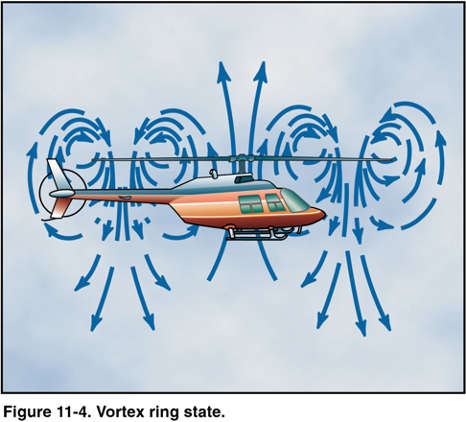
In a normal out-of-ground-effect hover, the helicopter is able to remain stationary by propelling a large mass of air down through the main rotor. Some of the air is recirculated near the tips of the blades, curling up from the bottom of the rotor system and rejoining the air entering the rotor from the top. This phenomenon is common to all airfoils and is known as tip vortices. Tip vortices consume engine power but produce no useful lift. As long as the tip vortices are small, their only effect is a small loss in rotor efficiency. However, when the helicopter begins to descend vertically, it settles into its own downwash, which greatly enlarges the tip vortices. In this vortex ring state, most of the power developed by the engine is wasted in accelerating the air in a doughnut pattern around the rotor.
In addition, the helicopter may descend at a rate that exceeds the normal downward induced-flow rate of the inner blade sections. As a result, the airflow of the inner blade sections is upward relative to the disc. This produces a secondary vortex ring in addition to the normal tip-vortices. The secondary vortex ring is generated about the point on the blade where the airflow changes from up to down. The result is an unsteady turbulent flow over a large area of the disc. Rotor efficiency is lost even though power is still being supplied from the engine. (Figure 11-4]
A fully developed vortex ring state is characterized by an unstable condition where the helicopter experiences uncommanded pitch and roll oscillations, has little or no cyclic authority, and achieves a descent rate, which, if allowed to develop, may approach 6,000 feet per minute. It is accompanied by increased levels of vibration.
A vortex ring state may be entered during any maneuver that places the main rotor in a condition of high upflow and low forward airspeed. This condition is sometimes seen during quick-stop type maneuvers or during recoveries from autorotations. The following combination of conditions are likely to cause settling in a vortex ring state:
- A vertical or nearly vertical descent of at least
300 feet per minute. (Actual critical rate depends on the gross weight, r.p.m., density altitude, and other pertinent factors.) - The rotor system must be using some of the available engine power (from 20 to 100 percent).
- The horizontal velocity must be slower than effective translational lift.
Some of the situations that are conducive to a settling with power condition are: attempting to hover out of ground effect at altitudes above the hovering ceiling of the helicopter; attempting to hover out of ground effect without maintaining precise altitude control; or downwind and steep power approaches in which airspeed is permitted to drop to nearly zero.
When recovering from a settling with power condition, the tendency on the part of the pilot is to first try to stop the descent by increasing collective pitch. However, this only results in increasing the stalled area of the rotor, thus increasing the rate of descent. Since inboard portions of the blades are stalled, cyclic control is limited. Recovery is accomplished by increasing forward speed, and/or partially lowering collective pitch. In a fully developed vortex ring state, the only recovery may be to enter autorotation to break the vortex ring state. When cyclic authority is regained, you can then increase forward airspeed.
For settling with power demonstrations and training in recognition of vortex ring state conditions, all maneuvers should be performed at an elevation of at least 1,500 feet AGL.
To enter the maneuver, reduce power below hover power. Hold altitude with aft cyclic until the airspeed approaches 20 knots. Then allow the sink rate to increase to 300 feet per minute or more as the attitude is adjusted to obtain an airspeed of less than 10 knots. When the aircraft begins to shudder, the application of additional up collective increases the vibration and sink rate.
Recovery should be initiated at the first sign of vortex ring state by applying forward cyclic to increase airspeed and simultaneously reducing collective.
The recovery is complete when the aircraft passes through effective translational lift and a normal climb is established.
RETREATING BLADE STALL
In forward flight, the relative airflow through the main rotor disc is different on the advancing and retreating side. The relative airflow over the advancing side is higher due to the forward speed of the helicopter, while the relative airflow on the retreating side is lower. This dissymmetry of lift increases as forward speed increases.
To generate the same amount of lift across the rotor disc, the advancing blade flaps up while the retreating blade flaps down. This causes the angle of attack to decrease on the advancing blade, which reduces lift, and increase on the retreating blade, which increases lift. As the forward speed increases, at some point the low blade speed on the retreating blade, together with its high angle of attack, causes a loss of lift (stall).
Retreating blade stall is a major factor in limiting a helicopter’s top forward speed (VNE) and can be felt developing by a low frequency vibration, pitching up of the nose, and a roll in the direction of the retreating blade. High weight, low rotor r.p.m., high density altitude, turbulence and/or steep, abrupt turns are all conducive to retreating blade stall at high forward airspeeds. As altitude is increased, higher blade angles are required to maintain lift at a given airspeed. Thus, retreating blade stall is encountered at a lower forward airspeed at altitude.
Most manufacturers publish charts and graphs showing a VNe decrease with altitude.
When recovering from a retreating blade stall condi-tion, moving the cyclic aft only worsens the stall as aft cyclic produces a flare effect, thus increasing angles of attack. Pushing forward on the cyclic also deepens the stall as the angle of attack on the retreating blade is increased. Correct recovery from retreating blade stall requires the collective to be lowered first, which reduces blade angles and thus angle of attack. Aft cyclic can then be used to slow the helicopter.
GROUND RESONANCE
Ground resonance is an aerodynamic phenomenon associated with fully-articulated rotor systems. It develops when the rotor blades move out of phase with each other and cause the rotor disc to become unbalanced. This condition can cause a helicopter to self-destruct in a matter of seconds. However, for this condition to occur, the helicopter must be in contact with the ground.
If you allow your helicopter to touch down firmly on one corner (wheel type landing gear is most conducive for this the shock is transmitted to the main rotor system. This may cause the blades to move out of their normal relationship with each other. This movement occurs along the drag hinge. (Figure 11-5]
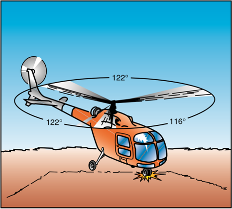
Figure 11-5. Hard contact with the ground can send a shock wave to the main rotor head, resulting in the blades of a three-bladed rotor system moving from their normal 120° relationship to each other. This could result in something like 122°, 122°, and 116° between blades. When one of the other landing gear strikes the surface, the unbalanced condition could be further aggravated.
If the r.p.m. is low, the corrective action to stop ground resonance is to close the throttle immediately and fully lower the collective to place the blades in low pitch. If the r.p.m. is in the normal operating range, you should fly the helicopter off the ground, and allow the blades to automatically realign themselves. You can then make a normal touchdown. If you lift off and allow the helicopter to firmly re-contact the surface before the blades are realigned, a second shock could move the blades again and aggravate the already unbalanced condition. This could lead to a violent, uncontrollable oscillation.
This situation does not occur in rigid or semirigid rotor systems, because there is no drag hinge. In addition, skid type landing gear are not as prone to ground resonance as wheel type gear.
DYNAMIC ROLLOVER
A helicopter is susceptible to a lateral rolling tendency, called dynamic rollover, when lifting off the surface.
For dynamic rollover to occur, some factor has to first cause the helicopter to roll or pivot around a skid, or landing gear wheel, until its critical rollover angle is reached. Then, beyond this point, main rotor thrust continues the roll and recovery is impossible. If the critical rollover angle is exceeded, the helicopter rolls on its side regardless of the cyclic corrections made.
Dynamic rollover begins when the helicopter starts to pivot around its skid or wheel. This can occur for a variety of reasons, including the failure to remove a tiedown or skid securing device, or if the skid or wheel contacts a fixed object while hovering sideward, or if the gear is stuck in ice, soft asphalt, or mud. Dynamic rollover may also occur if you do not use the proper landing or takeoff technique or while performing slope operations. Whatever the cause, if the gear or skid becomes a pivot point, dynamic rollover is possible if you do not use the proper corrective technique.
Once started, dynamic rollover cannot be stopped by application of opposite cyclic control alone. For exam-ple, the right skid contacts an object and becomes the pivot point while the helicopter starts rolling to the right. Even with full left cyclic applied, the main rotor thrust vector and its moment follows the aircraft as it continues rolling to the right. Quickly applying down collective is the most effective way to stop dynamic rollover from developing. Dynamic rollover can occur in both skid and wheel equipped helicopters, and all types of rotor systems.
CRITICAL CONDITIONS
Certain conditions reduce the critical rollover angle, thus increasing the possibility for dynamic rollover and reducing the chance for recovery. The rate of rolling motion is also a consideration, because as the roll rate increases, the critical rollover angle at which recovery is still possible, is reduced. Other critical conditions include operating at high gross weights with thrust (lift) approximately equal to the weight.
Refer to figure 11-6. The following conditions are most critical for helicopters with counter-clockwise rotor rotation:
- right lateral center of gravity.
- right side skid/wheel down, since translating tendency adds to the rollover force.

Figure 11-6. Forces acting on a helicopter with right skid on the ground.
- crosswinds from the left.
- left yaw inputs.
For helicopters with clockwise rotor rotation, the opposite would be true.
CYCLIC TRIM
When maneuvering with one skid or wheel on the ground, care must be taken to keep the helicopter cyclic control properly trimmed. For example, if a slow takeoff is attempted and the cyclic is not positioned and trimmed to account for translating tendency, the critical recovery angle may be exceeded in less than two sec-onds. Control can be maintained if you maintain proper cyclic position and trim, and not allow the helicopter’s roll and pitch rates to become too great. You should fly your helicopter into the air smoothly while keeping movements of pitch, roll, and yaw small, and not allow any untrimmed cyclic pressures.
NORMAL TAKEOFFS AND LANDINGS
Dynamic rollover is possible even during normal takeoffs and landings on relative level ground, if one wheel or skid is on the ground and thrust (lift) is approximately equal to the weight of the helicopter. If the takeoff or landing is not performed properly, a roll rate could develop around the wheel or skid that is on the ground. When taking off or landing, perform the maneuver smoothly and trim the cyclic so that no pitch or roll movement rates build up, especially the roll rate.
If the bank angle starts to increase to an angle of approximately 5 to 8°, and full corrective cyclic does not reduce the angle, the collective should be reduced to diminish the unstable rolling condition.
SLOPE TAKEOFFS AND LANDINGS
During slope operations, excessive application of cyclic control into the slope, together with excessive collective pitch control, can result in the downslope skid rising sufficiently to exceed lateral cyclic control limits, and an upslope rolling motion can occur. [Figure 11-7]

Figure 11-7. Upslope rolling motion.
When performing slope takeoff and landing maneu-vers, follow the published procedures and keep the roll rates small. Slowly raise the downslope skid or wheel to bring the helicopter level, and then lift off. During landing, first touch down on the upslope skid or wheel, then slowly lower the downslope skid or wheel using combined movements of cyclic and collective. If the helicopter rolls approximately 5 to 8° to the upslope side, decrease collective to correct the bank angle and return to level attitude, then start the landing procedure again.
USE OF COLLECTIVE
The collective is more effective in controlling the rolling motion than lateral cyclic, because it reduces the main rotor thrust (lift). A smooth, moderate collective reduc-tion, at a rate less than approximately full up to full down in two seconds, is adequate to stop the rolling motion.
Take care, however, not to dump collective at too high a rate, as this may cause a main rotor blade to strike the fuselage. Additionally, if the helicopter is on a slope and the roll starts to the upslope side, reducing collective too fast may create a high roll rate in the opposite direction.
When the upslope skid/wheel hits the ground, the dynamics of the motion can cause the helicopter to bounce off the upslope skid/wheel, and the inertia can cause the helicopter to roll about the downslope ground contact point and over on its side. [Figure 11-8]
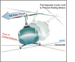
Figure 11-8. Downslope rolling motion.
The collective should not be pulled suddenly to get air-borne, as a large and abrupt rolling moment in the opposite direction could occur. Excessive application of collective can result in the upslope skid rising sufficiently to exceed lateral cyclic control limits. This movement may be uncontrollable. If the helicopter
develops a roll rate with one skid/wheel on the ground, the helicopter can roll over on its side.
PRECAUTIONS
The following lists several areas to help you avoid dynamic rollover.
- Always practice hovering autorotations into the wind, but never when the wind is gusty or over
10 knots. - When hovering close to fences, sprinklers, bushes, runway/taxi lights, or other obstacles that could catch a skid, use extreme caution.
- Always use a two-step liftoff. Pull in just enough collective pitch control to be light on the skids and feel for equilibrium, then gently lift the helicopter into the air.
- When practicing hovering maneuvers close to the ground, make sure you hover high enough to have adequate skid clearance with any obsta-cles, especially when practicing sideways or rearward flight.
- When the wind is coming from the upslope direc-tion, less lateral cyclic control will be available.
- Tailwind conditions should be avoided when conducting slope operations.
- When the left skid/wheel is upslope, less lateral cyclic control is available due to the translating tendency of the tail rotor. (This is true for counter-rotating rotor systems)
- If passengers or cargo are loaded or unloaded, the lateral cyclic requirement changes.
- If the helicopter utilizes interconnecting fuel lines that allow fuel to automatically transfer from one side of the helicopter to the other, the gravitational flow of fuel to the downslope tank could change the center of gravity, resulting in a different amount of cyclic control application to obtain the same lateral result.
- Do not allow the cyclic limits to be reached. If the cyclic control limit is reached, further lowering of the collective may cause mast bumping. If this occurs, return to a hover and select a landing point with a lesser degree of slope.
- During a takeoff from a slope, if the upslope skid/wheel starts to leave the ground before the downslope skid/wheel, smoothly and gently lower the collective and check to see if the downslope skid/wheel is caught on something. Under these conditions, vertical ascent is the only acceptable method of liftoff.
- During flight operations on a floating platform, if the platform is pitching/rolling while attempting to land or takeoff, the result could be dynamic rollover.
LOW G CONDITIONS AND MAST BUMPING
For cyclic control, small helicopters depend primarily on tilting the main rotor thrust vector to produce control moments about the aircraft center of gravity (CG), causing the helicopter to roll or pitch in the desired direction. Pushing the cyclic control forward abruptly from either straight-and-level flight or after a climb can put the helicopter into a low G (weightless) flight condition. In forward flight, when a push-over is performed, the angle of attack and thrust of the rotor is reduced, causing a low G or weightless flight condi-tion. During the low G condition, the lateral cyclic has little, if any, effect because the rotor thrust has been reduced. Also, in a counter-clockwise rotor system (a clockwise system would be the reverse), there is no main rotor thrust component to the left to counteract the tail rotor thrust to the right, and since the tail rotor is above the CG, the tail rotor thrust causes the helicopter to roll rapidly to the right, If you attempt to stop the right roll by applying full left cyclic before regaining main rotor thrust, the rotor can exceed its flapping limits and cause structural failure of the rotor shaft due to mast bumping, or it may allow a blade to contact the airframe. [Figure 11-9]
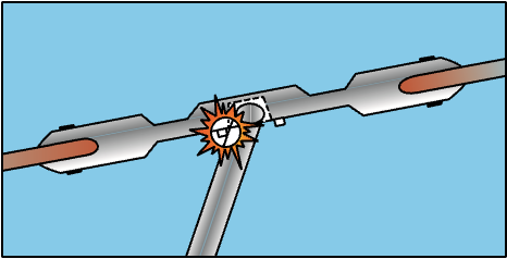
Figure 11-9. In a low G condition, improper corrective action could lead to the main rotor hub contacting the rotor mast. The contact with the mast becomes more violent with each successive flapping motion. This, in turn, creates a greater flapping displacement. The result could be a severely damaged rotor mast, or the main rotor system could separate from the helicopter.
Since a low G condition could have disastrous results, the best way to prevent it from happening is to avoid the conditions where it might occur. This means avoiding turbulence as much as possible. If you do encounter turbulence, slow your forward airspeed and make small control inputs. If turbulence becomes excessive, consider making a precautionary landing. To help prevent turbulence induced inputs, make sure your cyclic arm is properly supported. One way to accomplish this is to brace your arm against your leg. Even if you are not in turbulent conditions, you should avoid abrupt movement of the cyclic and collective.
If you do find yourself in a low G condition, which can be recognized by a feeling of weightlessness and an uncontrolled roll to the right, you should immediately and smoothly apply aft cyclic. Do not attempt to correct the rolling action with lateral cyclic. By applying aft cyclic, you will load the rotor system, which in turn produces thrust. Once thrust is restored, left cyclic control becomes effective, and you can roll the helicopter to a level attitude.
LOW ROTOR RPM AND BLADE STALL
As mentioned earlier, low rotor r.p.m. during an autorotation might result in a less than successful maneuver. However, if you let rotor r.p.m. decay to the point where all the rotor blades stall, the result is usually fatal, especially when it occurs at altitude. The danger of low rotor r.p.m. and blade stall is greatest in small helicopters with low blade inertia. It can occur in a number of ways, such as simply rolling the throttle the wrong way, pulling more collective pitch than power available, or when operating at a high density altitude.
When the rotor r.p.m. drops, the blades try to maintain the same amount of lift by increasing pitch. As the pitch increases, drag increases, which requires more power to keep the blades turning at the proper r.p.m.
When power is no longer available to maintain r.p.m., and therefore lift, the helicopter begins to descend.
This changes the relative wind and further increases the angle of attack. At some point the blades will stall unless r.p.m. is restored. If all blades stall, it is almost impossible to get smooth air flowing across the blades.
Even though there is a safety factor built into most hel-icopters, anytime your rotor r.p.m. falls below the green arc, and you have power, simultaneously add throttle and lower the collective. If you are in forward flight, gently applying aft cyclic loads up the rotor system and helps increase rotor r.p.m. If you are without power, immediately lower the collective and apply aft cyclic.
RECOVERY FROM LOW ROTOR RPM
Under certain conditions of high weight, high tempera-ture, or high density altitude, you might get into a situation where the r.p.m. is low even though you are using maximum throttle. This is usually the result of the main rotor blades having an angle of attack that has created so much drag that engine power is not sufficient to maintain or attain normal operating r.p.m.
If you are in a low r.p.m. situation, the lifting power of the main rotor blades can be greatly diminished. As soon as you detect a low r.p.m. condition, immediately apply additional throttle, if available, while slightly lowering the collective. This reduces main rotor pitch and drag. As the helicopter begins to settle, smoothly raise the collective to stop the descent. At hovering altitude you may have to repeat this technique several times to regain normal operating r.p.m. This technique is sometimes called
“milking the collective.” When operating at altitude, the collective may have to be lowered only once to regain rotor speed. The amount the collective can be lowered depends on altitude. When hovering near the surface, make sure the helicopter does not contact the ground as the collective is lowered.
Since the tail rotor is geared to the main rotor, low main rotor r.p.m. may prevent the tail rotor from producing enough thrust to maintain directional control. If pedal control is lost and the altitude is low enough that a landing can be accomplished before the turning rate increases dangerously, slowly decrease collective pitch, maintain a level attitude with cyclic control, and land.
SYSTEM MALFUNCTIONS
The reliability and dependability record of modern helicopters is very impressive. By following the manufacturer’s recommendations regarding periodic maintenance and inspections, you can eliminate most systems and equipment failures. Most malfunctions or failures can be traced to some error on the part of the pilot; therefore, most emergencies can be averted before they happen. An actual emergency is a rare occurrence.
ANTITORQUE SYSTEM FAILURE
Antitorque failures usually fall into two categories.
One focuses on failure of the power drive portion of the tail rotor system resulting in a complete loss of anti-torque. The other category covers mechanical control failures where the pilot is unable to change or control tail rotor thrust even though the tail rotor may still be providing antitorque thrust.
Tail rotor drive system failures include driveshaft fail-ures, tail rotor gearbox failures, or a complete loss of the tail rotor itself. In any of these cases, the loss of antitorque normally results in an immediate yawing of the helicopter’s nose. The helicopter yaws to the right in a counter-clockwise rotor system and to the left in a clockwise system. This discussion assumes a helicopter with a counter-clockwise rotor system. The severity of the yaw is proportionate to the amount of power being used and the airspeed. An antitorque failure with a high power setting at a low airspeed results in a severe yawing to the right. At low power settings and high airspeeds, the yaw is less severe. High airspeeds tend to streamline the helicopter and keep it from spinning.
If a tail rotor failure occurs, power has to be reduced in order to reduce main rotor torque. The techniques differ depending on whether the helicopter is in flight or in a hover, but will ultimately require an autorotation.
If a complete tail rotor failure occurs while hovering, enter a hovering autorotation by rolling off the throttle. If the failure occurs in forward flight, enter a normal autorotation by lowering the collective and rolling off the throttle. If the helicopter has enough forward airspeed (close to cruising speed) when the failure occurs, and depending on the helicopter design, the vertical stabilizer may provide enough directional control to allow you to maneuver the helicopter to a more desirable landing sight. Some of the yaw may be compensated for by applying slight cyclic control opposite the direction of yaw. This helps in directional control, but also increases drag. Care must be taken not to lose too much forward airspeed because the streamlining effect diminishes as airspeed is reduced. Also, more altitude is required to accelerate to the correct airspeed if an autorotation is entered into at a low airspeed.
A mechanical control failure limits or prevents control of tail rotor thrust and is usually caused by a stuck or broken control rod or cable. While the tail rotor is still producing antitorque thrust, it cannot be controlled by the pilot. The amount of antitorque depends on the position where the controls jam or fail. Once again, the techniques differ depending on the amount of tail rotor thrust, but an autorotation is generally not required.
LANDING-STUCK LEFT PEDAL
Be sure to follow the procedures and techniques outlined in the FAA-approved rotorcraft flight manual for the helicopter you are flying. A stuck left pedal, such as might be experienced during takeoff or climb conditions, results in the helicopter’s nose yawing to the left when power is reduced. Rolling off the throttle and entering an autorotation only makes matters worse. The landing profile for a stuck left pedal is best described as a normal approach to a momentary hover at three to four feet above the surface. Following an analysis, make the landing. If the helicopter is not turning, simply lower the helicopter to the surface. If the helicopter is turning to the right, roll the throttle toward flight idle the amount necessary to stop the turn as you land. If the helicopter is beginning to turn left, you should be able to make the landing prior to the turn rate becoming excessive. However, if the turn rate becomes excessive prior to the landing, simply execute a takeoff and return for another landing.
LANDING-STUCK NEUTRAL OR RIGHT PEDAL
The landing profile for a stuck neutral or a stuck right pedal is a low power approach or descent with a running or roll-on landing. The approach profile can best be described as a steep approach with a flare at the bottom to slow the helicopter. The power should be low enough to establish a left yaw during the descent. The left yaw allows a margin of safety due to the fact that the helicopter will turn to the right when power is applied. This allows the momentary use of power at the bottom of the approach. As you apply power, the helicopter rotates to the right and becomes aligned with the landing area. At this point, roll the throttle to flight idle and make the landing. The momentary use of power helps stop the descent and allows additional time for you to level the helicopter prior to closing the throttle.
If the helicopter is not yawed to the left at the conclusion of the flare, roll the throttle to flight idle and use the collective to cushion the touchdown. As with any running or roll-on landing, use the cyclic to maintain the ground track. This technique results in a longer ground run or roll than if the helicopter was yawed to the left.
UNANTICIPATED YAW / LOSS OF TAIL ROTOR EFFECTIVENESS (LTE)
Unanticipated yaw is the occurrence of an uncom-manded yaw rate that does not subside of its own accord and, which, if not corrected, can result in the loss of helicopter control. This uncommanded yaw rate is referred to as loss of tail rotor effectiveness (LTE) and occurs to the right in helicopters with a counterclockwise rotating main rotor and to the left in helicopters with a clockwise main rotor rotation. Again, this discussion covers a helicopter with a counter-clockwise rotor system and an antitorque rotor.
LTE is not related to an equipment or maintenance malfunction and may occur in all single-rotor helicopters at airspeeds less than 30 knots. It is the result of the tail rotor not providing adequate thrust to maintain directional control, and is usually caused by either certain wind azimuths (directions) while hovering, or by an insufficient tail rotor thrust for a given power setting at higher altitudes.
For any given main rotor torque setting in perfectly steady air, there is an exact amount of tail rotor thrust required to prevent the helicopter from yawing either left or right. This is known as tail rotor trim thrust. In order to maintain a constant heading while hovering, you should maintain tail rotor thrust equal to trim thrust.
The required tail rotor thrust is modified by the effects of the wind. The wind can cause an uncommanded yaw by changing tail rotor effective thrust. Certain relative wind directions are more likely to cause tail rotor thrust variations than others. Flight and wind tunnel tests
have identified three relative wind azimuth regions that can either singularly, or in combination, create an LTE conducive environment. These regions can overlap, and thrust variations may be more pronounced. Also, flight testing has determined that the tail rotor does not actually stall during the period. When operating in these areas at less than 30 knots, pilot workload increases dramatically.
MAIN ROTOR DISC INTERFERENCE (285-315°)
Refer to figure 11-10. Winds at velocities of 10 to 30 knots from the left front cause the main rotor vortex to be blown into the tail rotor by the relative wind. The effect of this main rotor disc vortex causes the tail rotor to operated in an extremely turbulent envi-ronment. During a right turn, the tail rotor experiences a reduction of thrust as it comes into the area of the main rotor disc vortex. The reduction in tail rotor thrust comes from the airflow changes experienced at the tail rotor as the main rotor disc vortex moves across the tail rotor disc. The effect of the main rotor disc vortex initially increases the angle of attack of the tail rotor blades, thus increasing tail rotor thrust. The increase in the angle of attack requires that right pedal pressure be added to reduce tail rotor thrust in order to maintain the same rate of turn. As the main rotor vortex passes the tail rotor, the tail rotor angle of attack is reduced. The reduction in the angle of attack causes a reduction in thrust and a right yaw acceleration begins. This acceleration can be surprising, since you were previously adding right pedal to maintain the right turn rate. This thrust reduction occurs suddenly, and if uncorrected, develops into an uncontrollable rapid rotation about the mast. When operating within this region, be aware that the reduction in tail rotor thrust can happen quite suddenly, and be prepared to react quickly to counter this reduction with additional left pedal input.
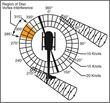
Figure 11-10. Main rotor disc vortex interference.
WEATHERCOCK STABILITY (120-240°)
In this region, the helicopter attempts to weathervane its nose into the relative wind. [Figure 11-11] Unless a resisting pedal input is made, the helicopter starts a slow, uncommanded turn either to the right or left depending upon the wind direction. If the pilot allows a right yaw rate to develop and the tail of the helicopter moves into this region, the yaw rate can accelerate rapidly. In order to avoid the onset of LTE in this downwind condition, it is imperative to maintain positive control of the yaw rate and devote full attention to flying the helicopter.

Figure 11-11. Weathercock stability.
TAIL ROTOR VORTEX RING STATE (210-330°)
Winds within this region cause a tail rotor vortex ring state to develop. [Figure 11-12] The result is a non-uni-form, unsteady flow into the tail rotor. The vortex ring state causes tail rotor thrust variations, which result in yaw deviations. The net effect of the unsteady flow is an oscillation of tail rotor thrust. Rapid and continuous pedal movements are necessary to compensate for the rapid changes in tail rotor thrust when hovering in a left crosswind. Maintaining a precise heading in this region is difficult, but this characteristic presents no significant problem unless corrective action is delayed.
However, high pedal workload, lack of concentration and overcontrolling can all lead to LTE.
When the tail rotor thrust being generated is less than the thrust required, the helicopter yaws to the right.
When hovering in left crosswinds, you must concentrated on smooth pedal coordination and not allow an uncontrolled right yaw to develop. If a right yaw rate is allowed to build, the helicopter can rotate into the wind azimuth region where weathercock stability then accelerates the right turn rate. Pilot workload during a tail rotor vortex ring state is high. Do not allow a right yaw rate to increase.

Figure 11-12. Tail rotor vortex ring state.
LTE AT ALTITUDE
At higher altitudes, where the air is thinner, tail rotor thrust and efficiency is reduced. When operating at high altitudes and high gross weights, especially while hovering, the tail rotor thrust may not be sufficient to maintain directional control and LTE can occur. In this case, the hovering ceiling is limited by tail rotor thrust and not necessarily power available. In these conditions gross weights need to be reduced and/or operations need to be limited to lower density altitudes.
REDUCING THE ONSET OF LTE
To help reduce the onset of loss of tail rotor effective-ness, there are some steps you can follow.
- Maintain maximum power-on rotor r.p.m. If the main rotor r.p.m. is allowed to decrease, the anti-torque thrust available is decreased proportionally.
- Avoid tailwinds below an airspeed of 30 knots. If loss of translational lift occurs, it results in an increased power demand and additional anti-torque pressures.
- Avoid out of ground effect (OGE) operations and high power demand situations below an airspeed of 30 knots.
- Be especially aware of wind direction and velocity when hovering in winds of about 8-12 knots. There are no strong indicators that translational lift has been reduced. A loss of translational lift results in an unexpected high power demand and an increased antitorque requirement.
- Be aware that if a considerable amount of left pedal is being maintained, a sufficient amount of left pedal may not be available to counteract an unanticipated right yaw.
- Be alert to changing wind conditions, which may be experienced when flying along ridge lines and around buildings.
RECOVERY TECHNIQUE
If a sudden unanticipated right yaw occurs, the following recovery technique should be performed. Apply full left pedal while simultaneously moving cyclic control forward to increase speed. If altitude permits, reduce power. As recovery is effected, adjust controls for normal forward flight.
Collective pitch reduction aids in arresting the yaw rate but may cause an excessive rate of descent. Any large, rapid increase in collective to prevent ground or obstacle contact may further increase the yaw rate and decrease rotor r.p.m. The decision to reduce collective must be based on your assessment of the altitude available for recovery.
If the rotation cannot be stopped and ground contact is imminent, an autorotation may be the best course of action. Maintain full left pedal until the rotation stops, then adjust to maintain heading.
MAIN DRIVE SHAFT FAILURE
The main drive shaft, located between the engine and the main rotor gearbox, transmits engine power to the main rotor gearbox. In some helicopters, particularly those with piston engines, a drive belt is used instead of a drive shaft. A failure of the drive shaft or belt has the same effect as an engine failure, because power is no longer provided to the main rotor, and an autorotation has to be initiated. There are a few differences, however, that need to be taken into consideration. If the drive shaft or belt breaks, the lack of any load on the engine results in an overspeed. In this case, the throttle must be closed in order to prevent any further damage.
In some helicopters, the tail rotor drive system continues to be powered by the engine even if the main drive shaft breaks. In this case, when the engine unloads, a tail rotor overspeed can result. If this hap-pens, close the throttle immediately and enter an autorotation.
HYDRAULIC FAILURES
Most helicopters, other than smaller piston powered helicopters, incorporate the use of hydraulic actuators to overcome high control forces. A hydraulic system consists of actuators, also called servos, on each flight control; a pump, which is usually driven by the main rotor gearbox; and a reservoir to store the hydraulic fluid. A switch in the cockpit can turn the system off, although it is left on under normal conditions. A pressure indicator in the cockpit may be installed to monitor the system.
An impending hydraulic failure can be recognized by a grinding or howling noise from the pump or actuators, increased control forces and feedback, and limited control movement. The corrective action required is stated in detail in the appropriate rotorcraft flight manual. However, in most cases, airspeed needs to be reduced in order to reduce control forces. The hydraulic switch and circuit breaker should be checked and recycled. If hydraulic power is not restored, make a shallow approach to a running or roll-on landing. This technique is used because it requires less control force and pilot workload. Additionally, the hydraulic system should be disabled, by either pulling the circuit breaker and/or placing the switch in the off position. The reason for this is to prevent an inadvertent restoration of hydraulic power, which may lead to overcontrolling near the ground.
In those helicopters where the control forces are so high that they cannot be moved without hydraulic assistance, two or more independent hydraulic systems may be installed. Some helicopters use hydraulic accumulators to store pressure that can be used for a short time while in an emergency if the hydraulic pump fails.
This gives you enough time to land the helicopter with normal control.
GOVERNOR FAILURE
Governors automatically adjust engine power to maintain rotor r.p.m. when the collective pitch is changed. If the governor fails, any change in collective pitch requires you to manually adjust the throttle to maintain correct r.p.m. In the event of a high side governor failure, the engine and rotor r.p.m. try to increase above the normal range. If the r.p.m. cannot be reduced and controlled with the throttle, close the throttle and enter an autorotation. If the governor fails on the low side, normal r.p.m. may not be attainable, even if the throttle is manually controlled. In this case, the collective has to be lowered to maintain r.p.m. A running or roll-on landing may be performed if the engine can maintain sufficient rotor r.p.m. If there is insufficient power, enter an autorotation.
ABNORMAL VIBRATIONS
With the many rotating parts found in helicopters, some vibration is inherent. You need to understand the cause and effect of helicopter vibrations because abnormal vibrations cause premature component wear and may even result in structural failure. With experience, you learn what vibrations are normal versus those that are abnormal and can then decide whether continued flight is safe or not. Helicopter vibrations are categorized into low, medium, or high frequency.
LOW FREQUENCY VIBRATIONS
Low frequency vibrations (100-500 cycles per minute) usually originate from the main rotor system. The vibration may be felt through the controls, the airframe, or a combination of both. Furthermore, the vibration may have a definite direction of push or thrust. It may be vertical, lateral, horizontal, or even a combination.
Normally, the direction of the vibration can be determined by concentrating on the feel of the vibration, which may push you up and down, backwards and forwards, or from side to side. The direction of the vibration and whether it is felt in the controls or the airframe is an important means for the mechanic to troubleshoot the source. Some possible causes could be that the main rotor blades are out of track or balance, damaged blades, worn bearings, dampers out of adjustment, or worn parts.
MEDIUM AND HIGH FREQUENCY VIBRATIONS
Medium frequency vibrations (1,000 – 2,000 cycles per minute and high frequency vibrations (2,000 cycles per minute or higher) are normally associated with out-of-balance components that rotate at a high r.p.m., such as the tail rotor, engine, cooling fans, and components of the drive train, including transmissions, drive shafts, bearings, pulleys, and belts. Most tail rotor vibrations can be felt through the tail rotor pedals as long as there are no hydraulic actuators, which usually dampen out the vibration. Any imbalance in the tail rotor system is very harmful, as it can cause cracks to develop and rivets to work loose. Piston engines usually produce a normal amount of high frequency vibration, which is aggravated by engine malfunctions such as spark plug fouling, incorrect magneto timing, carburetor icing and/or incorrect fuel/air mixture. Vibrations in turbine engines are often difficult to detect as these engines operate at a very high r.p.m.
TRACKING AND BALANCE
Modern equipment used for tracking and balancing the main and tail rotor blades can also be used to detect other vibrations in the helicopter. These systems use accelerometers mounted around the helicopter to detect the direction, frequency, and intensity of the vibration.
The built-in software can then analyze the information, pinpoint the origin of the vibration, and suggest the corrective action.
FLIGHT DIVERSION
There will probably come a time in your flight career when you will not be able to make it to your destination.
This can be the result of unpredictable weather conditions, a system malfunction, or poor preflight planning. In any case, you will need to be able to safely and efficiently divert to an alternate destination. Before any cross-country flight, check the charts for airports or suitable landing areas along or near your route of flight. Also, check for navaids that can be used during a diversion.
Computing course, time, speed, and distance information in flight requires the same computations used during preflight planning. However, because of the limited cockpit space, and because you must divide your attention between flying the helicopter, making calculations, and scanning for other aircraft, you should take advantage of all possible shortcuts and rule-of-thumb computations.
When in flight, it is rarely practical to actually plot a course on a sectional chart and mark checkpoints and distances. Furthermore, because an alternate airport is usually not very far from your original course, actual plotting is seldom necessary.
A course to an alternate can be measured accurately with a protractor or plotter, but can also be measured with reasonable accuracy using a straightedge and the compass rose depicted around VOR stations. This approximation can be made on the basis of a radial from a nearby VOR or an airway that closely parallels the course to your alternate. However, you must remember that the magnetic heading associated with a VOR radial or printed airway is outbound from the station. To find the course TO the station, it may be necessary to determine the reciprocal of the indicated heading.
Distances can be determined by using a plotter, or by placing a finger or piece of paper between the two and then measuring the approximate distance on the mileage scale at the bottom of the chart.
Before changing course to proceed to an alternate, you should first consider the relative distance and route of flight to all suitable alternates. In addition, you should consider the type of terrain along the route. If circumstances warrant, and your helicopter is equipped with navigational equipment, it is typically easier to navigate to an alternate airport that has a VOR or NDB facility on the field.
After you select the most appropriate alternate, approximate the magnetic course to the alternate using a compass rose or airway on the sectional chart. If time permits, try to start the diversion over a prominent ground feature. However, in an emergency, divert promptly toward your alternate. To complete all plotting, measuring, and computations involved before diverting to the alternate may only aggravate an actual emergency.
Once established on course, note the time, and then use the winds aloft nearest to your diversion point to calculate a heading and groundspeed. Once you have calculated your groundspeed, determine a new arrival time and fuel consumption.
You must give priority to flying the helicopter while dividing your attention between navigation and planning. When determining an altitude to use while diverting, you should consider cloud heights, winds, terrain, and radio reception.
LOST PROCEDURES
Getting lost in an aircraft is a potentially dangerous situation especially when low on fuel. Helicopters have an advantage over airplanes, as they can land almost anywhere before they run out of fuel.
If you are lost, there are some good common sense procedures to follow. If you are nowhere near or cannot see a town or city, the first thing you should do is climb.
An increase in altitude increases radio and navigation reception range, and also increases radar coverage. If you are flying near a town or city, you may be able to read the name of the town on a water tower or even land to ask directions.
If your helicopter has a navigational radio, such as a VOR or ADF receiver, you can possibly determine your position by plotting your azimuth from two or more navigational facilities. If GPS is installed, or you have a portable aviation GPS on board, you can use it to determine your position and the location of the nearest airport.
Communicate with any available facility using frequencies shown on the sectional chart. If you are able to communicate with a controller, you may be offered radar vectors. Other facilities may offer direction finding (DF) assistance. To use this procedure, the controller will request you to hold down your transmit button for a few seconds and then release it. The controller may ask you to change directions a few times and repeat the transmit procedure. This gives the controller enough information to plot your position and then give you vectors to a suitable landing sight. If your situation becomes threatening, you can transmit your problems on the emergency frequency 121.5 MHZ and set your transponder to 7700. Most facilities, and even airliners, monitor the emergency frequency.
EMERGENCY EQUIPMENT AND SURVIVAL GEAR
Both Canada and Alaska require pilots to carry survival gear. However, it is good common sense that any time you are flying over rugged and desolated terrain, consider carrying survival gear. Depending on the size and storage capacity of your helicopter, the following are some suggested items:
Food that is not subject to deterioration due to heat or cold. There should be at least 10,000 calo
ries for each person on board, and it should be stored in a sealed waterproof container. It should have been inspected by the pilot or his representative within the previous six months, and bear a label verifying the amount and satisfactory condition of the contents.
- A supply of water.
- Cooking utensils.
- Matches in a waterproof container.
- A portable compass.
- An ax at least 2.5 pounds with a handle not less than 28 inches in length.
- A flexible saw blade or equivalent cutting tool.
- 30 feet of snare wire and instructions for use.
- Fishing equipment, including still-fishing bait and gill net with not more than a two inch mesh.
- Mosquito nets or netting and insect repellent sufficient to meet the needs of all persons aboard, when operating in areas where insects are likely to be hazardous.
- A signaling mirror.
- At least three pyrotechnic distress signals.
- A sharp, quality jackknife or hunting knife.
- A suitable survival instruction manual.
- Flashlight with spare bulbs and batteries.
- Portable ELT with spare batteries.
Additional items when there are no trees:
- Stove with fuel or a self-contained means of providing heat for cooking.
- Tent(s) to accommodate everyone on board.
Additional items for winter operations:
- Winter sleeping bags for all persons when the temperature is expected to be below 7°C.
- Two pairs of snow shoes.
- Spare ax handle.
- Honing stone or file.
- Ice chisel.
- Snow knife or saw knife.


