Note: In this chapter, it is assumed that the helicopter has a counterclockwise main rotor blade rotation as viewed from above. If flying a helicopter with a clockwise rotation, you will need to reverse left and right references, particularly in the areas of rotor blade pitch change, anti- torque pedal movement, and tail rotor thrust.
There are four basic controls used during flight. They are the collective pitch control, the throttle, the cyclic pitch control, and the antitorque pedals.
Collective pitch control
The collective pitch control, located on the left side of the pilot’s seat, changes the pitch angle of all main rotor blades simultaneously, or collectively, as the name implies. As the collective pitch control is raised, there is a simultaneous and equal increase in pitch angle of all main rotor blades; as it is lowered, there is a simultaneous and equal decrease in pitch angle. This is done through a series of mechanical linkages and the amount of movement in the collective lever determines the amount of blade pitch change. [Figure 4-1] An adjustable friction control helps prevent inadvertent collective pitch movement.
Changing the pitch angle on the blades changes the angle of attack on each blade. With a change in angle of attack comes a change in drag, which affects the speed or r.p.m. of the main rotor. As the pitch angle increases, angle of attack increases, drag increases, and rotor r.p.m. decreases. Decreasing pitch angle decreases both angle of attack and drag, while rotor r.p.m. increases. In order to maintain a constant rotor r.p.m., which is essential in helicopter operations, a proportionate change in power is required to compensate for the change in drag. This is accomplished with the throttle control or a correlator and/or governor, which automatically adjusts engine power.
Throttle control
The function of the throttle is to regulate engine r.p.m. If the correlator or governor system does not maintain the desired r.p.m. when the collective is raised or lowered, or if those systems are not installed, the throttle
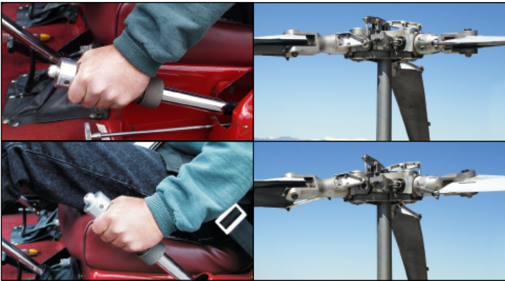
Figure 4-1. Raising the collective pitch control increases the pitch angle the same amount on all blades.
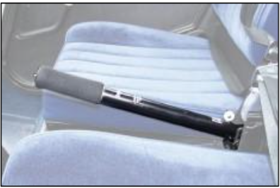
Figure 4-2. A twist grip throttle is usually mounted on the end of the collective lever. Some turbine helicopters have the throttles mounted on the overhead panel or on the floor in the cockpit.
has to be moved manually with the twist grip in order to maintain r.p.m. Twisting the throttle outboard increases r.p.m.; twisting it inboard decreases r.p.m. [Figure 4-2]
Collective pitch / throttle coordination
When the collective pitch is raised, the load on the engine is increased in order to maintain desired r.p.m. The load is measured by a manifold pressure gauge in piston helicopters or by a torque gauge in turbine helicopters.
In piston helicopters, the collective pitch is the primary control for manifold pressure, and the throttle is the primary control for r.p.m. However, the collective pitch control also influences r.p.m., and the throttle also influences manifold pressure; therefore, each is considered to be a secondary control of the other’s function. Both the tachometer (r.p.m. indicator) and the manifold pressure gauge must be analyzed to determine which control to use. Figure 4-3 illustrates this relationship.
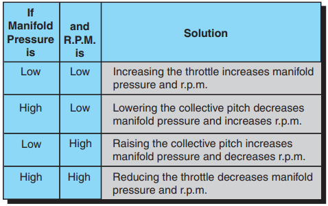
Figure 4-3. Relationship between manifold pressure, r.p.m., collective, and throttle.
Correlator / governor
A correlator is a mechanical connection between the collective lever and the engine throttle. When the col- lective lever is raised, power is automatically increased and when lowered, power is decreased. This system maintains r.p.m. close to the desired value, but still requires adjustment of the throttle for fine tuning.
A governor is a sensing device that senses rotor and engine r.p.m. and makes the necessary adjustments in order to keep rotor r.p.m. constant. In normal operations, once the rotor r.p.m. is set, the governor keeps the r.p.m. constant, and there is no need to make any throttle adjust- ments. Governors are common on all turbine helicopters and used on some piston powered helicopters.
Some helicopters do not have correlators or governors and require coordination of all collective and throttle movements. When the collective is raised, the throttle must be increased; when the collective is lowered, the throttle must be decreased. As with any aircraft control, large adjustments of either collective pitch or throttle should be avoided. All corrections should be made through the use of smooth pressure.
Cyclic pitch control
The cyclic pitch control tilts the main rotor disc by changing the pitch angle of the rotor blades in their cycle of rotation. When the main rotor disc is tilted, the horizontal component of lift moves the helicopter in the direction of tilt. [Figure 4-4]
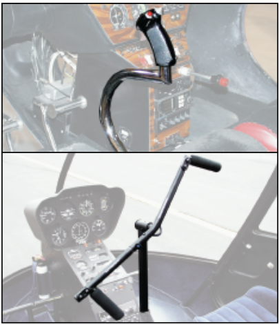
Figure 4-4. The cyclic pitch control may be mounted verti- cally between the pilot’s knees or on a teetering bar from a single cyclic located in the center of the helicopter. The cyclic can pivot in all directions.
The rotor disc tilts in the direction that pressure is applied to the cyclic pitch control. If the cyclic is moved forward, the rotor disc tilts forward; if the cyclic is moved aft, the disc tilts aft, and so on. Because the rotor disc acts like a gyro, the mechanical linkages for the cyclic control rods are rigged in such a way that they decrease the pitch angle of the rotor blade approximately 90° before it reaches the direction of cyclic displacement, and increase the pitch angle of the rotor blade approximately 90° after it passes the direction of displacement. An increase in pitch angle increases angle of attack; a decrease in pitch angle decreases angle of attack. For example, if the cyclic is moved forward, the angle of attack decreases as the rotor blade passes the right side of the helicopter and increases on the left side. This results in maximum downward deflection of the rotor blade in front of the helicopter and maximum upward deflection behind it, causing the rotor disc to tilt forward.
Antitorque pedals
The antitorque pedals, located on the cabin floor by the pilot’s feet, control the pitch, and therefore the thrust, of the tail rotor blades. [Figure 4-5] . The main purpose of the tail rotor is to counteract the torque effect of the main rotor. Since torque varies with changes in power, the tail rotor thrust must also be varied. The pedals are connected to the pitch change mechanism on the tail rotor gearbox and allow the pitch angle on the tail rotor blades to be increased or decreased.
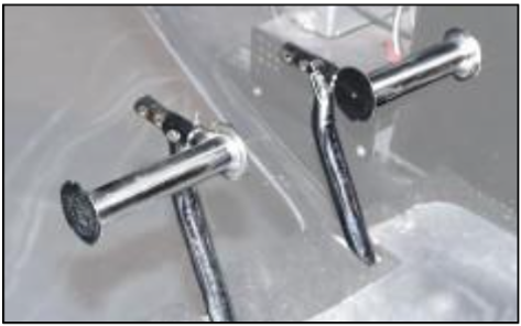
Figure 4-5. Antitorque pedals compensate for changes in torque and control heading in a hover.
HEADING CONTROL
Besides counteracting torque of the main rotor, the tail rotor is also used to control the heading of the helicopter while hovering or when making hovering turns. Hovering turns are commonly referred to as “pedal turns.”
In forward flight, the antitorque pedals are not used to control the heading of the helicopter, except during por- tions of crosswind takeoffs and approaches. Instead they are used to compensate for torque to put the helicopter in longitudinal trim so that coordinated flight can be main- tained. The cyclic control is used to change heading by making a turn to the desired direction.
The thrust of the tail rotor depends on the pitch angle of the tail rotor blades. This pitch angle can be positive, neg- ative, or zero. A positive pitch angle tends to move the tail to the right. A negative pitch angle moves the tail to the left, while no thrust is produced with a zero pitch angle.
With the right pedal moved forward of the neutral posi- tion, the tail rotor either has a negative pitch angle or a small positive pitch angle. The farther it is forward, the larger the negative pitch angle. The nearer it is to neu- tral, the more positive the pitch angle, and somewhere in between, it has a zero pitch angle. As the left pedal is moved forward of the neutral position, the positive pitch angle of the tail rotor increases until it becomes maxi- mum with full forward displacement of the left pedal.
If the tail rotor has a negative pitch angle, tail rotor thrust is working in the same direction as the torque of the main rotor. With a small positive pitch angle, the tail rotor does not produce sufficient thrust to overcome the torque effect of the main rotor during cruise flight. Therefore, if the right pedal is displaced forward of neutral during cruising flight, the tail rotor thrust does not overcome the torque effect, and the nose yaws to the right. [Figure 4-6]
With the antitorque pedals in the neutral position, the tail rotor has a medium positive pitch angle. In medium positive pitch, the tail rotor thrust approximately equals the torque of the main rotor during cruise flight, so the helicopter maintains a constant heading in level flight.
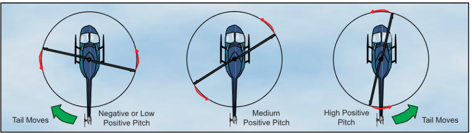
Figure 4-6. Tail rotor pitch angle and thrust in relation to pedal positions during cruising flight.
If the left pedal is in a forward position, the tail rotor has a high positive pitch position. In this position, tail rotor thrust exceeds the thrust needed to overcome torque effect during cruising flight so the helicopter yaws to the left.
The above explanation is based on cruise power and air- speed. Since the amount of torque is dependent on the amount of engine power being supplied to the main rotor, the relative positions of the pedals required to counteract torque depend upon the amount of power being used at any time. In general, the less power being used, the greater the requirement for forward displacement of the right pedal; the greater the power, the greater the forward displacement of the left pedal.
The maximum positive pitch angle of the tail rotor is generally somewhat greater than the maximum negative pitch angle available. This is because the primary purpose of the tail rotor is to counteract the torque of the main rotor. The capability for tail rotors to produce thrust to the left (negative pitch angle) is necessary, because during autorotation the drag of the transmission tends to yaw the nose to the left, or in the same direction the main rotor is turning.


