January 9th, 1923, marked the first officially observed flight of an autogyro. The aircraft, designed by Juan de la Cierva, introduced rotor technology that made for- ward flight in a rotorcraft possible. Until that time, rotary-wing aircraft designers were stymied by the problem of a rolling moment that was encountered when the aircraft began to move forward. This rolling moment was the product of airflow over the rotor disc, causing an increase in lift of the advancing blade and decrease in lift of the retreating blade. Cierva’s successful design, the C.4, introduced the articulated rotor, on which the blades were hinged and allowed to flap. This solution allowed the advancing blade to move upward, decreasing angle of attack and lift, while the retreating blade would swing downward, increasing angle of attack and lift. The result was balanced lift across the rotor disc regardless of airflow. This breakthrough was instrumental in the success of the modern helicopter, which was developed over 15 years later. (For more information on dissymmetry of lift, refer to Chapter 3— Aerodynamics of Flight.) On April 2, 1931, the Pitcairn PCA-2 autogyro was granted Type Certificate No. 410 and became the first rotary wing aircraft to be certified in the United States. The term “autogyro” was used to describe this type of aircraft until the FAA later designated them “gyroplanes.”
By definition, the gyroplane is an aircraft that achieves lift by a free spinning rotor. Several aircraft have used the free spinning rotor to attain performance not avail- able in the pure helicopter. The “gyrodyne” is a hybrid rotorcraft that is capable of hovering and yet cruises in autorotation. The first successful example of this type of aircraft was the British Fairy Rotodyne, certificated to the Transport Category in 1958. During the 1960s and 1970s, the popularity of gyroplanes increased with the certification of the McCulloch J-2 and Umbaugh. The latter becoming the Air & Space 18A.
There are several aircraft under development using the free spinning rotor to achieve rotary wing takeoff performance and fixed wing cruise speeds. The gyroplane offers inherent safety, simplicity of operation, and out- standing short field point-to-point capability.
Types of gyroplanes
Because the free spinning rotor does not require an antitorque device, a single rotor is the predominate configuration. Counter-rotating blades do not offer any particular advantage. The rotor system used in a gyroplane may have any number of blades, but the most popular are the two and three blade systems. Propulsion for gyroplanes may be either tractor or pusher, meaning the engine may be mounted on the front and pull the aircraft, or in the rear, pushing it through the air. The powerplant itself may be either reciprocating or turbine. Early gyroplanes were often a derivative of tractor configured airplanes with the rotor either replacing the wing or acting in conjunction with it. However, the pusher configuration is generally more maneuverable due to the placement of the rudder in the propeller slipstream, and also has the advantage of better visibility for the pilot. [Figure 15-1]
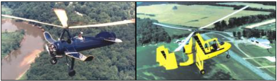
Figure 15-1. The gyroplane may have wings, be either tractor or pusher configured, and could be turbine or propeller powered. Pictured are the Pitcairn PCA-2 Autogyro (left) and the Air & Space 18A gyroplane.
When direct control of the rotor head was perfected, the jump takeoff gyroplane was developed. Under the proper conditions, these gyroplanes have the ability to lift off vertically and transition to forward flight. Later developments have included retaining the direct control rotor head and utilizing a wing to unload the rotor, which results in increased forward speed.
Components
Although gyroplanes are designed in a variety of configurations, for the most part the basic components are the same. The minimum components required for a functional gyroplane are an airframe, a powerplant, a rotor system, tail surfaces, and landing gear. [Figure 15-2] An optional component is the wing, which is incorporated into some designs for specific performance objectives.
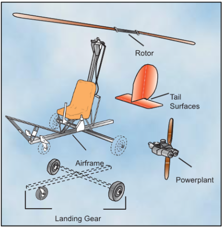
Figure 15-2. Gyroplanes typically consist of five major com- ponents. A sixth, the wing, is utilized on some designs.
AIRFRAME
The airframe provides the structure to which all other components are attached. Airframes may be welded tube, sheet metal, composite, or simply tubes bolted together. A combination of construction methods may also be employed. The airframes with the greatest strength-to-weight ratios are a carbon fiber material or the welded tube structure, which has been in use for a number of years.
POWERPLANT
The powerplant provides the thrust necessary for forward flight, and is independent of the rotor system while in flight. While on the ground, the engine may be used as a source of power to prerotate the rotor system. Over the many years of gyroplane development, a wide variety of engine types have been adapted to the gyro- plane. Automotive, marine, ATV, and certificated aircraft engines have all been used in various gyroplane designs. Certificated gyroplanes are required to use FAA certificated engines. The cost of a new certificated aircraft engine is greater than the cost of nearly any other new engine. This added cost is the primary reason other types of engines are selected for use in amateur built gyroplanes.
ROTOR SYSTEM
The rotor system provides lift and control for the gyro- plane. The fully articulated and semi-rigid teetering rotor systems are the most common. These are explained in-depth in Chapter 5—Main Rotor System. The teeter blade with hub tilt control is most common in homebuilt gyroplanes. This system may also employ a collective control to change the pitch of the rotor blades. With sufficient blade inertia and collective pitch change, jump takeoffs can be accomplished.
TAIL SURFACES
The tail surfaces provide stability and control in the pitch and yaw axes. These tail surfaces are similar to an air- plane empennage and may be comprised of a fin and rudder, stabilizer and elevator. An aft mounted duct enclosing the propeller and rudder has also been used. Many gyroplanes do not incorporate a horizontal tail surface.
On some gyroplanes, especially those with an enclosed cockpit, the yaw stability is marginal due to the large fuselage side area located ahead of the center of gravity. The additional vertical tail surface necessary to compensate for this instability is difficult to achieve as the confines of the rotor tilt and high landing pitch attitude limits the available area. Some gyroplane designs incorporate multiple vertical stabilizers and rudders to add additional yaw stability.
Direct Control—The capacity for the pilot to maneuver the aircraft by tilting the rotor disc and, on some gyroplanes, affect changes in pitch to the rotor blades. These equate to cyclic and collective control, which were not available in earlier autogyros.
Unload—To reduce the component of weight supported by the rotor system.
Prerotate—Spinning a gyroplane rotor to sufficient r.p.m. prior to flight.
LANDING GEAR
The landing gear provides the mobility while on the ground and may be either conventional or tricycle. Conventional gear consists of two main wheels, and one under the tail. The tricycle configuration also uses two mains, with the third wheel under the nose. Early auto- gyros, and several models of gyroplanes, use conven- tional gear, while most of the later gyroplanes incorporate tricycle landing gear. As with fixed wing aircraft, the gyroplane landing gear provides the ground mobility not found in most helicopters.
WINGS
Wings may or may not comprise a component of the gyroplane. When used, they provide increased performance, increased storage capacity, and increased stability. Gyroplanes are under development with wings that are capable of almost completely unloading the rotor system and carrying the entire weight of the aircraft. This will allow rotary wing takeoff performance with fixed wing cruise speeds. [Figure 15-3]
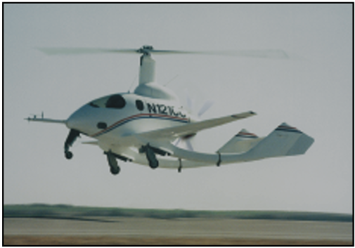
Figure 15-3. The CarterCopter uses wings to enhance performance.


