Your ability to predict the performance of a helicopter is extremely important. It allows you to determine how much weight the helicopter can carry before takeoff, if your helicopter can safely hover at a specific altitude and temperature, how far it will take to climb above obstacles, and what your maximum climb rate will be.
Factors affecting performance
A helicopter’s performance is dependent on the power output of the engine and the lift production of the rotors, whether it is the main rotor(s) or tail rotor. Any factor that affects engine and rotor efficiency affects performance. The three major factors that affect performance are density altitude, weight, and wind.
DENSITY ALTITUDE
The density of the air directly affects the performance of the helicopter. As the density of the air increases, engine power output, rotor efficiency, and aerodynamic lift all increase. Density altitude is the altitude above mean sea level at which a given atmospheric density occurs in the standard atmosphere. It can also be interpreted as pressure altitude corrected for nonstandard temperature differences.
Pressure altitude is displayed as the height above a standard datum plane, which, in this case, is a theoretical plane where air pressure is equal to 29.92 in. Hg. Pressure altitude is the indicated height value on the altimeter when the altimeter setting is adjusted to29.92 in. Hg. Pressure altitude, as opposed to true altitude, is an important value for calculating performance as it more accurately represents the air content at a particular level. The difference between true altitude
Density Altitude—Pressure altitude corrected for nonstandard temperature variations. Performance charts for many older aircraft are based on this value.
Standard Atmosphere—At sea level, the standard atmosphere consists of a barometric pressure of 29.92 inches of mercury (in. Hg.) or 1013.2 millibars, and a temperature of 15°C (59°F). Pressure and temperature normally decrease as altitude increases. The standard lapse rate in the lower atmosphere for each 1,000 feet of altitude is approximately 1 in. Hg. and 2°C (3.5°F). For example, the standard pressure and temperature at 3,000 feet mean sea level (MSL) is 26.92 in. Hg. (29.92 – 3) and 9°C (15°C – 6°C).
and pressure altitude must be clearly understood. True altitude means the vertical height above mean sea level and is displayed on the altimeter when the altimeter is correctly adjusted to the local setting.
For example, if the local altimeter setting is 30.12 in. Hg., and the altimeter is adjusted to this value, the altimeter indicates exact height above sea level. However, this does not reflect conditions found at this height under standard conditions. Since the altimeter setting is more than 29.92 in. Hg., the air in this example has a higher pressure, and is more compressed, indicative of the air found at a lower altitude. Therefore, the pressure altitude is lower than the actual height above mean sea level.
To calculate pressure altitude without the use of an altimeter, remember that the pressure decreases approximately 1 inch of mercury for every 1,000-foot increase in altitude. For example, if the current local altimeter setting at a 4,000-foot elevation is 30.42, the pressure altitude would be 3,500 feet. (30.42 – 29.92 =
.50 in. Hg. 3 1,000 feet = 500 feet. Subtracting 500 feet
from 4,000 equals 3,500 feet).
The four factors that most affect density altitude are: atmospheric pressure, altitude, temperature, and the moisture content of the air.
ATMOSPHERIC PRESSURE
Due to changing weather conditions, atmospheric pressure at a given location changes from day to day. If the pressure is lower, the air is less dense. This means a higher density altitude and less helicopter performance.
Pressure Altitude—The height above the standard pressure level of
29.92 in. Hg. It is obtained by setting 29.92 in the barometric pressure window and reading the altimeter.
True Altitude—The actual height of an object above mean sea level.
ALTITUDE
As altitude increases, the air becomes thinner or less dense. This is because the atmospheric pressure acting on a given volume of air is less, allowing the air molecules to move further apart. Dense air contains more air molecules spaced closely together, while thin air contains less air molecules because they are spaced further apart. As altitude increases, density altitude increases.
TEMPERATURE
Temperature changes have a large affect on density altitude. As warm air expands, the air molecules move further apart, creating less dense air. Since cool air contracts, the air molecules move closer together, creating denser air. High temperatures cause even low elevations to have high density altitudes.
MOISTURE (HUMIDITY)
The water content of the air also changes air density because water vapor weighs less than dry air. Therefore, as the water content of the air increases, the air becomes less dense, increasing density altitude and decreasing performance.
Humidity, also called “relative humidity,” refers to the amount of water vapor contained in the atmosphere, and is expressed as a percentage of the maximum amount of water vapor the air can hold. This amount varies with temperature; warm air can hold more water vapor, while colder air can hold less. Perfectly dry air that contains no water vapor has a relative humidity of 0 percent, while saturated air that cannot hold any more water vapor, has a relative humidity of 100 percent.
Humidity alone is usually not considered an important factor in calculating density altitude and helicopter performance; however, it does contribute. There are no rules-of-thumb or charts used to compute the effects of humidity on density altitude, so you need to take this into consideration by expecting a decrease in hovering and takeoff performance in high humidity conditions.
HIGH AND LOW
DENSITY ALTITUDE CONDITIONS
You need to thoroughly understand the terms “high density altitude” and “low density altitude.” In general, high density altitude refers to thin air, while low density altitude refers to dense air. Those conditions that result in a high density altitude (thin air) are high elevations, low atmospheric pressure, high temperatures, high humidity, or some combination thereof. Lower elevations, high atmospheric pressure, low temperatures, and low humidity are more indicative of low density altitude (dense air). However, high density altitudes may be present at lower elevations on hot days, so it is important to calculate the density altitude and determine performance before a flight.
One of the ways you can determine density altitude is through the use of charts designed for that purpose. [Figure 8-1]. For example, assume you are planning to depart an airport where the field elevation is 1,165 feet MSL, the altimeter setting is 30.10, and the temperature is 70°F. What is the density altitude? First, correct for nonstandard pressure (30.10) by referring to the right side of the chart, and subtracting 165 feet from the field elevation. The result is a pressure altitude of 1,000 feet. Then, enter the chart at the bottom, just above the temperature of 70°F (21°C). Proceed up the chart vertically until you intercept the diagonal 1,000- foot pressure altitude line, then move horizontally to the left and read the density altitude of approximately 2,000 feet. This means your helicopter will perform as if it were at 2,000 feet MSL on a standard day.
Most performance charts do not require you to compute density altitude. Instead, the computation is built into the performance chart itself. All you have to do is enter the chart with the correct pressure altitude and the temperature.
WEIGHT
Lift is the force that opposes weight. As weight increases, the power required to produce the lift needed to compensate for the added weight must also increase. Most performance charts include weight as one of the variables. By reducing the weight of the helicopter, you may find that you are able to safely take off or land at a location that otherwise would be impossible. However, if you are ever in doubt about whether you can safely perform a takeoff or landing, you should delay your takeoff until more favorable density altitude conditions exist. If airborne, try to land at a location that has more favorable conditions, or one where you can make a landing that does not require a hover.
In addition, at higher gross weights, the increased power required to hover produces more torque, which means more antitorque thrust is required. In some helicopters, during high altitude operations, the maximum antitorque produced by the tail rotor during a hover may not be sufficient to overcome torque even if the gross weight is within limits.
WINDS
Wind direction and velocity also affect hovering, take- off, and climb performance. Translational lift occurs anytime there is relative airflow over the rotor disc. This occurs whether the relative airflow is caused by helicopter movement or by the wind. As wind speed increases, translational lift increases, resulting in less power required to hover.
The wind direction is also an important consideration. Headwinds are the most desirable as they contribute to the most increase in performance. Strong crosswinds
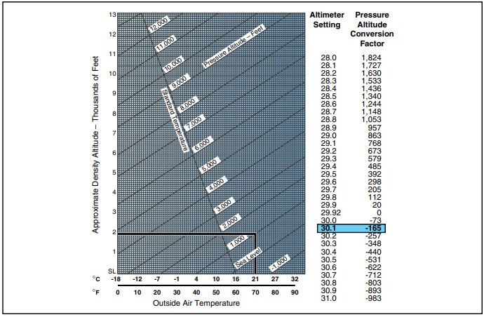
Figure 8-1. Density Altitude Chart.
and tailwinds may require the use of more tail rotor thrust to maintain directional control. This increased tail rotor thrust absorbs power from the engine, which means there is less power available to the main rotor for the production of lift. Some helicopters even have a critical wind azimuth or maximum safe relative wind chart. Operating the helicopter beyond these limits could cause loss of tail rotor effectiveness.
Takeoff and climb performance is greatly affected by wind. When taking off into a headwind, effective translational lift is achieved earlier, resulting in more lift and a steeper climb angle. When taking off with a tailwind, more distance is required to accelerate through translation lift.
Performance charts
In developing performance charts, aircraft manufacturers make certain assumptions about the condition of the helicopter and the ability of the pilot. It is assumed that the helicopter is in good operating condition and the engine is developing its rated power. The pilot is assumed to be following normal operating procedures and to have average flying abilities. Average means a pilot capable of doing each of the required tasks correctly and at the appropriate times.
Using these assumptions, the manufacturer develops performance data for the helicopter based on actual flight tests. However, they do not test the helicopter under each and every condition shown on a performance chart. Instead, they evaluate specific data and mathematically derive the remaining data.
HOVERING PERFORMANCE
Helicopter performance revolves around whether or not the helicopter can be hovered. More power is required during the hover than in any other flight regime. Obstructions aside, if a hover can be maintained, a takeoff can be made, especially with the additional benefit of translational lift. Hover charts are provided for in ground effect (IGE) hover and out of ground effect (OGE) hover under various conditions of gross weight, altitude, temperature, and power. The “in ground effect” hover ceiling is usually higher than the “out of ground effect” hover ceiling because of the added lift benefit produced by ground effect.
In Ground Effect (IGE) Hover—Hovering close to the surface (usually less than one rotor diameter above the surface) under the influence of ground effect.
Out of Ground Effect (OGE) Hover—Hovering greater than one rotor diameter distance above the surface. Because induced drag is greater while hovering out of ground effect, it takes more power to achieve a hover. See Chapter 3—Aerodynamics of Flight for more details on IGE and OGE hover.
As density altitude increases, more power is required to hover. At some point, the power required is equal to the power available. This establishes the hovering ceiling under the existing conditions. Any adjustment to the gross weight by varying fuel, payload, or both, affects the hovering ceiling. The heavier the gross weight, the lower the hovering ceiling. As gross weight is decreased, the hover ceiling increases.
SAMPLE PROBLEM 1
You are to fly a photographer to a remote location to
take pictures of the local wildlife. Using figure 8-2, can
you safely hover in ground effect at your departure
point with the following conditions?
Pressure Altitude…………………………….8,000 feet
Temperature………………………………………..+15°C
Takeoff Gross Weight…………………1,250 pounds
R.P.M………………………………………………….104%
First enter the chart at 8,000 feet pressure altitude (point A), then move right until reaching a point mid- way between the +10°C and +20°C lines (point B). From that point, proceed down to find the maximum gross weight where a 2 foot hover can be achieved. In this case, it is approximately 1,280 pounds (point C).
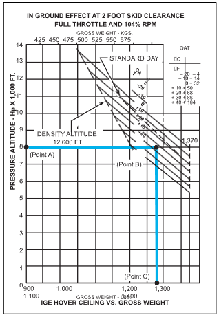
Figure 8-2. In Ground Effect Hover Ceiling versus Gross Weight Chart.
Since the gross weight of your helicopter is less than this, you can safely hover with these conditions.
SAMPLE PROBLEM 2
Once you reach the remote location in the previous problem, you will need to hover out of ground effect for some of the pictures. The pressure altitude at the remote site is 9,000 feet, and you will use 50 pounds of fuel getting there. (The new gross weight is now 1,200 pounds.) The temperature will remain at +15°C. Using figure 8-3, can you accomplish the mission?
Enter the chart at 9,000 feet (point A) and proceed to point B (+15°C). From there determine that the maxi- mum gross weight to hover out of ground effect is approximately 1,130 pounds (point C). Since your gross weight is higher than this value, you will not be able to hover with these conditions. To accomplish the mission, you will have to remove approximately 70 pounds before you begin the flight.
These two sample problems emphasize the importance of determining the gross weight and hover ceiling throughout
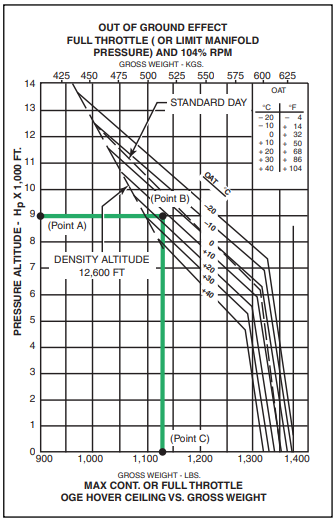
Figure 8-3. Out of Ground Effect Hover Ceiling versus Gross Weight Chart.
the entire flight operation. Being able to hover at the take- off location with a certain gross weight does not ensure the same performance at the landing point. If the destination point is at a higher density altitude because of higher ele- vation, temperature, and/or relative humidity, more power is required to hover. You should be able to predict whether hovering power will be available at the destination by knowing the temperature and wind conditions, using the performance charts in the helicopter flight manual, and making certain power checks during hover and in flight prior to commencing the approach and landing.
TAKEOFF PERFORMANCE
If takeoff charts are included in the rotorcraft flight man- ual, they usually indicate the distance it takes to clear a 50- foot obstacle based on various conditions of weight, pressure altitude, and temperature. In addition, the values computed in the takeoff charts usually assume that the flight profile is per the applicable height-velocity diagram.
SAMPLE PROBLEM 3
In this example, determine the distance to clear a 50-
foot obstacle with the following conditions:
Pressure Altitude…………………………….5,000 feet
Takeoff Gross Weight…………………2,850 pounds
Temperature ………………………………………….95°F
Using figure 8-4, locate 2,850 pounds in the first column. Since the pressure altitude of 5,000 feet is not one of the choices in column two, you have to interpolate between the values from the 4,000- and 6,000-foot lines. Follow each of these rows out to the column headed by 95°F. The values are 1,102 feet and 1,538 feet. Since 5,000 is halfway between 4,000 and 6,000, the interpolated value should be halfway between these two values or 1,320 feet ([1,102 + 1,538] 4 2 = 1,320).
CLIMB PERFORMANCE
Most of the factors affecting hover and takeoff per- formance also affect climb performance. In addition, turbulent air, pilot techniques, and overall condition of the helicopter can cause climb performance to vary.
A helicopter flown at the “best rate-of-climb” speed will obtain the greatest gain in altitude over a given period of time. This speed is normally used during the climb after all obstacles have been cleared and is usu- ally maintained until reaching cruise altitude. Rate of climb must not be confused with angle of climb. Angle of climb is a function of altitude gained over a given distance. The best rate-of-climb speed results in the highest climb rate, but not the steepest climb angle and may not be sufficient to clear obstructions. The “best angle-of-climb” speed depends upon the power available. If there is a surplus of power available, the helicopter can climb vertically, so the best angle-of- climb speed is zero.
Wind direction and speed have an effect on climb performance, but it is often misunderstood. Airspeed is the speed at which the helicopter is moving through the atmosphere and is unaffected by wind. Atmospheric wind affects only the groundspeed, or speed at which the helicopter is moving over the earth’s surface. Thus, the only climb performance
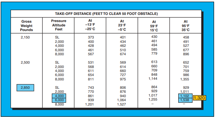
Figure 8-4. Takeoff Distance Chart.
affected by atmospheric wind is the angle of climb and not the rate of climb.
SAMPLE PROBLEM 4
Determine the best rate of climb using figure 8-5. Use
the following conditions:
Pressure Altitude…………………………..12,000 feet
Outside Air Temperature ………………………+10°C
Gross Weight…………………………….3,000 pounds
Power …………………………………….Takeoff Power
Anti-ice ………………………………………………….ON
Indicated Airspeed ……………………………52 knots
With this chart, first locate the temperature of +10°C (point A). Then proceed up the chart to the 12,000-foot pressure altitude line (point B). From there, move hori- zontally to the right until you intersect the 3,000-foot line (point C). With this performance chart, you must now determine the rate of climb with anti-ice off and then subtract the rate of climb change with it on. From point C, go to the bottom of the chart and find that the maximum rate of climb with anti-ice off is approxi- mately 890 feet per minute. Then, go back to point C and up to the anti-ice-on line (point D). Proceed hori- zontally to the right and read approximately 240 feet per minute change (point E). Now subtract 240 from 890 to get a maximum rate of climb, with anti-ice on, of 650 feet per minute.
Other rate-of-climb charts use density altitude as a starting point. [Figure 8-6] While it cleans up the chart somewhat, you must first determine density altitude. Notice also that this chart requires a change in the indicated airspeed with a change in altitude.
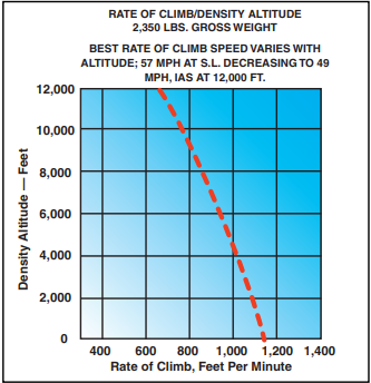
Figure 8-6. This chart uses density altitude in determining maximum rate of climb.
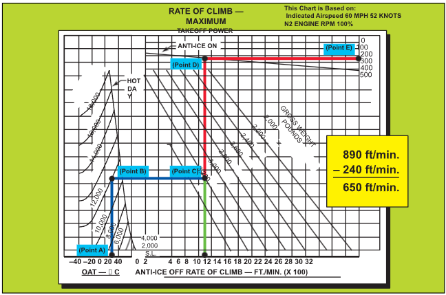
Figure 8-5. Maximum Rate-of-Climb Chart.


