As with most certificated aircraft manufactured after March 1979, FAA-certificated gyroplanes are required to have an approved flight manual. The flight manual describes procedures and limitations that must be adhered to when operating the aircraft. Specification for Pilot’s Operating Handbook, published by the General Aviation Manufacturers Association (GAMA), provides a recommended format that more recent gyro- plane flight manuals follow. [Figure 19-1]
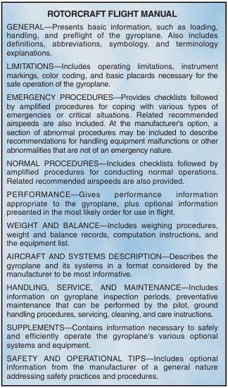
Figure 19-1. The FAA-approved flight manual may contain as many as ten sections, as well as an optional alphabetical index.
This format is the same as that used by helicopters, which is explained in depth in Chapter 6—Rotorcraft Flight Manual (Helicopter).
Amateur-built gyroplanes may have operating limitations but are not normally required to have an approved flight manual. One exception is an exemption granted by the FAA that allows the commercial use of two-place, amateur-built gyroplanes for instructional purposes. One of the conditions of this exemption is to have an approved flight manual for the aircraft. This manual is to be used for training purposes, and must be carried in the gyroplane at all times.
Using the flight manual
The flight manual is required to be on board the aircraft to guarantee that the information contained therein is readily available. For the information to be of value, you must be thoroughly familiar with the manual and be able to read and properly interpret the various charts and tables.
WEIGHT AND BALANCE SECTION
The weight and balance section of the flight manual contains information essential to the safe operation of the gyroplane. Careful consideration must be given to the weight of the passengers, baggage, and fuel prior to each flight. In conducting weight and balance computations, many of the terms and procedures are similar to those used in helicopters. These are further explained in Chapter 7—Weight and Balance. In any aircraft, failure to adhere to the weight and balance limitations prescribed by the manufacturer can be extremely hazardous.
SAMPLE PROBLEM
As an example of a weight and balance computation, assume a sightseeing flight in a two-seat, tandem-con- figured gyroplane with two people aboard. The pilot, seated in the front, weighs 175 pounds while the rear seat passenger weighs 160 pounds. For the purposes of this example, there will be no baggage carried. The basic empty weight of the aircraft is 1,315 pounds with a moment, divided by 1,000, of 153.9 pound-inches.
Using the loading graph [Figure 19-2], the moment/1000 of the pilot is found to be 9.1 pound- inches, and the passenger has a moment/1000 of 13.4 pound-inches.
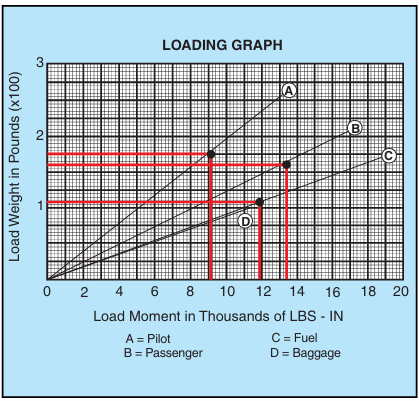
Figure 19-2. A loading graph is used to determine the load moment for weights at various stations.
Adding these figures, the total weight of the aircraft for this flight (without fuel) is determined to be 1,650 pounds with a moment/1000 of 176.4 pound-inches. [Figure 19-3]
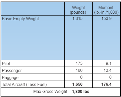
Figure 19-3. Loading of the sample aircraft, less fuel.
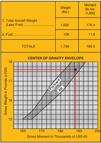
The maximum gross weight for the sample aircraft is 1,800 pounds, which allows up to 150 pounds to be car- ried in fuel. For this flight, 18 gallons of fuel is deemed sufficient. Allowing six pounds per gallon of fuel, the fuel weight on the aircraft totals 108 pounds. Referring again to the loading graph [Figure 19-2], 108 pounds of fuel would have a moment/1000 of 11.9 pound-inches. This is added to the previous totals to obtain the total aircraft weight of 1,758 pounds and a moment/1000 of 88.3. Locating this point on the center of gravity envelope chart [Figure 19-4], shows that the loading is within the prescribed weight and balance limits.
PERFORMANCE SECTION
The performance section of the flight manual contains data derived from actual flight testing of the aircraft. Because the actual performance may differ, it is pru- dent to maintain a margin of safety when planning operations using this data.
SAMPLE PROBLEM
For this example, a gyroplane at its maximum gross weight (1,800 lbs.) needs to perform a short field take- off due to obstructions in the takeoff path. Present weather conditions are standard temperature at a pressure altitude of 2,000 feet, and the wind is calm. Referring to the appropriate performance chart [Figure 19-5], the takeoff distance to clear a 50-foot obstacle is determined by entering the chart from the left at the pressure altitude of 2,000 feet. You then proceed horizontally to the right until intersecting the appropriate temperature reference line, which in this case is the dashed standard temperature line. From this point, descend vertically to find the total takeoff distance to clear a 50-foot obstacle. For the conditions given, this particular gyroplane would require a distance of 940 feet for ground roll and the distance needed to climb 50 feet above the surface. Notice that the data presented in this chart is predicated on certain conditions, such as a running takeoff to 30 m.p.h., a 50 m.p.h. climb speed, a
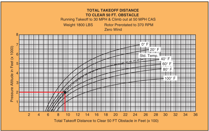
Figure 19-5. Takeoff performance chart.
rotor prerotation speed of 370 r.p.m., and no wind. Variations from these conditions alter performance, possibly to the point of jeopardizing the successful out- come of the maneuver.
HEIGHT/VELOCITY DIAGRAM
Like helicopters, gyroplanes have a height/velocity diagram that defines what speed and altitude combina- tions allow for a safe landing in the event of an engine failure. [Figure 19-6]
During an engine-out landing, the cyclic flare is used to arrest the vertical velocity of the aircraft and most of the forward velocity. On gyroplanes with a manual collec- tive control, increasing blade pitch just prior to touch- down can further reduce ground roll. Typically, a gyroplane has a lower rotor disc loading than a helicop- ter, which provides a slower rate of descent in autorota- tion. The power required to turn the main transmission, tail rotor transmission, and tail rotor also add to the higher descent rate of a helicopter in autorotation as compared with that of a gyroplane.
EMERGENCY SECTION
Because in-flight emergencies may not allow enough time to reference the flight manual, the emergency sec- tion should be reviewed periodically to maintain familiarity with these procedures. Many aircraft also use placards and instrument markings in the cockpit, which provide important information that may not be committed to memory.
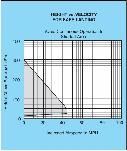
Figure 19-6. Operations within the shaded area of a height/velocity diagram may not allow for a safe landing and are to be avoided.
Hang test
The proper weight and balance of a gyroplane without a flight manual is normally determined by conducting a hang test of the aircraft. This is achieved by removing the rotor blades and suspending the aircraft by its teeter bolt, free from contact with the ground. A measurement is then taken, either at the keel or the rotor mast, to determine how many degrees from level the gyroplane hangs. This number must be within the range specified by the manufacturer. For the test to reflect the true balance of the aircraft, it is important that it be conducted using the actual weight of the pilot and all gear normally carried in flight. Additionally, the measurement should be taken both with the fuel tank full and with it empty to ensure that fuel burn does not affect the loading.


