Title 14 of the Code of Federal Regulations (14 CFR) part 91 requires that pilots comply with the operating limitations specified in approved rotorcraft flight manuals, markings, and placards. Originally, flight manuals were often characterized by a lack of essential information and followed whatever format and content the manufacturer felt was appropriate. This changed with the acceptance of the General Aviation Manufacturers Association’s (GAMA) Specification for Pilot’s Operating Handbook, which established a standardized format for all general aviation airplane and rotorcraft flight manuals. The term “Pilot’s Operating Handbook (POH)” is often used in place of “Rotorcraft Flight Manual (RFM).” However, if “Pilot’s Operating Handbook” is used as the main title instead of “Rotorcraft Flight Manual,” a statement must be included on the title page indicating that the document is the FAA-Approved Rotorcraft Flight Manual. [Figure 6-1]
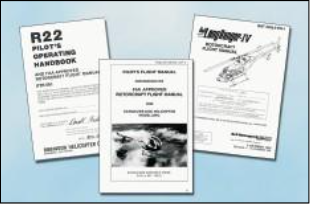
Figure 6-1. The Rotorcraft Flight Manual is a regulatory docu- ment in terms of the maneuvers, procedures, and operating limitations described therein.
Besides the preliminary pages, an FAA-Approved Rotorcraft Flight Manual may contain as many as ten sec- tions. These sections are: General Information; Operating Limitations; Emergency Procedures; Normal Procedures; Performance; Weight and Balance; Aircraft and Systems Description; Handling, Servicing, and Maintenance; and Supplements. Manufacturers have the option of including a tenth section on Safety and Operational Tips and an alphabetical index at the end of the handbook.
Preliminary pages
While rotorcraft flight manuals may appear similar for the same make and model of aircraft, each flight manual is unique since it contains specific information about a particular aircraft, such as the equipment installed, and weight and balance information. Therefore, manufacturers are required to include the serial number and registration on the title page to iden- tify the aircraft to which the flight manual belongs. If a flight manual does not indicate a specific aircraft regis- tration and serial number, it is limited to general study purposes only.
Most manufacturers include a table of contents, which identifies the order of the entire manual by section number and title. Usually, each section also contains its own table of contents. Page numbers reflect the section you are reading, 1-1, 2-1, 3-1, and so on. If the flight manual is published in looseleaf form, each section is usually marked with a divider tab indicating the section number or title, or both. The Emergency Procedures section may have a red tab for quick identification and reference.
General information
The General Information section provides the basic descriptive information on the rotorcraft and the power- plant. In some manuals there is a three-view drawing of the rotorcraft that provides the dimensions of various components, including the overall length and width, and the diameter of the rotor systems. This is a good place to quickly familiarize yourself with the aircraft.
You can find definitions, abbreviations, explanations of symbology, and some of the terminology used in the manual at the end of this section. At the option of the manufacturer, metric and other conversion tables may also be included.
Operating limitations
The Operating Limitations section contains only those limitations required by regulation or that are necessary for the safe operation of the rotorcraft, powerplant, sys- tems, and equipment. It includes operating limitations, instrument markings, color coding, and basic placards. Some of the areas included are: airspeed, altitude, rotor, and powerplant limitations, including fuel and oil requirements; weight and loading distribution; and flight limitations.
AIRSPEED LIMITATIONS
Airspeed limitations are shown on the airspeed indica- tor by color coding and on placards or graphs in the aircraft. A red line on the airspeed indicator shows the airspeed limit beyond which structural damage could occur. This is called the never exceed speed, or VNE. The normal operating speed range is depicted by a green arc. A blue line is sometimes added to show the maximum safe autorotation speed. [Figure 6-2]
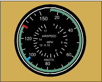
Figure 6-2. Typical airspeed indicator limitations and markings.
ALTITUDE LIMITATIONS
If the rotorcraft has a maximum operating density alti- tude, it is indicated in this section of the flight manual. Sometimes the maximum altitude varies based on differ- ent gross weights.
ROTOR LIMITATIONS
Low rotor r.p.m. does not produce sufficient lift, and high r.p.m. may cause structural damage, therefore rotor r.p.m. limitations have minimum and maximum values. A green arc depicts the normal operating range with red lines showing the minimum and maximum limits. [Figure 6-3]
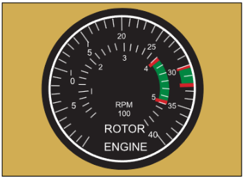
Figure 6-3. Markings on a typical dual-needle tachometer in a reciprocating-engine helicopter. The outer band shows the limits of the superimposed needles when the engine is turning the rotor. The inner band indicates the power-off limits
There are two different rotor r.p.m. limitations: power-on and power-off. Power-on limitations apply anytime the engine is turning the rotor and is depicted by a fairly nar- row green band. A yellow arc may be included to show a transition range, which means that operation within this range is limited. Power-off limitations apply anytime the engine is not turning the rotor, such as when in an autoro- tation. In this case, the green arc is wider than the power- on arc, indicating a larger operating range.
POWERPLANT LIMITATIONS
The Powerplant Limitations area describes operating limitations on the rotorcraft’s engine including such items as r.p.m. range, power limitations, operating temperatures, and fuel and oil requirements. Most turbine engines and some reciprocating engines have a maxi- mum power and a maximum continuous power rating. The “maximum power” rating is the maximum power the engine can generate and is usually limited by time. The maximum power range is depicted by a yellow arc on the engine power instruments, with a red line indicating the maximum power that must not be exceeded. “Maximum continuous power” is the maximum power the engine can generate continually, and is depicted by a green arc. [Figure 6-4]
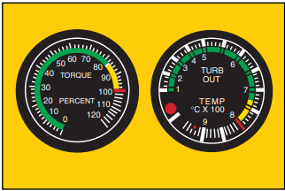
Figure 6-4. Torque and turbine outlet temperature (TOT) gauges are commonly used with turbine-powered aircraft.
Like on a torque and turbine outlet temperature gauge, the red line on a manifold pressure gauge indicates the maximum amount of power. A yellow arc on the gauge warns of pressures approaching the limit of rated power. A placard near the gauge lists the maximum readings for specific conditions. [Figure 6-5]
WEIGHT AND LOADING DISTRIBUTION
The Weight and Loading Distribution area contains the maximum certificated weights, as well as the center of gravity (CG) range. The location of the reference datum used in balance computations should also be included in this section. Weight and balance computations are not provided here, but rather in the Weight and Balance Section of the FAA-Approved Rotocraft Flight Manual.
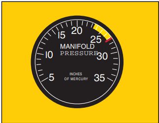
Figure 6-5. A manifold pressure gauge is commonly used with piston-powered aircraft.
FLIGHT LIMITATIONS
This area lists any maneuvers which are prohibited, such as acrobatic flight or flight into known icing con- ditions. If the rotorcraft can only be flown in VFR conditions, it will be noted in this area. Also included are the minimum crew requirements, and the pilot seat location, if applicable, where solo flights must be con- ducted.
PLACARDS
All rotorcraft generally have one or more placards dis- played that have a direct and important bearing on the safe operation of the rotorcraft. These placards are located in a conspicuous place within the cabin and normally appear in the Limitations Section. Since VNE changes with altitude, this placard can be found in all helicopters. [Figure 6-6]
Emergency procedures
Concise checklists describing the recommended procedures and airspeeds for coping with various types of emergencies or critical situations can be found in this section. Some of the emergencies covered include: engine failure in a hover and at altitude, tail rotor failures, fires, and systems failures. The procedures for restarting an engine and for ditching in the water might also be included.
Manufacturers may first show the emergencies check- lists in an abbreviated form with the order of items reflecting the sequence of action. This is followed by amplified checklists providing additional information to help you understand the procedure. To be prepared for an abnormal or emergency situation, memorize the first steps of each checklist, if not all the steps. If time permits, you can then refer to the checklist to make sure all items have been covered. (For more information on emergencies, refer to Chapter 11—Helicopter Emergencies and Chapter 21—Gyroplane Emergencies.)
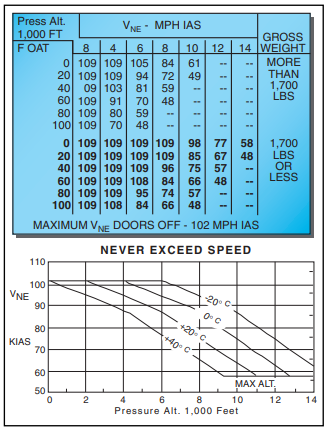
Figure 6-6. Various VNE placards.
Manufacturers also are encouraged to include an optional area titled “Abnormal Procedures,” which describes rec- ommended procedures for handling malfunctions that are not considered to be emergencies. This information would most likely be found in larger helicopters.
Normal procedures
The Normal Procedures is the section you will proba- bly use the most. It usually begins with a listing of the airspeeds, which may enhance the safety of normal operations. It is a good idea to memorize the airspeeds that are used for normal flight operations. The next part of the section includes several checklists, which take you through the preflight inspection, before starting procedure, how to start the engine, rotor engagement, ground checks, takeoff, approach, landing, and shut- down. Some manufacturers also include the procedures for practice autorotations. To avoid skipping an impor- tant step, you should always use a checklist when one is available. (More information on maneuvers can be found in Chapter 9—Basic Maneuvers, Chapter 10— Advanced Maneuvers, and Chapter 20—Gyroplane Flight Operations.)
Performance
The Performance Section contains all the information required by the regulations, and any additional performance information the manufacturer feels may enhance your ability to safely operate the rotorcraft.
These charts, graphs, and tables vary in style but all contain the same basic information. Some examples of the performance information that can be found in most flight manuals include a calibrated versus indicated airspeed conversion graph, hovering ceiling versus gross weight charts, and a height-velocity diagram. [Figure 6-7] For information on how to use the charts, graphs, and tables, refer to Chapter 8— Performance.
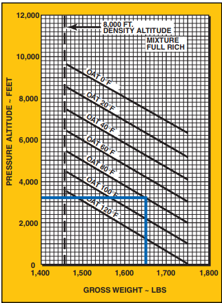
Figure 6-7. One of the performance charts in the Performance Section is the “In Ground Effect Hover Ceiling versus Gross Weight” chart. This chart allows you to determine how much weight you can carry and still operate at a specific pressure altitude, or if you are carrying a specific weight, what is your altitude limitation.
Weight and balance
The Weight and Balance section should contain all the information required by the FAA that is necessary to calculate weight and balance. To help you correctly compute the proper data, most manufacturers include sample problems. (Weight and balance is further dis- cussed in Chapter 7—Weight and Balance.)
Aircraft and systems description
The Aircraft and Systems Description section is an excellent place to study and familiarize yourself with all the systems found on your aircraft. The manufacturers should describe the systems in a manner that is understandable to most pilots. For larger, more com- plex rotorcraft, the manufacturer may assume a higher degree of knowledge. (For more information on rotor- craft systems, refer to Chapter 5—Helicopter Systems and Chapter 18—Gyroplane Systems.)
Handling, servicing, and maintenance
The Handling, Servicing, and Maintenance section describes the maintenance and inspections recom- mended by the manufacturer, as well as those required by the regulations, and Airworthiness Directive (AD) compliance procedures. There are also suggestions on how the pilot/operator can ensure that the work is done properly.
This section also describes preventative maintenance that may be accomplished by certificated pilots, as well as the manufacturer’s recommended ground han- dling procedures, including considerations for hangaring, tie down, and general storage procedures for the rotorcraft.
Supplements
The Supplements Section describes pertinent informa- tion necessary to operate optional equipment installed on the rotorcraft that would not be installed on a standard aircraft. Some of this information may be supplied by the aircraft manufacturer, or by the maker of the optional equipment. The information is then inserted into the flight manual at the time the equipment is installed.
Safety and operational tips
The Safety and Operational Tips is an optional section that contains a review of information that could enhance the safety of the operation. Some examples of the information that might be covered include: physio- logical factors, general weather information, fuel conservation procedures, external load warnings, low rotor r.p.m. considerations, and recommendations that if not adhered to could lead to an emergency.
Airworthiness Directive (AD)—A regulatory notice that is sent out by the FAA to the registered owners of aircraft informing them of the discovery of a condition that keeps their aircraft from continuing to meet its conditions for air- worthiness. Airworthiness Directives must be complied with within the required time limit, and the fact of compliance, the date of compliance, and the method of compliance must be recorded in the aircraft maintenance records.


